Summer Internship at PVUNL (NTPC Patratu)
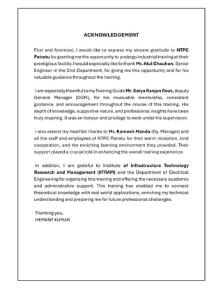
I completed a summer internship at Patratu Vidyut Utpadan Nigam Limited (PVUNL), a joint venture of NTPC Limited and Jharkhand Bijli Vitran Nigam Limited, located in Patratu, Jharkhand. PVUNL is developing modern, high-efficiency thermal power plants to meet growing energy needs.
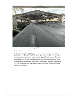
During my internship, I gained practical exposure to power plant operations, including coal handling systems, boiler and turbine functioning, water treatment, environmental management, and safety protocols. The training combined technical sessions and field visits, enhancing my understanding of large-scale electricity generation and plant maintenance practices.
I am grateful to the entire PVUNL team, especially Mr. Atul Chauhan (Senior Engineer, Civil Department), for their guidance and support.