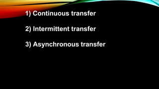
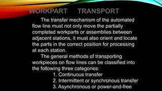
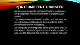
Modern Machine Tools:
CNC machines: Introduction, principles of operation,
Types – Vertical machining centres and horizontal machining centres,
major elements, functions, applications,
controllers,
open loop and closed loop systems
Types of automatic machines,
Transfer machines
Numerical Control (NC) machine tools – CNC types, constructional details, special features, machining centre, and part programming fundamentals CNC – manual part programming – micromachining – wafer machining
Numerical control (NC) machine tools - CNC: types, constructional details, special features - design considerations of CNC machines for improving machining accuracy -structural members - slide ways - linear bearings - ball screws - spindle drives and feed drives.
CNC Programming for Begainer.
1.Easy Mehtod.
2.Complete Theoritical Knowledge.
3.Motion and coordinate system for NC machine.
4.Axes convention of VMC & HMC.
5.How to make Part Programming.
6.Coordinates System.
7.Programming Format.
8.List of G Codes And M Codes.
9.How to Use of Above Codes In Programme.
10.Reference Point and Return of Machine.
This presentation is for academic purpose
Topics:-
1) Metal forming
2) Stress- strain analysis for forming process
3) Hot working and cold working process
4) Rolling process
5) Rolling mill arrangements
6) Rolling defects
7) Ring rolling
8) Thread rolling
9)Seamless Pipe Manufacturing By Rolling Process
10) Production of Steel Balls by Rolling Process
11) Roll-Forging
This presentation is for academic purpose
Topics:-
1) Polymer
2) Thermosetting plastic
3) Thermoplastic plastic
4) Moulding of Thermosetting plastic: Compression and transfer moulding
5) Moulding of Thermoplastic plastic
This presentation is for academic purpose
Topics:-
1) Steps in casting
2) Types of pattern
3) Materials used for pattern making
4) Pattern allowances
5)Sand
6) Core and types of core
7) Gating system
8) Chvorinov's rule
9) Freezing ratio
10) Special casting processes
11) Types of furnace
12) Casting Defects
NUMERICAL SIMULATIONS OF HEAT AND MASS TRANSFER IN CONDENSING HEAT EXCHANGERS...ssuser7dcef0
Power plants release a large amount of water vapor into the
atmosphere through the stack. The flue gas can be a potential
source for obtaining much needed cooling water for a power
plant. If a power plant could recover and reuse a portion of this
moisture, it could reduce its total cooling water intake
requirement. One of the most practical way to recover water
from flue gas is to use a condensing heat exchanger. The power
plant could also recover latent heat due to condensation as well
as sensible heat due to lowering the flue gas exit temperature.
Additionally, harmful acids released from the stack can be
reduced in a condensing heat exchanger by acid condensation. reduced in a condensing heat exchanger by acid condensation.
Condensation of vapors in flue gas is a complicated
phenomenon since heat and mass transfer of water vapor and
various acids simultaneously occur in the presence of noncondensable
gases such as nitrogen and oxygen. Design of a
condenser depends on the knowledge and understanding of the
heat and mass transfer processes. A computer program for
numerical simulations of water (H2O) and sulfuric acid (H2SO4)
condensation in a flue gas condensing heat exchanger was
developed using MATLAB. Governing equations based on
mass and energy balances for the system were derived to
predict variables such as flue gas exit temperature, cooling
water outlet temperature, mole fraction and condensation rates
of water and sulfuric acid vapors. The equations were solved
using an iterative solution technique with calculations of heat
and mass transfer coefficients and physical properties.
CW RADAR, FMCW RADAR, FMCW ALTIMETER, AND THEIR PARAMETERSveerababupersonal22
It consists of cw radar and fmcw radar ,range measurement,if amplifier and fmcw altimeterThe CW radar operates using continuous wave transmission, while the FMCW radar employs frequency-modulated continuous wave technology. Range measurement is a crucial aspect of radar systems, providing information about the distance to a target. The IF amplifier plays a key role in signal processing, amplifying intermediate frequency signals for further analysis. The FMCW altimeter utilizes frequency-modulated continuous wave technology to accurately measure altitude above a reference point.
6th International Conference on Machine Learning & Applications (CMLA 2024)ClaraZara1
6th International Conference on Machine Learning & Applications (CMLA 2024) will provide an excellent international forum for sharing knowledge and results in theory, methodology and applications of on Machine Learning & Applications.
Final project report on grocery store management system..pdfKamal Acharya
In today’s fast-changing business environment, it’s extremely important to be able to respond to client needs in the most effective and timely manner. If your customers wish to see your business online and have instant access to your products or services.
Online Grocery Store is an e-commerce website, which retails various grocery products. This project allows viewing various products available enables registered users to purchase desired products instantly using Paytm, UPI payment processor (Instant Pay) and also can place order by using Cash on Delivery (Pay Later) option. This project provides an easy access to Administrators and Managers to view orders placed using Pay Later and Instant Pay options.
In order to develop an e-commerce website, a number of Technologies must be studied and understood. These include multi-tiered architecture, server and client-side scripting techniques, implementation technologies, programming language (such as PHP, HTML, CSS, JavaScript) and MySQL relational databases. This is a project with the objective to develop a basic website where a consumer is provided with a shopping cart website and also to know about the technologies used to develop such a website.
This document will discuss each of the underlying technologies to create and implement an e- commerce website.
Immunizing Image Classifiers Against Localized Adversary Attacksgerogepatton
This paper addresses the vulnerability of deep learning models, particularly convolutional neural networks
(CNN)s, to adversarial attacks and presents a proactive training technique designed to counter them. We
introduce a novel volumization algorithm, which transforms 2D images into 3D volumetric representations.
When combined with 3D convolution and deep curriculum learning optimization (CLO), itsignificantly improves
the immunity of models against localized universal attacks by up to 40%. We evaluate our proposed approach
using contemporary CNN architectures and the modified Canadian Institute for Advanced Research (CIFAR-10
and CIFAR-100) and ImageNet Large Scale Visual Recognition Challenge (ILSVRC12) datasets, showcasing
accuracy improvements over previous techniques. The results indicate that the combination of the volumetric
input and curriculum learning holds significant promise for mitigating adversarial attacks without necessitating
adversary training.
Cosmetic shop management system project report.pdfKamal Acharya
Buying new cosmetic products is difficult. It can even be scary for those who have sensitive skin and are prone to skin trouble. The information needed to alleviate this problem is on the back of each product, but it's thought to interpret those ingredient lists unless you have a background in chemistry.
Instead of buying and hoping for the best, we can use data science to help us predict which products may be good fits for us. It includes various function programs to do the above mentioned tasks.
Data file handling has been effectively used in the program.
The automated cosmetic shop management system should deal with the automation of general workflow and administration process of the shop. The main processes of the system focus on customer's request where the system is able to search the most appropriate products and deliver it to the customers. It should help the employees to quickly identify the list of cosmetic product that have reached the minimum quantity and also keep a track of expired date for each cosmetic product. It should help the employees to find the rack number in which the product is placed.It is also Faster and more efficient way.
Hierarchical Digital Twin of a Naval Power SystemKerry Sado
A hierarchical digital twin of a Naval DC power system has been developed and experimentally verified. Similar to other state-of-the-art digital twins, this technology creates a digital replica of the physical system executed in real-time or faster, which can modify hardware controls. However, its advantage stems from distributing computational efforts by utilizing a hierarchical structure composed of lower-level digital twin blocks and a higher-level system digital twin. Each digital twin block is associated with a physical subsystem of the hardware and communicates with a singular system digital twin, which creates a system-level response. By extracting information from each level of the hierarchy, power system controls of the hardware were reconfigured autonomously. This hierarchical digital twin development offers several advantages over other digital twins, particularly in the field of naval power systems. The hierarchical structure allows for greater computational efficiency and scalability while the ability to autonomously reconfigure hardware controls offers increased flexibility and responsiveness. The hierarchical decomposition and models utilized were well aligned with the physical twin, as indicated by the maximum deviations between the developed digital twin hierarchy and the hardware.
2. NUMERICAL CONTROL (NC)
NC (numerical control) machine tools are the machine tool,
of which the various functions are controlled by : letters ,
numbers and symbols.
The NC machine tool runs on a program fed to it; without
human operator. The NC program consist of a set of instruction
or statement for controlling the motion of the drives of the
machine tools as well as the motion of the cutting tool.
3.
4. NC machine tools , one or more of the following function may
be automatic :
i. Starting and stopping of the machine tool spindle;
ii. Controlling the spindle speed;
iii. Positioning the tool at the desired location and guiding it along
the desired path by automatic control of the motion of slides;
iv. Controlling the feed rate; and
v. Changing the tools.
5.
6. COMPONENTS OF NC MACHINE TOOL SYSTEM
1. Part program:-
• Using the part drawing and the cutting parameters, the part
program is written.
• The part program is a set of step by instruction to the machine
tool for carrying out the operation.
• Method use for part programming
1. Manual part programming
2. Computer-aided part programming
7. 2. Program Tape:-
• The part program is entered on the program tape.
• The program is entered on the tape in the form of punched
holes. The holes are punched with the help of punching machine.
8. 3. Machine Control
Unit(MCU):-
• The program tape is read
by the tape reader.
• The controller takes input
from the tape reader.
4. Machine Tool:-
• The machine tool
is operated by
the controller of the
machine control unit.
9. NC COORDINATE
SYSTEMS
For flat and prismatic (block-like) parts:
Milling and drilling operations
Conventional Cartesian coordinate system
Rotational axes about each linear axis
11. MOTION CONTROL
SYSTEMS
• 1. Point-to-Point systems
• Also called position systems
• System moves to a location and performs an operation at that location (e.g., drilling)
• Also applicable in robotics
12. MOTION CONTROL SYSTEMS
2. Continuous path systems
• Also called contouring systems in machining
• System performs an operation during movement (e.g., milling
and turning)
14. ADVANTAGES OF NC MACHINE TOOL
• Cycle time reduction
• Complex machining operation
• High degree of accuracy
• Less inspection required
• Reduction of scrap and wastage
• Increasing productivity
• Lower tooling cost
• Reduction of human error
• Greater operation safety
• Greater operation efficiency
• Reduction space required
• Operator skill-level reduced
15. LIMITATION OF NC MACHINE TOOL
• High investment cost
• High maintenance effort
• Need for skilled programmers
• High utilization required
16. INTRODUCTION TO CNC MACHINE TOOLS
• In CNC (Computer Numerical Control) machines, a dedicated computer is used to
perform the most of basic NC machine functions.
• CNC (Computer Numerical Control) machine is a NC machine which uses a dedicated
computer as the machine control unit.
• The entire program is entered and stored in computer memory. The machining cyclefor
each component is controlled by the program contained in the computermemory.
• The stored part program listing can be used for future productionalso.
17. COMPONENTS OF CNC MACHINE TOOL SYSTEM
• The main components of CNC machine tools are as follows :
1. Input / Output Console.
2. Microprocessor Based control unit.
3. Memory.
4. Feedback unit.
5. Machine Tool.
6. Interfaces.
18. INPUT / OUTPUT
DEVICES
Machine Tool
Memory (ROM)
Control program for :
Z Slide
X Slide
Memory (RAM)
Part Program
Feed Back Unit
19. • Input / Output Console : It is the unit through which part program is fed to the CNC
machine tool system and required output is taken out. It basically consists of monitor and
Keyboard.
• Microprocessor : This controller takes input from Input / Output device, Feedback from
feedback unit and actuates the drives as well as the tool of the machine tool.
• Memory : It consists of RAM & ROM. The RAM stores part program, while ROM stores
the programs for machine control.
• Feedback unit : The feedback unit takes input from machine tool and transfers it to control
unit for necessary corrections.
• Machine tool : Machine tool is operated by the control unit.
• Interfaces : They are the connections between the different components of the CNC
machine tool system.
20.
21. CLASSIFICATION OF CNC MACHINE
TOOL SYSTEMS
• (d) According to type of controller
1. Hybrid controller CNC systems.
2. Straight controller CNC systems.
• (e) According to axis & type of
operations
1. CNC horizontal machining centre.
2. CNC vertical machining centre.
3. CNC turning centre.
4. CNC milling centre.
(a) According to type of Feedbacksystems
1. Open loop type CNC machine.
2. Closed loop type CNC machine.
(b) According to type of tool motioncontrol
1. Finite positioning control CNC machines.
2. Continuous path control CNC machines.
(c) According to programmethods
1. Absolute Programming CNC machine systems.
2. Incremental Programming CNC machine systems.
22. CLASSIFICATION BASED ON TYPE OF FEEDBACK SYSTEMS
Input Program Microcomputer
CNC controllerDrive motor
Gear box
Machine tool
slide
displacement
• It does not have any feedback
mechanism.
• It only has motion control but do not
have any provision for feedback, which
is needed to be compared with input for
better control & correction of drive
system.
23. CLASSIFICATION BASED ON TYPE OF FEEDBACK SYSTEMS
Input Program
Microcomputer
CNC controller
Drive motorGear box
Machine tool
slide
displacement
Measuring unit
• It has a feedback mechanism.
• It has the motion control with a provision
of feedback of feedback.
• Which can be used for accurately
controlling the drive system by
comparing it with the input information
until the required or desired position is
achived.
24. ACCORDING TO TYPE OF TOOL MOTION
CONTROL:
• In poin
t
to point CNC machines, the
movement of cutting tool from one
predefined position to another predefined
position is important, while the path along
which this tool moves is irrelevant.
Commonly used in drilling & punching
operations.
• Straight cut line control mode is the
extension version of point to point method,
straight cut is obtained controlling the
movement of tool with controlled feed rate
in one of the axis direction at a time.
Commonly used in Face milling, pocket
milling and step turning operations.
25. ACCORDING TO TYPE OF TOOL MOTION CONTROL:
• The continuous path control system is
used for continuous, simultaneous &
coordinated motions of cutting tool &
work piece along different axes.
• Such motion enables machining of
different contoured profiles & curved
surfaces.
• Types : 2 axis, 2 ½ axis, 3 axis, Multi
axis countering.
26.
27. ACCORDING TO PROGRAMMING METHODS
• In Cartesian coordinate geometry
system using absolute measurement,
each point is always specified using
same zero established for a given
coordinate system.
X Y
0 0
0 4
2 4
2 5
4 6
4 7
6 6
8 8
8 4
5 4
28. ACCORDING TO PROGRAMMING METHODS
• In Cartesian coordinate geometry
system using incremental measurement
, each point is specified using the path
differential from the preceding point
position. So in such programming ,
controller must store and process
additional path measurement.
X Y
0 0
0 4
2 0
0 1
2 1
0 1
2 -1
2 2
0 -4
- -
29. ACCORDING TO TYPE OF
CONTROLLERS
1. Hard wired logic circuits : It performs
those functions for which they are best
suited, such as feed rate generation
and interpolation.
2. Soft wired computer : The computer
normally associated with
performs the remaining control
functions plus other duties not
a
conventional hard-wired controller.
Minicomputer Hard-Wired logic
Circuits
Interface
Feedback
30. ACCORDING TO TYPE OF CONTROLLERS
• It uses a computer to perform all the
functions.
• The interpolation, feed rate generation
and all other functions are performed by
the computer with the help of software.
• The only hard-wired elements are those
required to interface the computer with
machine tool and operator’s console.
Minicomputer
Interface
Feedback
31. ADVANTAGES & LIMITATIONS OF CNC MACHINE TOOLS
• Advantages
• Ease of program input.
• Multiple program storage.
• Online part programming and editing.
• Use of advanced interpolation.
• Automatic tool compensation.
• Auto generation of part program for
• existing components.
• Change in system of units.
Limitations
• Higher investment cost.
• Higher maintenance cost.
• Requires specialised operators.
32. INTRODUCTION DNC
• DNC is a manufacturing system in which a number of machines are controlled by a computer
through direct- connection and in real time.
• Also, defined by EIA as: DNC is a system connecting a set of NC machines to a common memory
for part program or machine program storage with provision for on- demand distribution of data to
machines.
• The tape reader is omitted.
• Involves data connection and processing from the machine tool back to thecomputer.
35. • A central computer connected to a number of machine tools and controlthem
• Part program of all machine tools are stored in the memory of the central computer and transmitted on
direct transmission lines on demand
• Two way information flow take place in real time
• Various machine tools can communicate with the computer in real time
• Programs in full or segment can be transferred to NC machines
• Computer can be used for program editing
• No tape readers are used
• No limitation for the number or size of programs stored
36. The configuration of the DNC system can be divided into:
1. DNC system without satellite computer.
2. DNC system with satellite computer.
Satellite computers are minicomputers and they serve to take some of the burden off central
computer. Each satellites controls several machine tools.
39. FUNCTIONS OF DNC
The functions which a DNC system is designed to perform:
1. NC without punched tape.
2. NC part program storage.
3. Data collection, processing, and reporting.
4. Communication
40. ADVANTAGES OF DNC SYSTEM
• Elimination of punched tapes and tape readers
• Convenient storage of NC part programs in computer files
• Greater computational capability and flexibility
• Reporting of shop performance.
• Convenient editing and diagnostic features.
41. COMPARISON BETWEEN NC, CNC AND DNC MACHINE TOOLS
1. The part program is fed to the machine
through the tapes or other such
media.
2. In order to modify the program, the
tapes have to be changed.
3. In NC machine tool system, tape reader
is a part of machine control unit.
4. System has no memory storage and
each time it is run using the tape.
5. It can not import CAD files.
6. It can not use feedback system.
7. They are not software driven.
1. In CNC machine tool system, the
program is fed to the machine through
the computer.
2. The programs can be easily modified
with the help of computer.
3. The microprocessor or minicomputer
forms the machine control unit. The
CNC machine does not need tape
reader.
4. It has memory storage ability, in which
part program can be stored.
5. System can import CAD files and
convert it to part program.
6. The system can use feedback system.
7. The system is software driven.
1. The part program is fed to the
machine through the Main computer
2. In order to modify the program,
single computer is used
3. Large memory of DNC allows it to
store a large amount of part
program.
4. Same part program can be run on
different machines at the same time.
5. The data can be processed using the
MIS software so as to effectively
carry out the Production planning
and scheduling.
42.
43. FUNDAMENTS
An automated Transfer line consists of several machines or
workstations which are linked together by work handling devices that
transfer parts between the stations.
The transfer of work parts occurs automatically and the workstations
carry out their specialized functions automatically.
45. Objectives of the use of Transfer line
To reduce labor costs
To increase production rates
To reduce work-in-process
To minimize distances moved between
operations
To achieve specialization of operations
To achieve integration of operations
47. INLINE TYPE
The in-line configuration consists of a sequence
of workstations in a more-or-less straight-line
arrangement as shown in figure 1. An example of
an in-line transfer machine used for metal-cutting
operations is illustrated in Figure
48. SEGMENTED IN-LINE TYPE
The segmented in-line configuration consists of
two or more straight-line arrangement which are
usually perpendicular to each other with L-
Shaped or U-shaped or
The flow of work can take a few 90°turns, either
for workpieces reorientation,
factory layout limitations, qualify as a straight-
line configuration.
or other reasons, and still
52. ROTARY TYPE
In the rotary configuration, the workparts are indexed
around a circular table or dial.
The workstations are stationary and usually located
around the outside periphery of the dial.
The parts ride on the rotating table and arc registered or
positioned, in turn, at each station for its processing or
assembly operation.
This type of equipment is often referred
to as an indexing machine or dial index
Machine and the configuration
54. WORKPART TRANSPORT
The transfer mechanism of the automated
flow line must not only move the partially
completed workparts or assemblies between
adjacent stations, it must also orient and locate
the parts in the correct position for processing
at each station.
The general methods of transporting
workpieces on flow lines can be classified into
the following three categories:
1. Continuous transfer
2. Intermittent or synchronous transfer
3. Asynchronous or power-and-free
55. ALSO…
The most appropriate type of transport system for a
given application depends on such factors as:
The types of operation to be performed
The number of stations on the line
The weight and size of the work parts
Whether manual stations are included on the line
Production rate requirements
Balancing the various process times on the line
56. 1) CONTINUOUS TRANSFER
The workparts are moved continuously at Constant
speed.
This requires the workheads to move during
processing in order to maintain continuous registration
with the workpart.
For some types of operations, this movement of the
workheads during processing is not feasible, It would
be difficult for example, to use this type of system on a
machining transfer line because of inertia problems
due to the size and weight of the workheads.
Examples of its use are
In beverage bottling operations,
Packaging,
57. 2) INTERMITTENT TRANSFER
As the name suggests, in this method the workpieces
are transported with an intermittent or discontinuous
motion.
The workstations are fixed in position and the parts are
moved between stations and then registered at the
proper locations for processing.
All workparts are transported at the same time and, for
this reason, the term "synchronous transfer system" is
also used to describe this method of workpart transport
.
58. 3) ASYNCHRONOUS TRANSFER
This system of transfer, also referred to as a "power-and-free
system,“
It allows each workpart to move to the next station when
processing at the current station has been completed.
Each part moves independently of other parts. Hence, some
parts are being processed on the line at the same time that
others are being transported between stations.
Asynchronous transfer systems offer the opportunity for
greater flexibility than do the other two systems, and this
flexibility can be a great advantage in certain circumstances.
In-process storage of workparts can be incorporated into the
asynchronous systems with relative ease.
Parallel stations or several series stations can be used for the
longer operations
Single stations can be used for the shorter operations.
A disadvantage of the power and-free systems is that the cycle
59. TRANSFER MECHANISMS-
There are various types of transfer mechanisms
used to move parts between stations.
These mechanisms can be grouped into two
types: # Linear travel for in-
line machines, # Rotary motion
for dial indexing machines.
60. LINEAR TRANSFER SYSTEM
We will explain the operation of three of the typical
mechanisms; The walking beam transfer bar
system
The powered roller conveyor system, and
The chain-drive conveyor system.
61. THE WALKING BEAM
TRANSFER BAR SYSTEM
The work-parts are lifted up from their workstation locations by a transfer bar
and moved one position ahead, to the next station.
The transfer bar then lowers the pans into nests which position them more accu
for processing.
For speed and accuracy, the motion of the beam is most often generated by a
rotating camshaft powered by an electric motor or a roller movement in a prof
owered by hydraulic cylinder
62.
63. CHAIN-DRIVE CONVEYOR
SYSTEM
Either a chain or a flexible steel belt is used to transport
the work carriers.
The chain is driven by pulleys in either an “over-and-
under“ config, in which the pulleys turn about a horizontal
axis, or an “around-the-corner“ configuration, in which
the pulleys rotate about a vertical axis.
64. Rotary transfer mechanisms
There are several methods used to index a
circular table or dial at various equal angular
positions corresponding to workstation locations.
65. CONTROL FUNCTIONS
Controlling an automated flow line is a complex problem,
owing to the sheer number of sequential steps that must
be carried out. There are three main functions that are
utilized to control the operation of an automatic transfer
system.
The first of there is an operational requirement, the
second is a safety requirement, and the third is dedicated
to improving quality.
Sequence control.
Safety monitoring
Quality monitoring
Instantaneous control
Memory control
66. Sequence control.
The purpose of this function is to coordinate the
sequence of actions of the transfer system and its
workstations. The various activities of the automated flow
line must be carried out with split-second timing and
accuracy. Sequence control is basic to the operation of
the flow line
Safety monitoring:
This function ensures that the transfer system does not
operate in an unsafe or hazardous condition. Sensing
devices may be added to make certain that the cutting
tool status is satisfactory to continue to process the
workpart in the case of a machining-type transfer line.
Other checks might include monitoring certain critical
steps in the sequence control function to make sure that
these steps have all been performed and in the correct
67. Quality monitoring:
The third control function is to monitor certain quality attributes of the
workpart. Its purpose is to identify and possibly reject defective workparts
and assemblies. The inspection devices required to perform quality
monitoring are sometimes incorporated into existing processing stations.
68. Conventional thinking on the control of the line has been
to stop operation when a malfunction occurred. While
there are certain malfunctions representing unsafe
conditions that demand shutdown of the line, there are
other situations where stoppage of the line is not
required and perhaps not even desirable. There are
alternative control strategies
1.Instantaneous control and
2. Memory control.
69. Instantaneous control:
This mode of control stops the operation of the flow line immediately
when a malfunction is detected. It is relatively simple, inexpensive,
and trouble-free. Diagnostic features are often added to the system to
aid in identifying the location and cause of the trouble to the operator
so that repairs can be quickly made. However, stopping the machine
results in loss of production from the entire line, and this is the
system's biggest drawback.
Memory control:
In contrast to instantaneous control, the memory system is designed
to keep the machine operating. It works to control quality and/or
protect the machine by preventing subsequent stations from
processing the particular workpart and by segregating the part as
defective at the end of the line. The premise upon which memory-type
control is based is that the failures which occur at the stations will be
random and infrequent. If, however, the station failures result from
cause and tend to repeat, the memory system will not improve
production but, rather, degrade it. The flow line will continue to
operate, with the consequence that bad parts will continue to be
produced. For this reason, a counter is sometimes used so
70. BUFFER STORAGE
It is not uncommon for production flow lines to include storage zones for
collecting banks of workparts along the line.
One example of the use of storage zones would be two intermittent
transfer systems, each without any storage capacity, linked together with
a workpart inventory area.
It is possible to connect three, four, or even more lines in this manner.
Another example of workpart storage on flow lines is the asynchronous
transfer line.
With this system, it is possible to provide a bank of workparts for every
station on the line.