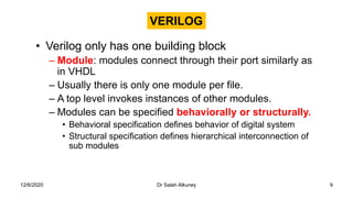
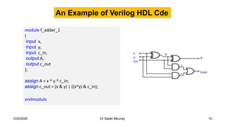
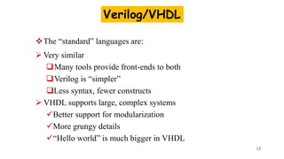
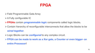
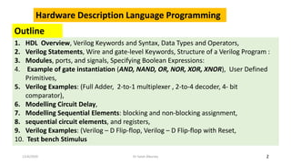
Hardware Description Language (HDL )
Programming
12/6/2020 Dr Salah Alkurwy 1
2
1. HDL Overview, Verilog Keywords and Syntax, Data Types and Operators,
2. Verilog Statements, Wire and gate-level Keywords, Structure of a Verilog Program :
3. Modules, ports, and signals, Specifying Boolean Expressions:
4. Example of gate instantiation (AND, NAND, OR, NOR, XOR, XNOR), User Defined
Primitives,
5. Verilog Examples: (Full Adder, 2-to-1 multiplexer , 2-to-4 decoder, 4- bit
comparator),
6. Modelling Circuit Delay,
7. Modelling Sequential Elements: blocking and non-blocking assignment,
8. sequential circuit elements, and registers,
9. Verilog Examples: (Verilog – D Flip-flop, Verilog – D Flip-flop with Reset,
10. Test bench Stimulus
Hardware Description Language Programming
12/6/2020 Dr Salah Alkurwy
Outline
¿VHDL & Verilog?
 Hardware description language (HDL) is a specialized computer
language used to describe the structure and behavior of electronic
circuits, and most commonly, digital logic circuits.
 There are two most common Hardware Description Languages (HDL)
used by integrated circuit (IC) designers.
 Verilog HDL
 VHDL.
 They are each a notation to describe the behavioral and structural
aspects of an electronic digital circuit.
3
12/6/2020 Dr Salah Alkurwy
VHDL Background
 VHSIC Hardware Description Language.
VHSIC is an abbreviation for Very High Speed Integrated Circuit.
 Developed by the department of defense (1981)
 In 1986 rights where given to IEEE
• Became a standard and published in 1987
• Revised standard we know now published in 1993 (VHDL 1076-1993)
regulated by VHDL international (VI)
4
12/6/2020 Dr Salah Alkurwy
VHDL
 Uses top-down approach to partition design into small blocks
‘components’
 Entity: describes interface signals & basic building blocks
 Architecture: describes behavior, each entity can have
multiple Architectures
 Configuration: sort of parts list for a design, which behavior
to use for each entity.
 Package: toolbox used to build design
5
12/6/2020 Dr Salah Alkurwy
6
12/6/2020 Dr Salah Alkurwy
• VHDL represents another high level language for digital
system design.
• In this course we study Verilog HDL
– reason:
• used more often in electronic and computer industry
• programming style is very similar to C programming
language
7
Verilog Background
 Developed by Gateway Design Automation (1980)
 Later acquired by Cadence Design(1989) who made
it public in 1990
 Became a standardized in 1995 by IEEE (Std 1364)
regulated by Open Verilog International (OVI)
8
Gateway Design Automation. The company was privately held at that time by Dr. Prabhu
Goel, the inventor of the PO in 1985 DEM (Path-Oriented Decision Making) test generation
algorithm.[1] Verilog HDL was designed by Phil Moorby who was later to become the Chief
Designer for Verilog-XL
12/6/2020 Dr Salah Alkurwy
• Verilog only has one building block
– Module: modules connect through their port similarly as
in VHDL
– Usually there is only one module per file.
– A top level invokes instances of other modules.
– Modules can be specified behaviorally or structurally.
• Behavioral specification defines behavior of digital system
• Structural specification defines hierarchical interconnection of
sub modules
VERILOG
9
12/6/2020 Dr Salah Alkurwy
12/6/2020 Dr Salah Alkurwy 10
module f_adder_1
(
input x,
input y,
input c_in,
output A,
output c_out
);
assign A = x ^ y ^ c_in;
assign c_out = (x & y) | ((x^y) & c_in);
endmodule
An Example of Verilog HDL Cde
• Verilog Hardware Description Language(HDL)
– A high-level computer language can model, represent and simulate digital
design
• Hardware concurrency
• Parallel Activity Flow
• Semantics for Signal Value and Time
– Design examples using Verilog HDL
• Intel Pentium, AMD K5, K6, Atheon, ARM7, etc
• Thousands of ASIC designs using Verilog HDL
What is Verilog HDL?
11
The “standard” languages are:
 Very similar
Many tools provide front-ends to both
Verilog is “simpler”
Less syntax, fewer constructs
 VHDL supports large, complex systems
Better support for modularization
More grungy details
“Hello world” is much bigger in VHDL
Verilog/VHDL
12
• These languages have taken designers from low level detail to
much higher level of abstraction.
• In 2000 VI & OVI merged into Accellera
• Simulation & synthesis are the two main kinds of tools which
operate on the VHDL & Verilog languages.
• They are not a toolset or methodology they are each a different
language.
– However toolsets and methodologies are essential for their effective use.
Similarities
13
12/6/2020 Dr Salah Alkurwy
• There are not many differences as to the capabilities of
each.
• The choice of which one to use is often based in personal
preference & other issues such as availability of tools &
commercial terms.
• VHDL is “harder” to learn ADA-like.
• Verilog is “easier” to learn C-like.
Differences?
14
12/6/2020 Dr Salah Alkurwy
Field Programmable Gate Array
A Fully configurable IC
FPGAs contain programmable logic components called logic blocks.
Contain hierarchy of reconfigurable interconnects that allow the blocks to be
wired together.
Logic Blocks can be configured to any complex circuit.
FPGA can be made to work as a Xor gate, a Counter or even bigger- an
entire Processor!
FPGA
15
Advancements over the years
 © Intel 4004
Processor
 Introduced in 1971
 2300 Transistors
 108 KHz Clock
 © Intel P4 Processor
 Introduced in 2000
 40 Million Transistors
 1.5GHz Clock 16
17
FPGA Kit Board
18
ALTERA Quartus II
12/6/2020 Dr Salah Alkurwy 19
xilinx ISE
20

Verilog HDL 0001.pdf

  • 1.
    Hardware Description Language(HDL ) Programming 12/6/2020 Dr Salah Alkurwy 1
  • 2.
    2 1. HDL Overview,Verilog Keywords and Syntax, Data Types and Operators, 2. Verilog Statements, Wire and gate-level Keywords, Structure of a Verilog Program : 3. Modules, ports, and signals, Specifying Boolean Expressions: 4. Example of gate instantiation (AND, NAND, OR, NOR, XOR, XNOR), User Defined Primitives, 5. Verilog Examples: (Full Adder, 2-to-1 multiplexer , 2-to-4 decoder, 4- bit comparator), 6. Modelling Circuit Delay, 7. Modelling Sequential Elements: blocking and non-blocking assignment, 8. sequential circuit elements, and registers, 9. Verilog Examples: (Verilog – D Flip-flop, Verilog – D Flip-flop with Reset, 10. Test bench Stimulus Hardware Description Language Programming 12/6/2020 Dr Salah Alkurwy Outline
  • 3.
    ¿VHDL & Verilog? Hardware description language (HDL) is a specialized computer language used to describe the structure and behavior of electronic circuits, and most commonly, digital logic circuits.  There are two most common Hardware Description Languages (HDL) used by integrated circuit (IC) designers.  Verilog HDL  VHDL.  They are each a notation to describe the behavioral and structural aspects of an electronic digital circuit. 3 12/6/2020 Dr Salah Alkurwy
  • 4.
    VHDL Background  VHSICHardware Description Language. VHSIC is an abbreviation for Very High Speed Integrated Circuit.  Developed by the department of defense (1981)  In 1986 rights where given to IEEE • Became a standard and published in 1987 • Revised standard we know now published in 1993 (VHDL 1076-1993) regulated by VHDL international (VI) 4 12/6/2020 Dr Salah Alkurwy
  • 5.
    VHDL  Uses top-downapproach to partition design into small blocks ‘components’  Entity: describes interface signals & basic building blocks  Architecture: describes behavior, each entity can have multiple Architectures  Configuration: sort of parts list for a design, which behavior to use for each entity.  Package: toolbox used to build design 5 12/6/2020 Dr Salah Alkurwy
  • 6.
  • 7.
    • VHDL representsanother high level language for digital system design. • In this course we study Verilog HDL – reason: • used more often in electronic and computer industry • programming style is very similar to C programming language 7
  • 8.
    Verilog Background  Developedby Gateway Design Automation (1980)  Later acquired by Cadence Design(1989) who made it public in 1990  Became a standardized in 1995 by IEEE (Std 1364) regulated by Open Verilog International (OVI) 8 Gateway Design Automation. The company was privately held at that time by Dr. Prabhu Goel, the inventor of the PO in 1985 DEM (Path-Oriented Decision Making) test generation algorithm.[1] Verilog HDL was designed by Phil Moorby who was later to become the Chief Designer for Verilog-XL 12/6/2020 Dr Salah Alkurwy
  • 9.
    • Verilog onlyhas one building block – Module: modules connect through their port similarly as in VHDL – Usually there is only one module per file. – A top level invokes instances of other modules. – Modules can be specified behaviorally or structurally. • Behavioral specification defines behavior of digital system • Structural specification defines hierarchical interconnection of sub modules VERILOG 9 12/6/2020 Dr Salah Alkurwy
  • 10.
    12/6/2020 Dr SalahAlkurwy 10 module f_adder_1 ( input x, input y, input c_in, output A, output c_out ); assign A = x ^ y ^ c_in; assign c_out = (x & y) | ((x^y) & c_in); endmodule An Example of Verilog HDL Cde
  • 11.
    • Verilog HardwareDescription Language(HDL) – A high-level computer language can model, represent and simulate digital design • Hardware concurrency • Parallel Activity Flow • Semantics for Signal Value and Time – Design examples using Verilog HDL • Intel Pentium, AMD K5, K6, Atheon, ARM7, etc • Thousands of ASIC designs using Verilog HDL What is Verilog HDL? 11
  • 12.
    The “standard” languagesare:  Very similar Many tools provide front-ends to both Verilog is “simpler” Less syntax, fewer constructs  VHDL supports large, complex systems Better support for modularization More grungy details “Hello world” is much bigger in VHDL Verilog/VHDL 12
  • 13.
    • These languageshave taken designers from low level detail to much higher level of abstraction. • In 2000 VI & OVI merged into Accellera • Simulation & synthesis are the two main kinds of tools which operate on the VHDL & Verilog languages. • They are not a toolset or methodology they are each a different language. – However toolsets and methodologies are essential for their effective use. Similarities 13 12/6/2020 Dr Salah Alkurwy
  • 14.
    • There arenot many differences as to the capabilities of each. • The choice of which one to use is often based in personal preference & other issues such as availability of tools & commercial terms. • VHDL is “harder” to learn ADA-like. • Verilog is “easier” to learn C-like. Differences? 14 12/6/2020 Dr Salah Alkurwy
  • 15.
    Field Programmable GateArray A Fully configurable IC FPGAs contain programmable logic components called logic blocks. Contain hierarchy of reconfigurable interconnects that allow the blocks to be wired together. Logic Blocks can be configured to any complex circuit. FPGA can be made to work as a Xor gate, a Counter or even bigger- an entire Processor! FPGA 15
  • 16.
    Advancements over theyears  © Intel 4004 Processor  Introduced in 1971  2300 Transistors  108 KHz Clock  © Intel P4 Processor  Introduced in 2000  40 Million Transistors  1.5GHz Clock 16
  • 17.
  • 18.
  • 19.
    12/6/2020 Dr SalahAlkurwy 19 xilinx ISE
  • 20.