Download as PPSX, PPTX
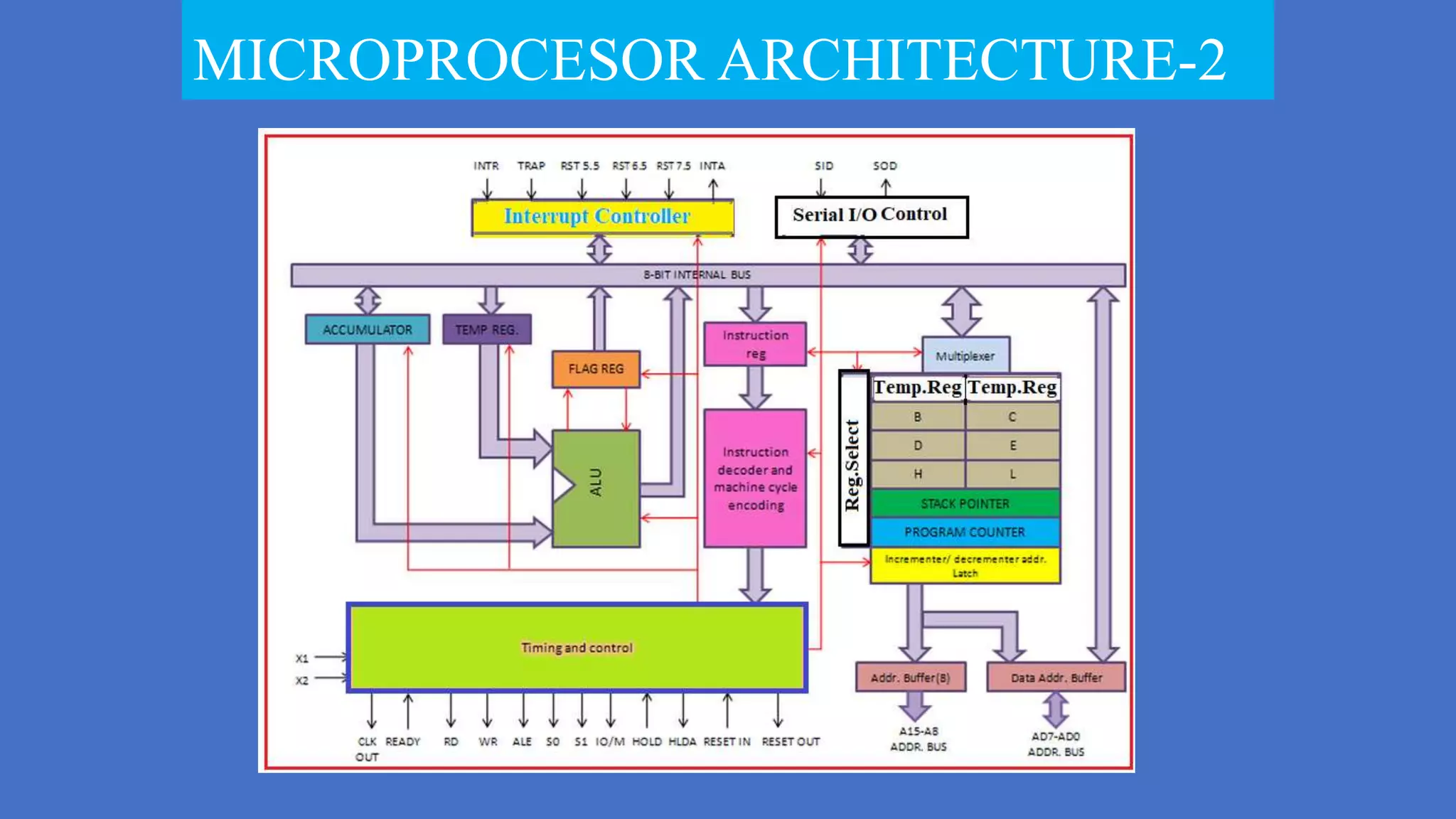
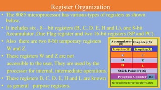

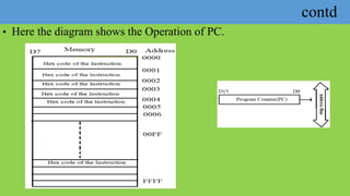
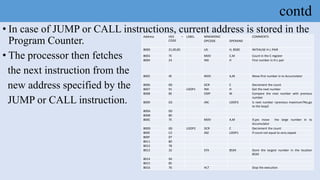
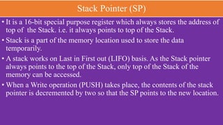
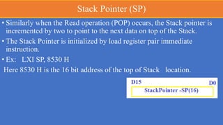
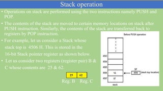
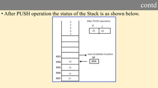
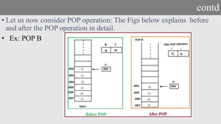


The document details the register organization of the 8085 microprocessor, which includes various types of registers: six 8-bit general-purpose registers (B, C, D, E, H, L), one 8-bit accumulator, one flag register, and two 16-bit special-purpose registers (stack pointer and program counter). It explains the function of the program counter and stack pointer in instruction execution and memory management, emphasizing their roles in addressing and temporary data storage. Additionally, it covers temporary registers (W and Z) which are used by the processor for internal operations and are not accessible to users.