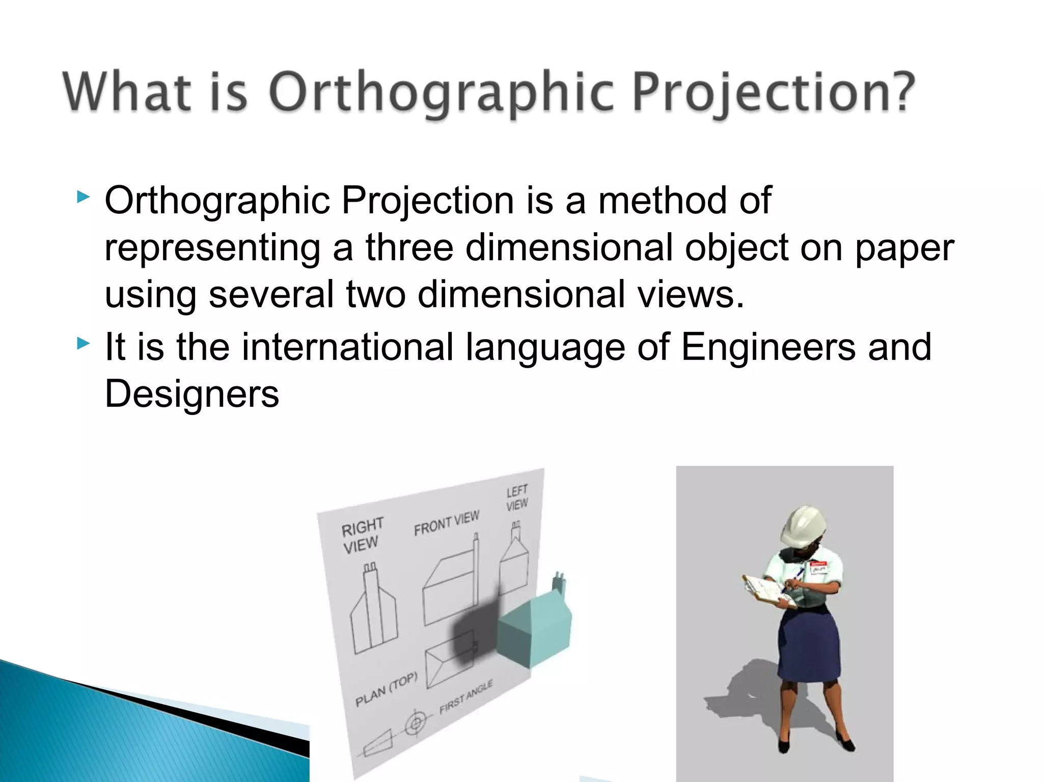
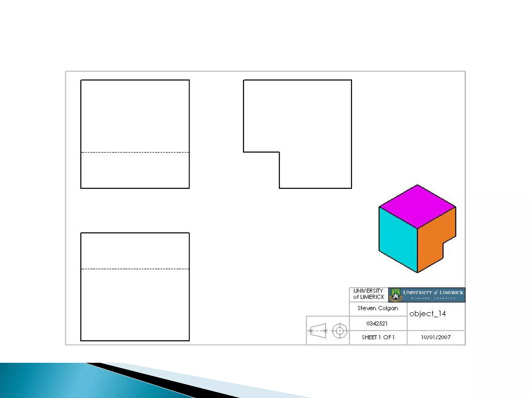
Name : Vaghani Milan
: Shubham Patel
En.No :140420129027
:140420129026
Branch:textiles technology
 Orthographic Projection is a method of
representing a three dimensional object on paper
using several two dimensional views.
 It is the international language of Engineers and
Designers
 We look directly at the different faces of the object
(90˚ to the face) and draw the lines that we see.
 One view is never enough to describe an object.
 We need at least two views to accurately describe
even the most simple of objects.
 Generally we se three views and arrange them as
shown in the movie
 You can use as many views as the object
requires.
 Yes. However America and Australia arrange the
views differently.
 This arrangement of views is called third angle
projection.
 Each method has its own symbol and they are as
follows
 First angle projection
 Third angle projection
 The recommended proportions for the symbol are
as follows
 The name first angle is derived from the objects
position in the first quadrant of the planes of
reference.
 The name third angle is derived from the objects
position in the third quadrant of the planes of
reference.
 Sometimes features of an object are hidden (for
example they are at the back of the object)
 To show these features we add dashed lines in
their place.
 If a dashed line meets a thick line leave a gap as
shown.
 If there is too much hidden detail and the drawing
becomes confusing use a sectional view.
 Draw the Hatching lines at 45˚ as shown
 Always place the section line (the dashed line that
ends in arrows) exactly were you are cutting the
object.
 Make sure you keep your drawing neat.
 Recommended proportions are shown below.
 Keep construction lines light and finished lines
heavy

Orthographic projection

  • 1.
    Name : VaghaniMilan : Shubham Patel En.No :140420129027 :140420129026 Branch:textiles technology
  • 2.
     Orthographic Projectionis a method of representing a three dimensional object on paper using several two dimensional views.  It is the international language of Engineers and Designers
  • 3.
     We lookdirectly at the different faces of the object (90˚ to the face) and draw the lines that we see.
  • 4.
     One viewis never enough to describe an object.  We need at least two views to accurately describe even the most simple of objects.  Generally we se three views and arrange them as shown in the movie  You can use as many views as the object requires.
  • 6.
     Yes. HoweverAmerica and Australia arrange the views differently.  This arrangement of views is called third angle projection.
  • 8.
     Each methodhas its own symbol and they are as follows  First angle projection  Third angle projection
  • 9.
     The recommendedproportions for the symbol are as follows
  • 10.
     The namefirst angle is derived from the objects position in the first quadrant of the planes of reference.  The name third angle is derived from the objects position in the third quadrant of the planes of reference.
  • 12.
     Sometimes featuresof an object are hidden (for example they are at the back of the object)  To show these features we add dashed lines in their place.  If a dashed line meets a thick line leave a gap as shown.
  • 14.
     If thereis too much hidden detail and the drawing becomes confusing use a sectional view.  Draw the Hatching lines at 45˚ as shown  Always place the section line (the dashed line that ends in arrows) exactly were you are cutting the object.
  • 16.
     Make sureyou keep your drawing neat.  Recommended proportions are shown below.  Keep construction lines light and finished lines heavy