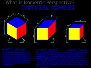
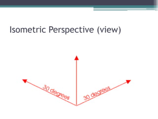
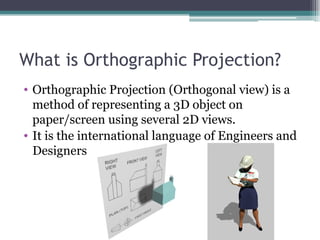
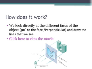
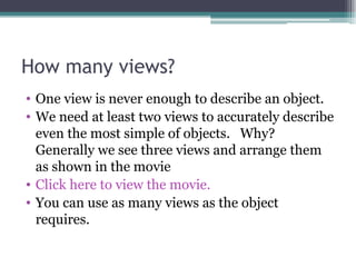
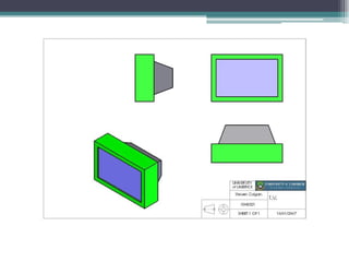
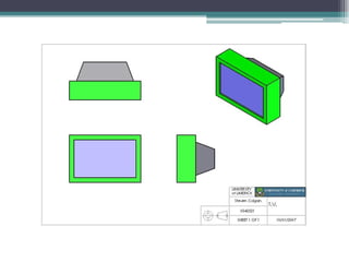
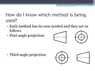
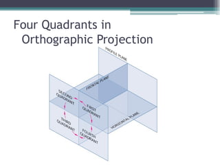
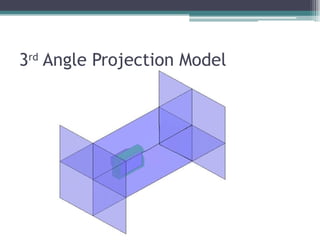
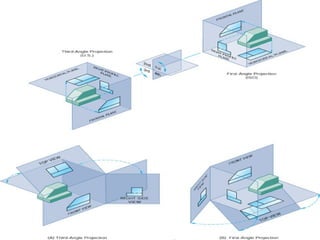
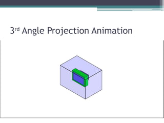
Isometric Perspective & Third Angle Orthographic Projection Modified modelling & presentation by Mr. Spencer, CQUniversity Australia, 2010 Materials & models by Steven Colburn, Limerick University Ireland.
What is Isometric Perspective?
Isometric Perspective (view)
What is Orthographic Projection? Orthographic Projection (Orthogonal view) is a method of representing a 3D object on paper/screen using several 2D views. It is the international language of Engineers and Designers
How does it work? We look directly at the different faces of the object (90 ˚ to the face /Perpendicular) and draw the lines that we see. Click here to view the movie
How many views? One view is never enough to describe an object. We need at least two views to accurately describe even the most simple of objects.  Why? Generally we see three views and arrange them as shown in the movie Click here to view the movie. You can use as many views as the object requires.
 
Is it really an international language? Yes. However America and Australia arrange the views differently. This arrangement of views is called third angle projection. Click here to view the movie
 
How do I know which method is being used? Each method has its own symbol and they are as follows First angle projection Third angle projection
Four Quadrants in  Orthographic Projection
3 rd  Angle Projection Model
How did they get their names? The name first angle is derived from the objects position in the first quadrant of the planes of reference. The name third angle is derived from the objects position in the third quadrant of the planes of reference.
3 rd  Angle Projection Animation
Is that it? Sometimes features of an object are hidden (for example they are at the back of the object) To show these features we add dashed lines in their place. Click here to view the movie If a dashed line meets a thick line leave a gap as shown Click here to view the movie
What next? Test Yourself:  http://www.ul.ie/~rynnet/orthographic_projection_fyp/webpages/home.html   Open AutoCAD Prior knowledge:  use of AutoCAD 2D/ 3D Introductory lessons (if required – Student Email or Folder) Open Template File (Master Template A3 2010) on shared drive? Draw Object 3D & save, save, save!!! Project Orthogonal views (3 rd  Angle Projection)
 
There’s too many dashed lines! If there is too much hidden detail and the drawing becomes confusing use a sectional view Click here to view the movie Draw the Hatching lines at 45 ˚ as shown Always place the section line (the dashed line that ends in arrows) exactly were you are cutting the object. To see more types of Sectional views  click here
 
Anything else? Make sure you keep your drawing neat.  Recommended proportions are shown below. Keep construction lines light and finished lines heavy

Orthographic projection

  • 1.
    Isometric Perspective &Third Angle Orthographic Projection Modified modelling & presentation by Mr. Spencer, CQUniversity Australia, 2010 Materials & models by Steven Colburn, Limerick University Ireland.
  • 2.
    What is IsometricPerspective?
  • 3.
  • 4.
    What is OrthographicProjection? Orthographic Projection (Orthogonal view) is a method of representing a 3D object on paper/screen using several 2D views. It is the international language of Engineers and Designers
  • 5.
    How does itwork? We look directly at the different faces of the object (90 ˚ to the face /Perpendicular) and draw the lines that we see. Click here to view the movie
  • 6.
    How many views?One view is never enough to describe an object. We need at least two views to accurately describe even the most simple of objects. Why? Generally we see three views and arrange them as shown in the movie Click here to view the movie. You can use as many views as the object requires.
  • 7.
  • 8.
    Is it reallyan international language? Yes. However America and Australia arrange the views differently. This arrangement of views is called third angle projection. Click here to view the movie
  • 9.
  • 10.
    How do Iknow which method is being used? Each method has its own symbol and they are as follows First angle projection Third angle projection
  • 11.
    Four Quadrants in Orthographic Projection
  • 12.
    3 rd Angle Projection Model
  • 13.
    How did theyget their names? The name first angle is derived from the objects position in the first quadrant of the planes of reference. The name third angle is derived from the objects position in the third quadrant of the planes of reference.
  • 14.
    3 rd Angle Projection Animation
  • 15.
    Is that it?Sometimes features of an object are hidden (for example they are at the back of the object) To show these features we add dashed lines in their place. Click here to view the movie If a dashed line meets a thick line leave a gap as shown Click here to view the movie
  • 16.
    What next? TestYourself: http://www.ul.ie/~rynnet/orthographic_projection_fyp/webpages/home.html Open AutoCAD Prior knowledge: use of AutoCAD 2D/ 3D Introductory lessons (if required – Student Email or Folder) Open Template File (Master Template A3 2010) on shared drive? Draw Object 3D & save, save, save!!! Project Orthogonal views (3 rd Angle Projection)
  • 17.
  • 18.
    There’s too manydashed lines! If there is too much hidden detail and the drawing becomes confusing use a sectional view Click here to view the movie Draw the Hatching lines at 45 ˚ as shown Always place the section line (the dashed line that ends in arrows) exactly were you are cutting the object. To see more types of Sectional views click here
  • 19.
  • 20.
    Anything else? Makesure you keep your drawing neat. Recommended proportions are shown below. Keep construction lines light and finished lines heavy