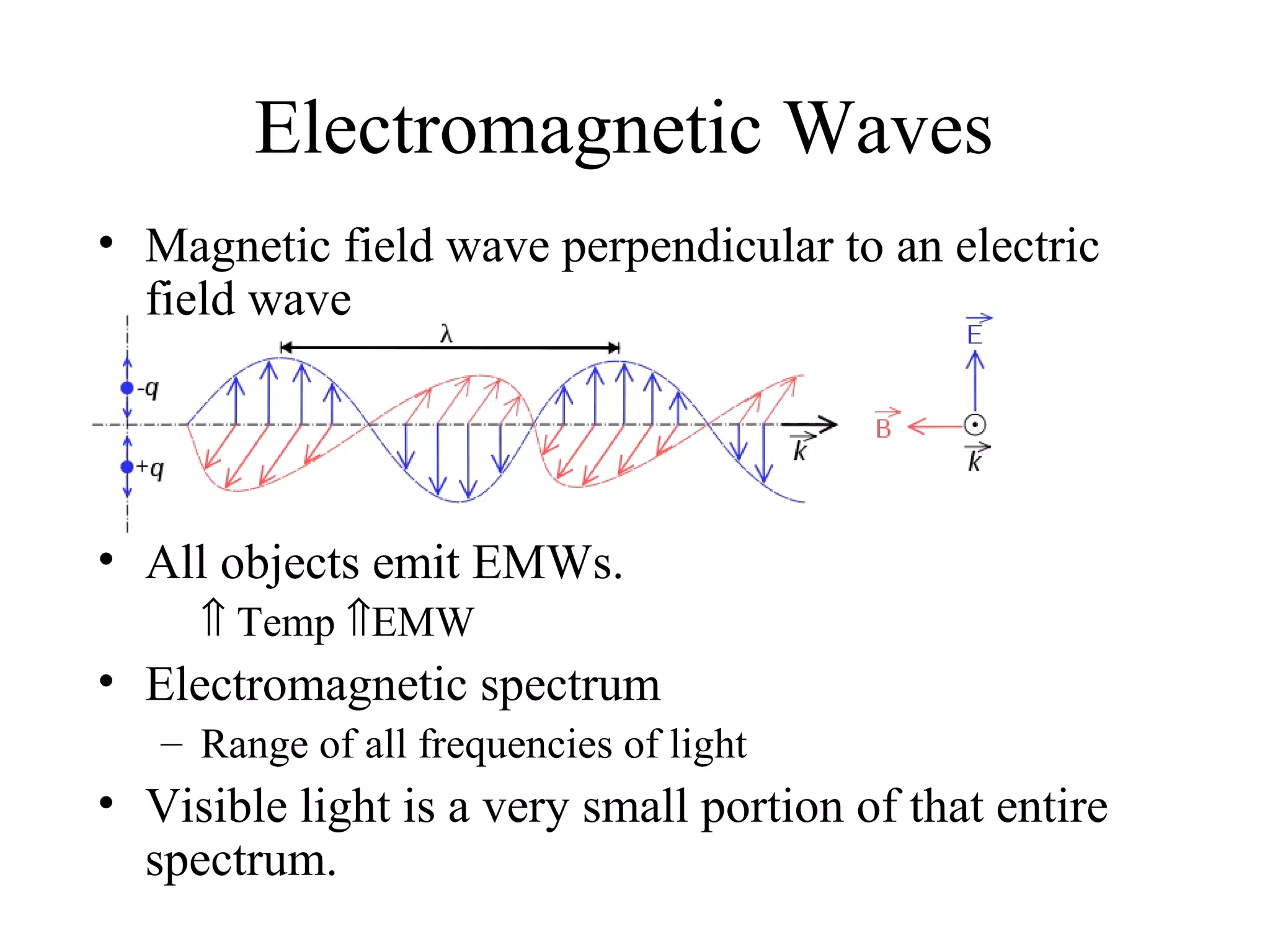
1) Light is an electromagnetic wave that travels in straight lines until it encounters a new medium, where it may be reflected or refracted depending on the medium's properties.
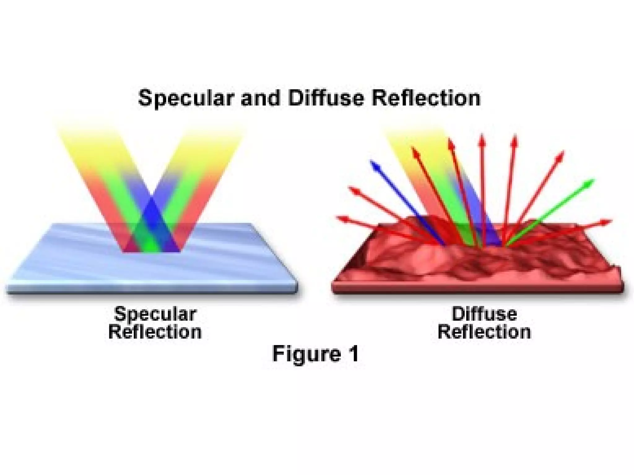
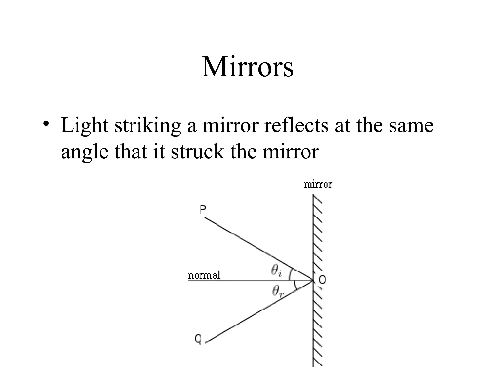
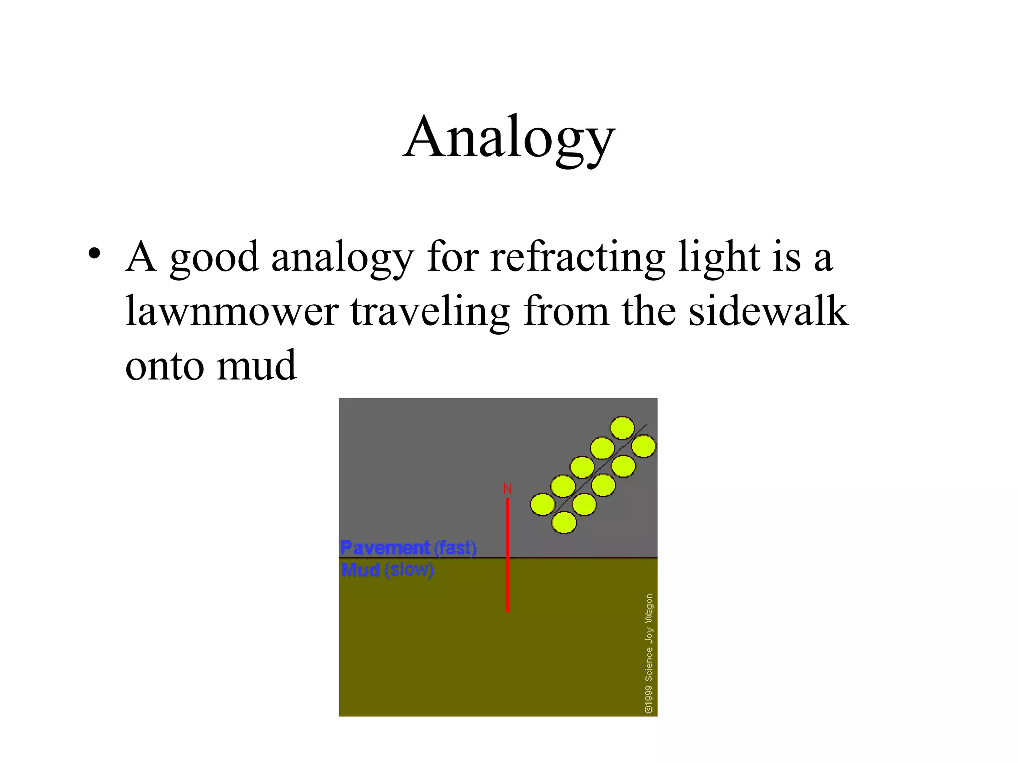
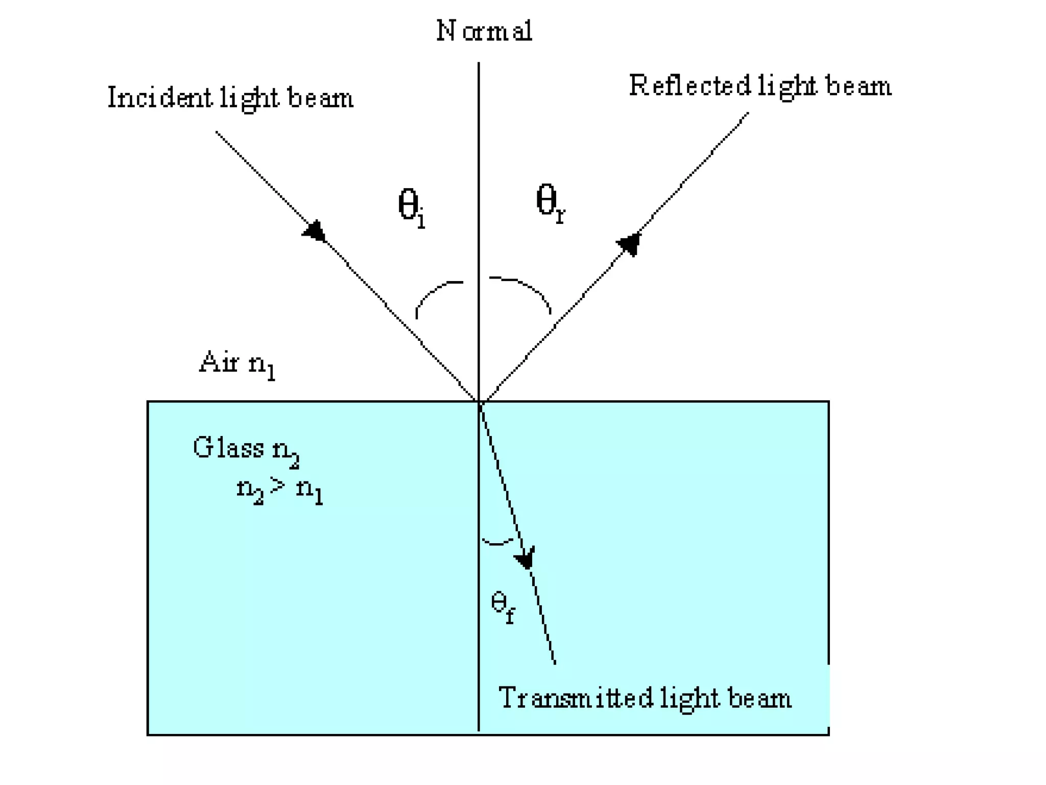
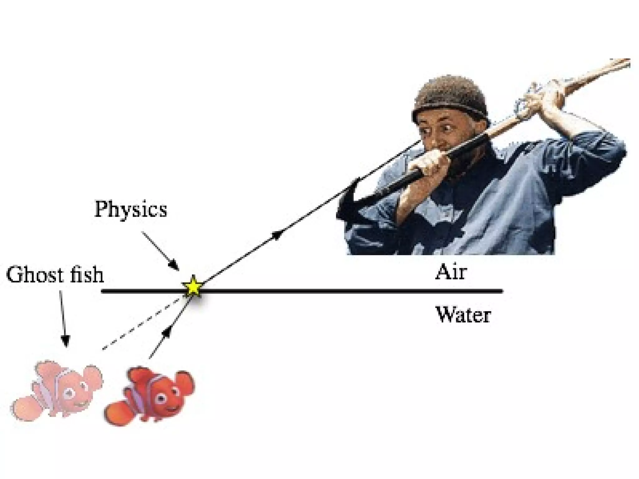
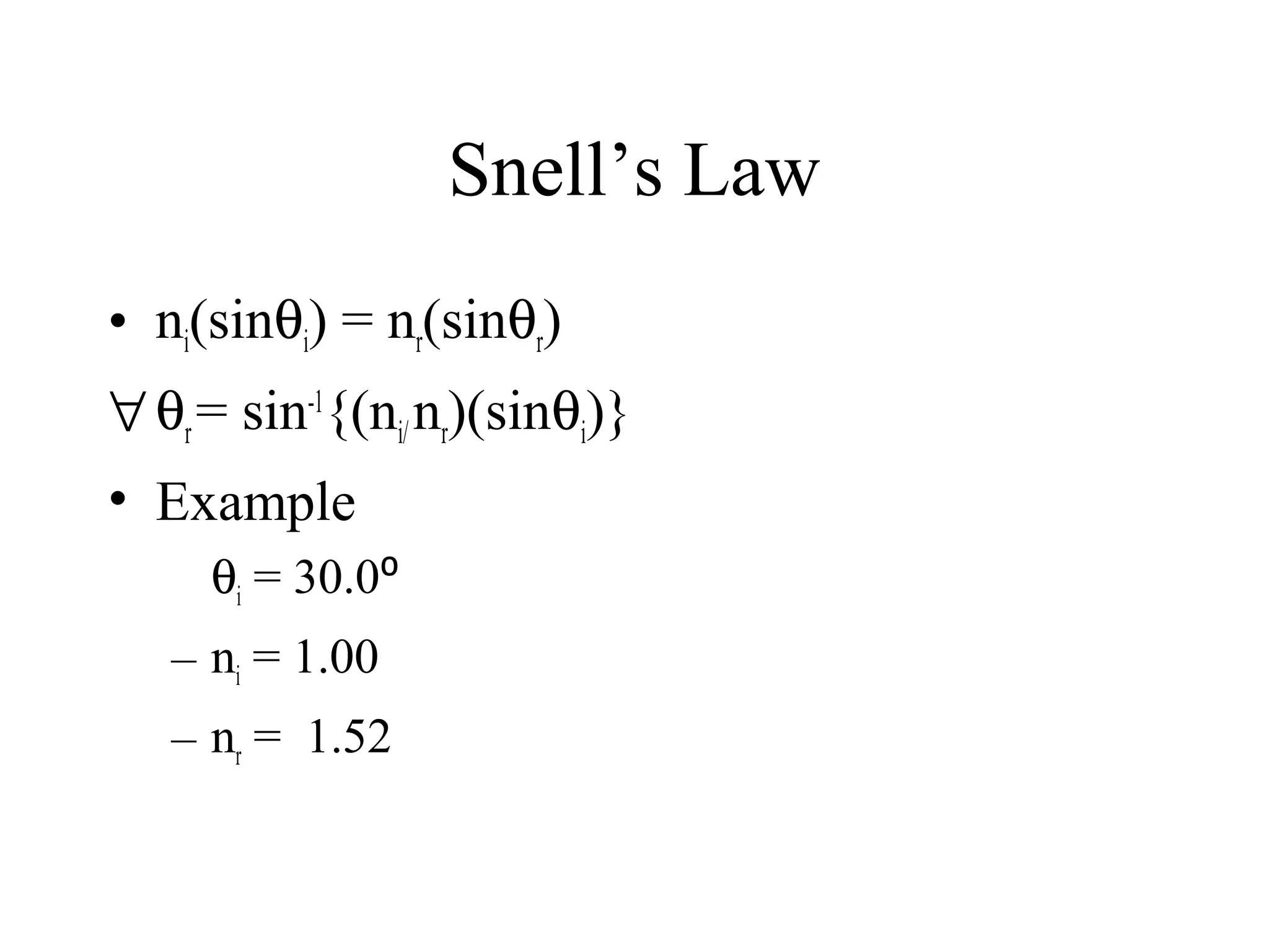
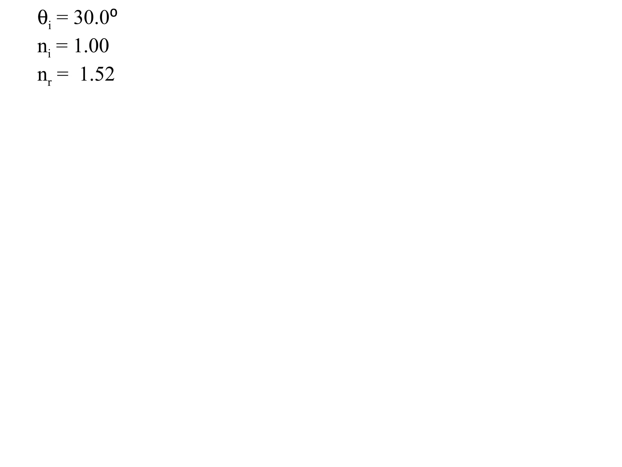
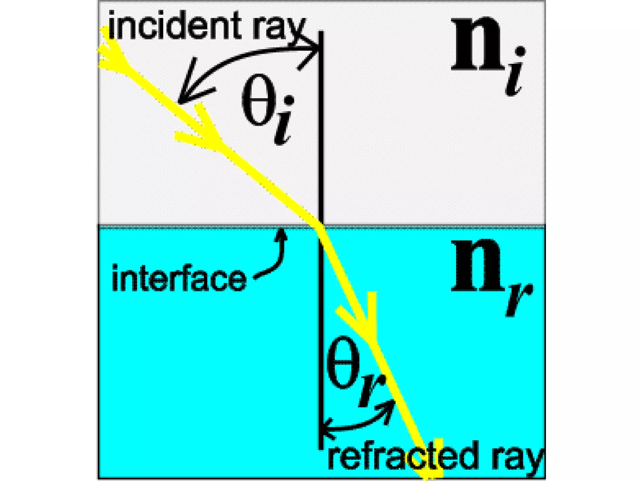
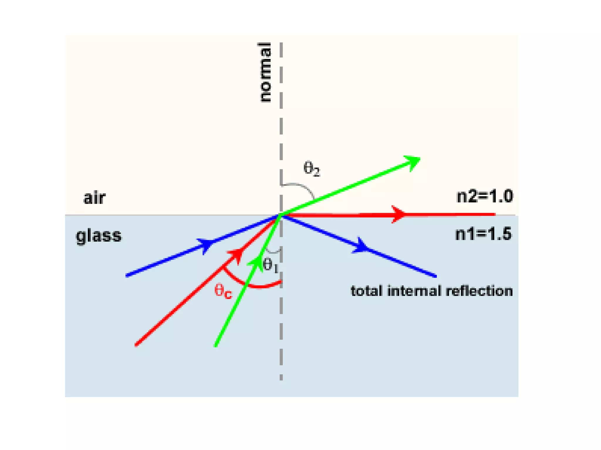
2) Reflection occurs when light changes direction upon striking an interface between two media, obeying the law that the angle of incidence equals the angle of reflection. Refraction is when light changes speed and direction when moving between media of different densities, governed by Snell's Law.
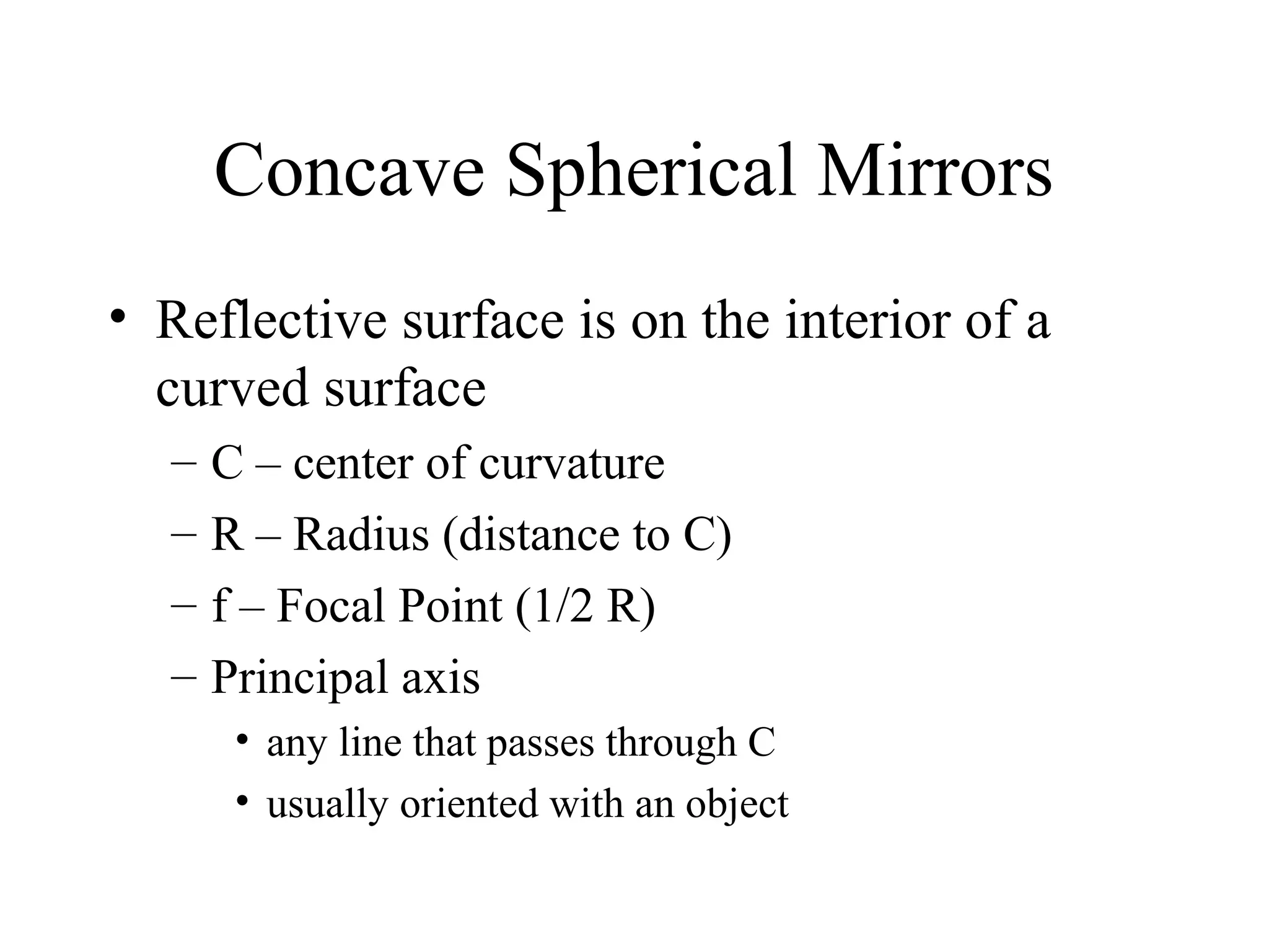
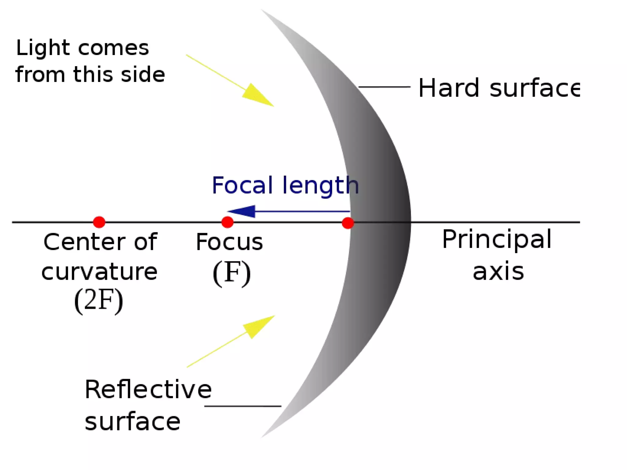
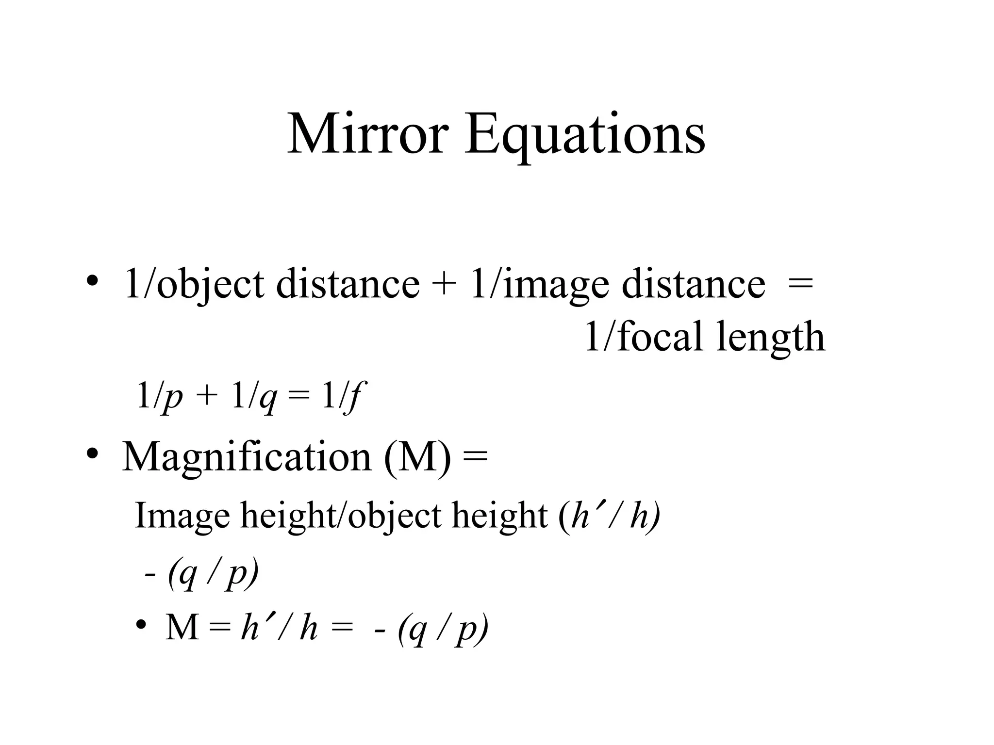
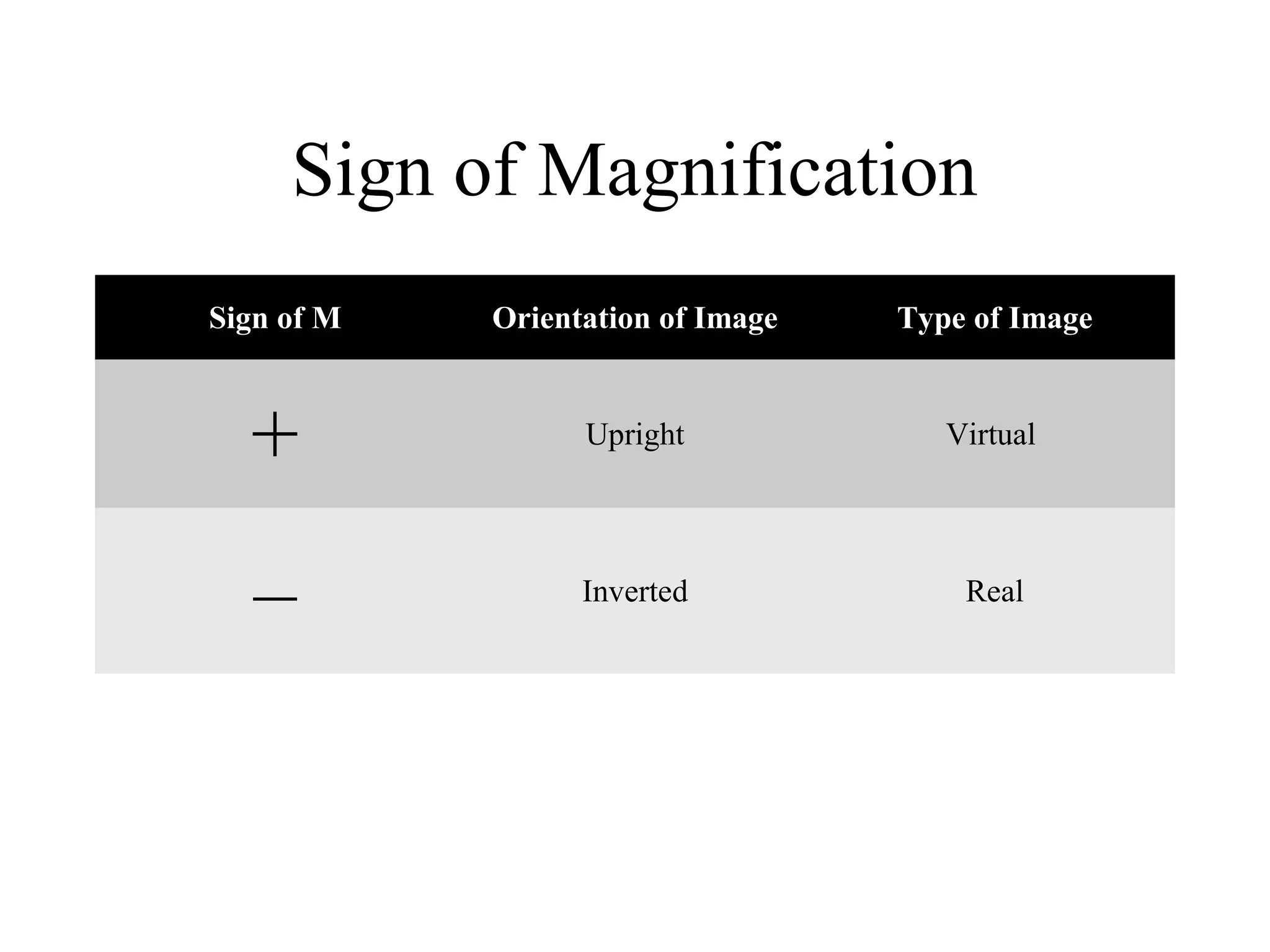
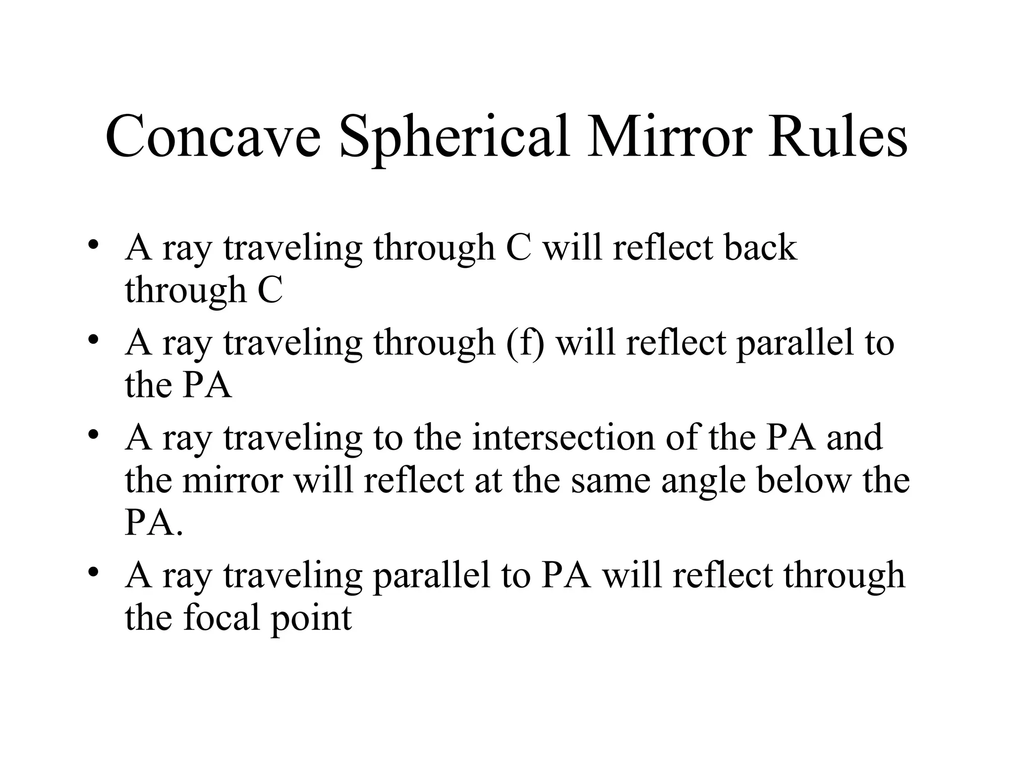
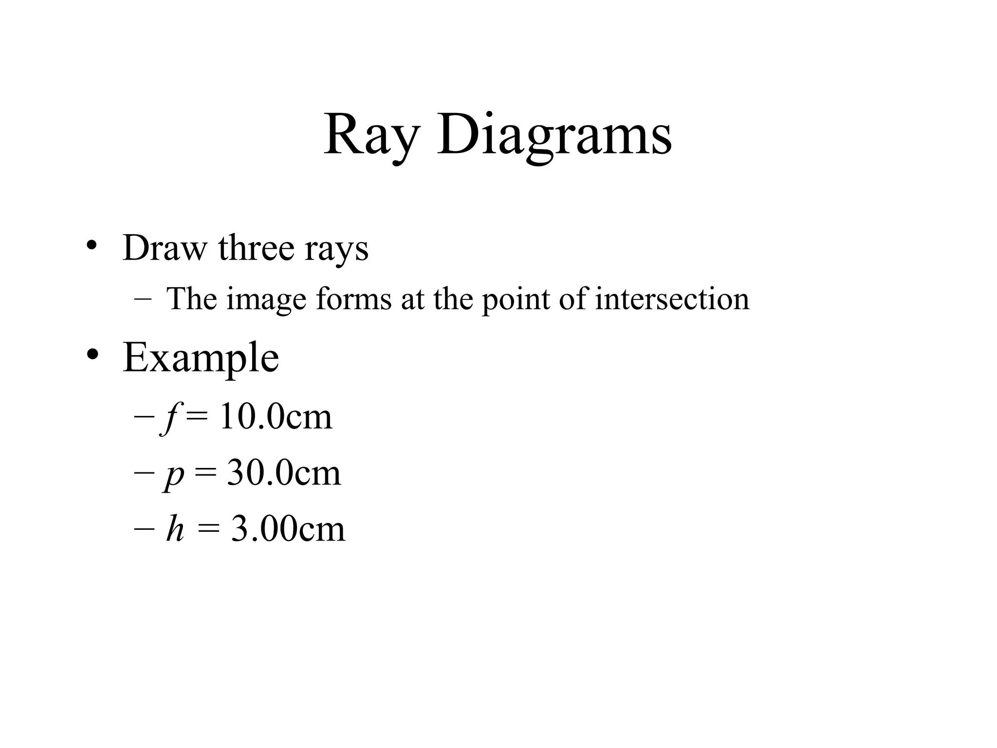
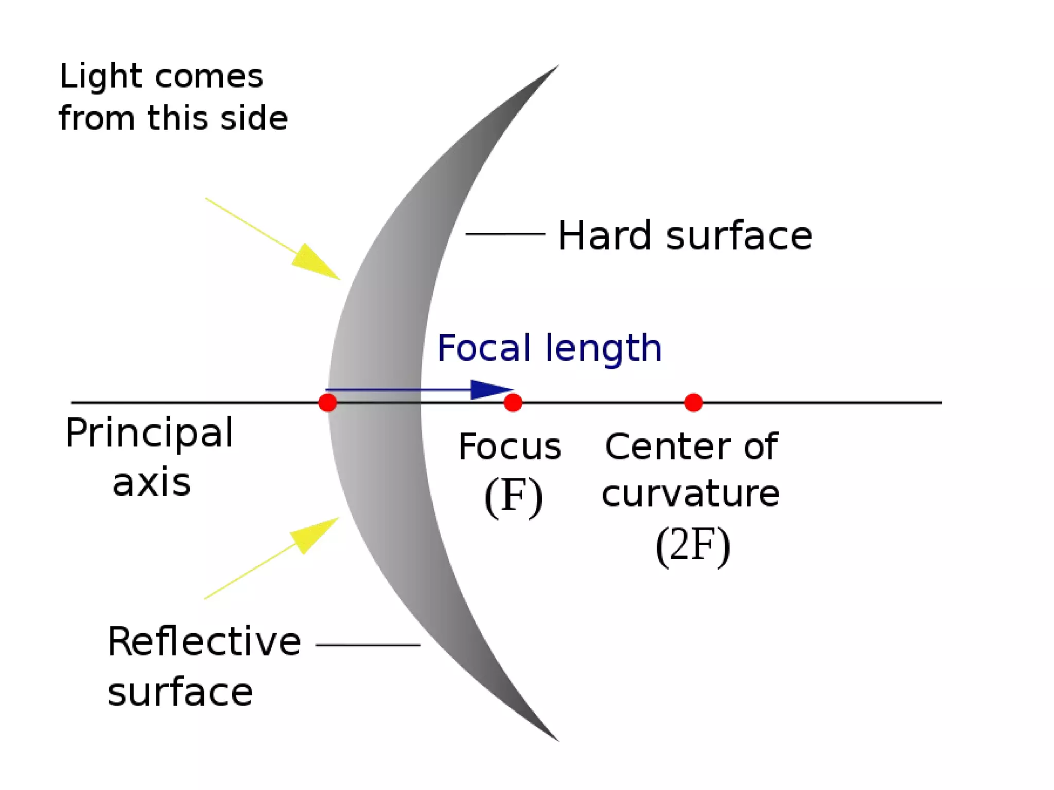
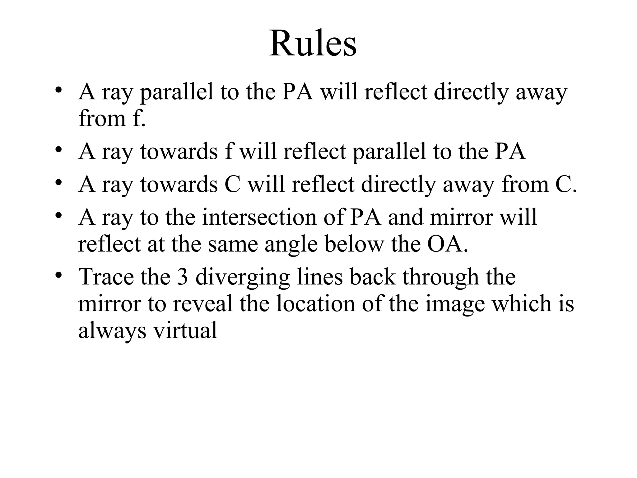
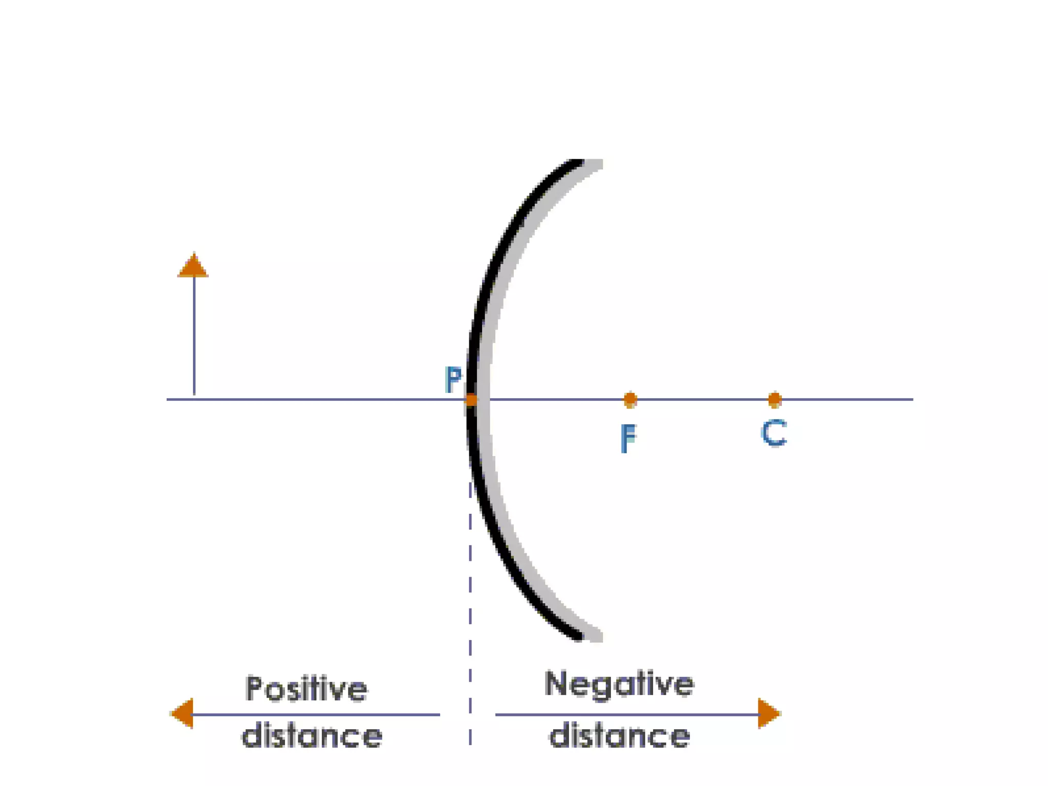
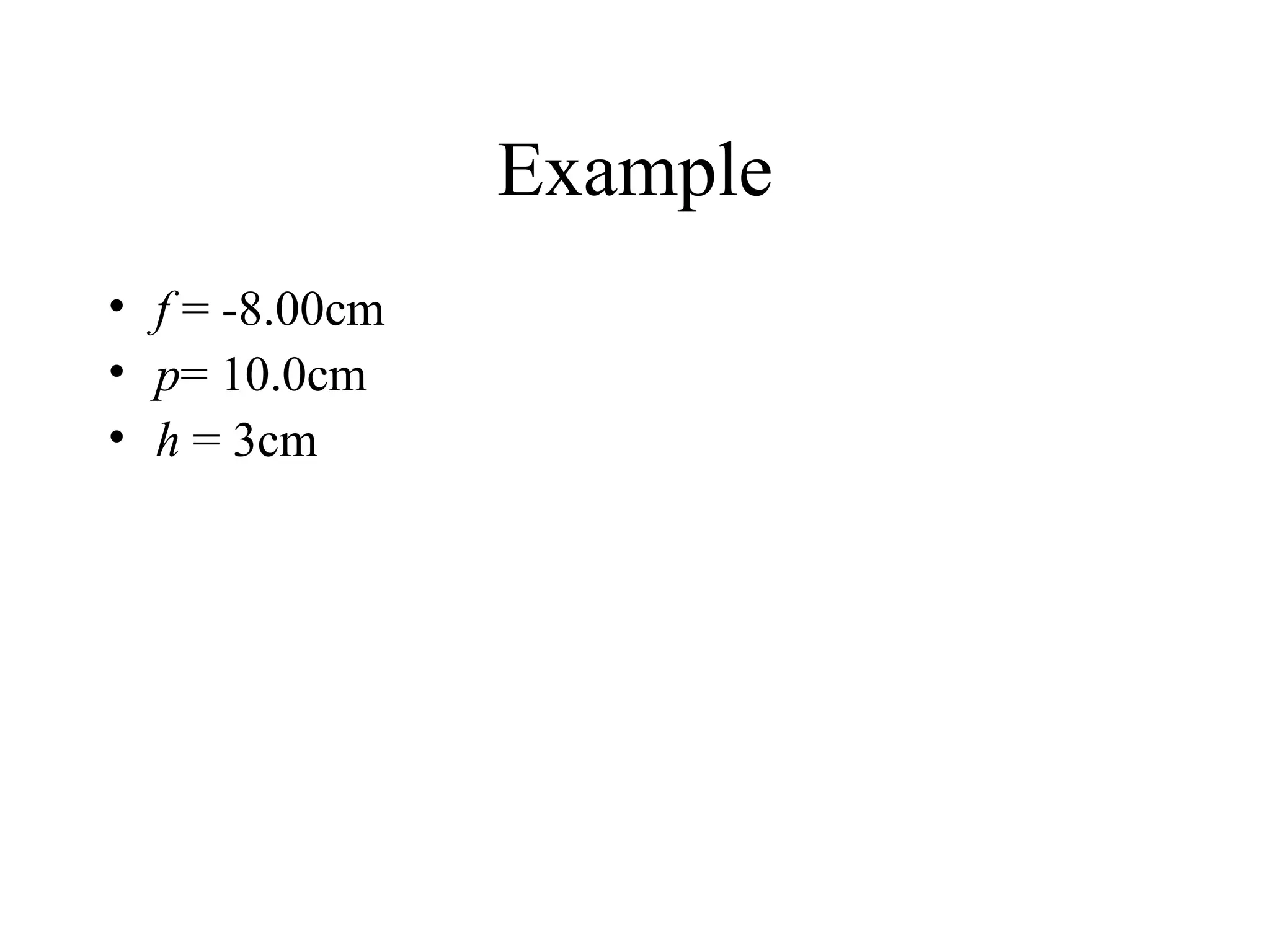
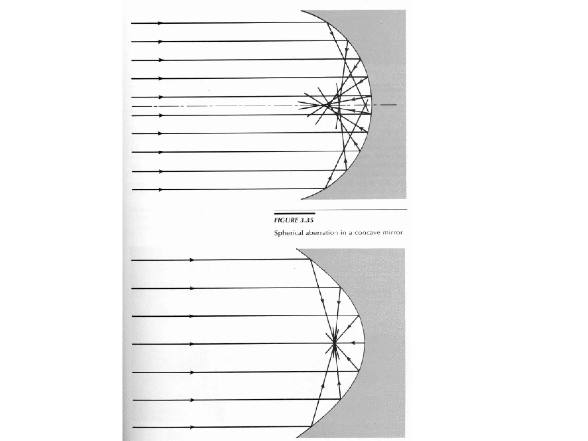
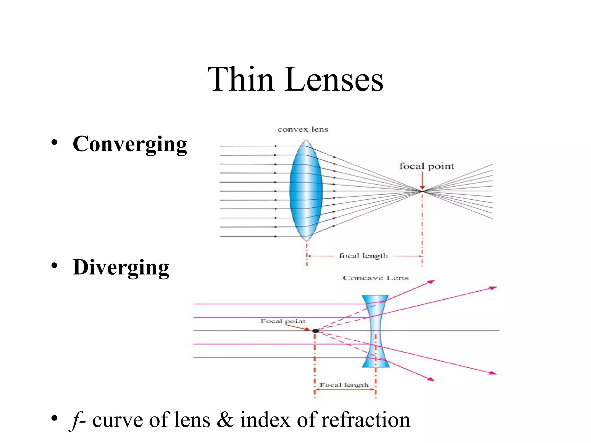
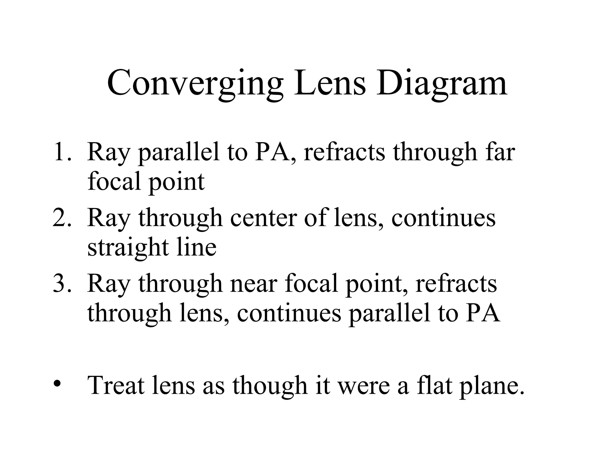
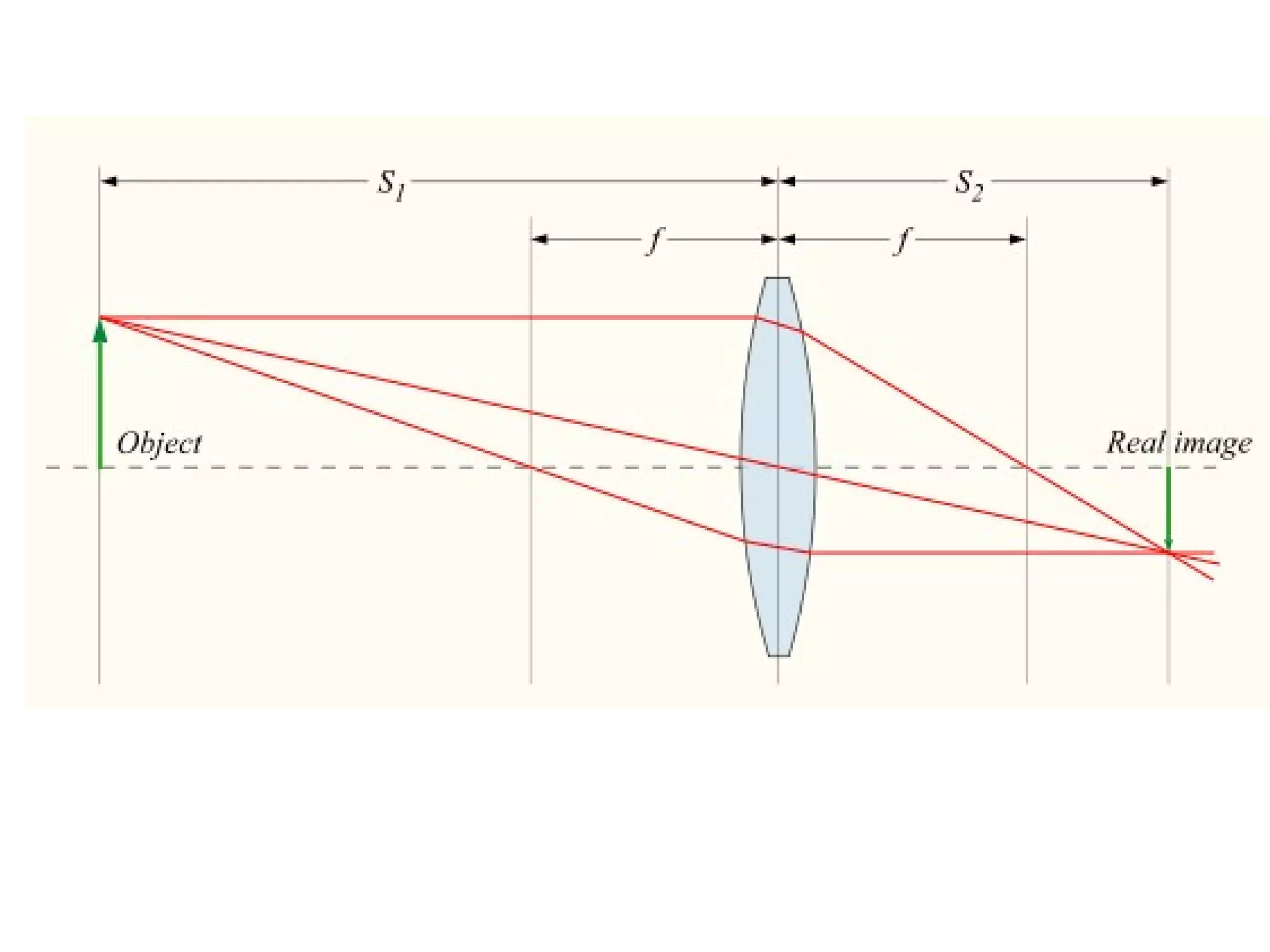
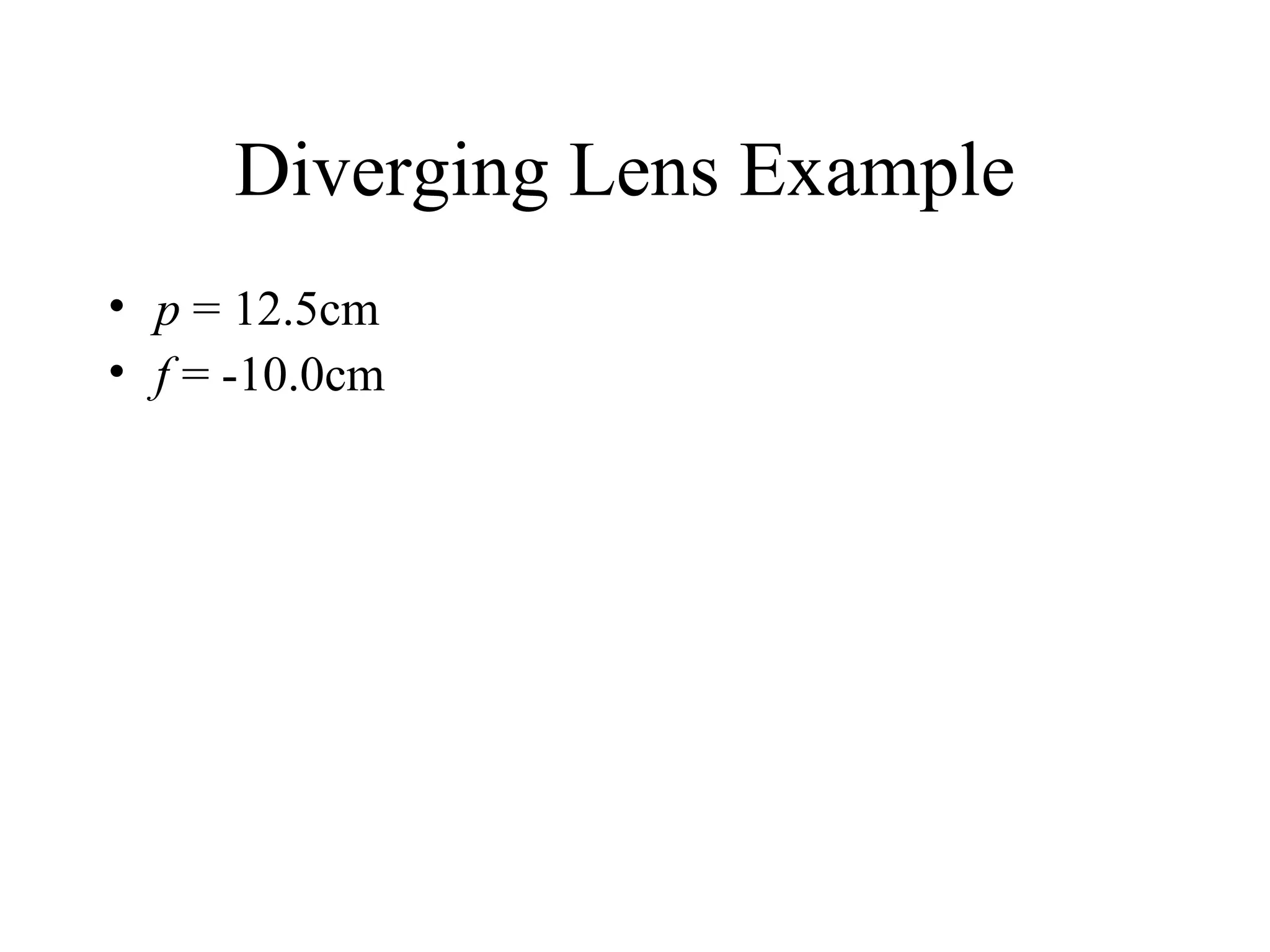
3) Lenses and mirrors can converge or diverge light via refraction or reflection, respectively, with their focusing power determined by their shape and the positioning of focal points and object/image distances following specific rules and equations.


![Coded Agents – with UiPath SDK + LangGraph [Virtual Hands-on Workshop]](https://cdn.slidesharecdn.com/ss_thumbnails/codedagentsdeck-251215155422-5497c599-thumbnail.jpg?width=640&height=640&fit=bounds)


