
Recommended
More Related Content
What's hot
What's hot (20)
Similar to Form Measurement Principles and Methods
Similar to Form Measurement Principles and Methods (20)
More from NatarajanGeetha
More from NatarajanGeetha (9)
Recently uploaded
Recently uploaded (20)
Form Measurement Principles and Methods
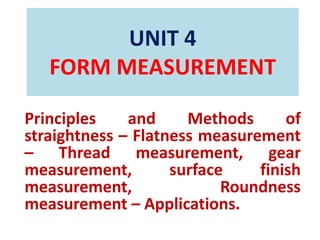
- 1. UNIT 4 FORM MEASUREMENT Principles and Methods of straightness – Flatness measurement – Thread measurement, gear measurement, surface finish measurement, Roundness measurement – Applications.
- 2. APPLICATIONS
- 8. INTRODUCTION • Threads are of prime importance, they are used as fasteners. • It is a helical groove, used to transmit force and motion. • In plain shaft, the hole assembly, the object of dimensional control is to ensure a certain consistency of fit. • The performance of screw threads during their assembly with nut depends upon a number of parameters such as the condition of the machine tool used for screw cutting, work material and tool.
- 9. GEOMETRICAL FEATURES • The measurement of • Straightness • Flatness • Squareness • Parallelism • Roundness • Circularity • Cylindricity
- 10. FORM MEASUREMENT INCLUDES • Screw thread measurement • Gear measurement • Radius measurement • Surface Finish measurement • Straightness measurement • Flatness measurement • roundness measurement
- 11. STRAIGHTNESS MEASUREMENT • A line is said to be straight over a given length, if the variation of the distance of its from two planes perpendicular to each other and parallel to the general direction of the line remains within the specified tolerance limits. • The tolerance on the straightness of a line is defined as the maximum deviation in relation to the reference straight line joining the two extremities of the line to be checked.
- 12. • Important geometrical parameter of machines • Example: shaping machine-guideways • Shortest distance between the two lines – straight line • Ray of light, liquid level • It is a qualitative measure of a surface • Straightness measuring system should be in line with functional point – called Bryan’s principle
- 14. METHODS OF STRAIGHTNESS SPIRIT LEVEL: • Inspecting the horizontal surfaces • Finding direction and magnitude of minor deviation from nominal condition • The bubble will move from its position along the radius of the angle of tilt. • Ether, alcohol, benzol- low viscosity fluid • Having graduated scale
- 18. STRAIGHT EDGES: • With the help of surface plates and sprit levels straight edges are used for checking straightness and flatness • Flat – sectioned measuring instrument • Made up of steels • Straight edges are used for testing large areas of surface • Painted surfaces are used to measure straightness LASER MEASURING SYSTEM:
- 20. FLATNESS MEASUREMENT • Minimum distance between the two planes, which will cover all irregularities of the surface to be tested • Best-fit plane between two standard reference plane one above and one below the plane surface to be tested • Deviation of the surface from the best fitting plane
- 22. TEST PROCEDURE
- 23. Measurement of Screw Threads • Screw Threads are used to Transmit power and Motion. • Fasten Two components with help Of nuts,bolts and Studs. Screw threads form included Angle,Head Angle,Helix angle.
- 26. Error In Thread
- 27. Error In Thread
- 28. Error In Thread
- 29. Error In Thread
- 30. Measurement of Various Elements of Thread 1.Major diameter 2.Minor Diameter. 3.Effective of Pitch diameter. 4.Pitch. 5.Thread Angle and form.
- 31. Measurement of Major Diameter • Ordinary Micrometer:
- 32. Measurement of Major Diameter • Bench Micrometer:
- 33. Measurement of Minor Diameter
- 34. Measurement of Minor Diameter
- 35. Measurement of Effective Diameter 1.One Wire Method. 2.Two Wire Method. 3.Three wire Method. 4.Micrometer Method. One Wire Method:
- 36. Measurement of Effective Diameter Two Wire Method:
- 37. Two Wire Method
- 44. Problems
- 49. THREAD MICROMETER METHOD • Used to measure threads within certain range of thread pitches. • Anvil settings getting small error to measure range threads. • First pitch diameter is measured for standard plug gauge of the same size. • It has special contacts to suit with the end screw thread for checking. • End of spindle is pointed at V thread from with corresponding V recess in the fixed Anvil. • Is to measure only the angle of point and flanks of the threads come into the contact. • Micometer give the pitch diameter. • Advantages: • Which shows the variation in drunken thread. • Limitations: • Must set Standard thread plug get reading exactly zero.
- 50. PITCH MEASUREMENT • Three methods, 1.Pitch Measuring Machine 2.Tool Makers microscope 3.Screw pitch gauge. Pitch Measuring Machine • Measurement is to move the stylus along the screen parallel to the axis from one place to the next place. • In this method is accurate method of measuring the pitch. • Micrometer reading is set near zero on the scale. • Indicator is moved along to bring the stylus and the indicator is adjusted radially.
- 51. Pitch Measuring Machine • Stylus engages between thread flanks and the pointer K is opposite in the line L. • To bring T in opposite in its index mark. • Rotation of the micrometer and the second reading is taken. • Difference between these two measured readings is known pitch of the thread.
- 52. Measurement of pitch TOOLMAKERS MICROSCOPE
- 54. 1.Work table is placed on the base of the instrument. 2.Optical Head is mounted on a vertical column it can be moved up and down. 3.Workpiece is mounted on glass plate. 4.Light source provides horizontal beam of light which reflected from a mirror 90° upward towards the table. 5.Image of the work piece through optical head. 6.Image is projected three prisms to ground glass. 7.Screen can be rotated 360 °. 8.Different types of graduated screens and eyepieces are used. Applications: Linear measurement. Measurement of Pitch diameter. Comparing thread forms. Center to center distance measurements.
- 55. THREAD GAUGES
- 56. Plug Screw Gauge
- 57. THREAD GAUGES
- 62. ADJUSTABLE THREAD GAUGES • It is another name of Wickman Adjustable Thread gauge. • Which is used to measure Limits,major,minor, and effective Diameter. • Anvil-Adjusting screw the setting of the master gauge. • After adjustment monogram lead seal can be fixed over the adjusting screw.
- 63. Gauging of Taps
- 64. Functions of Various types of gauges 1.Solid or Adjustable GO screw Ring gauge. 2.Check plug for new solid screw Ring gauge. 3.Wear Check plug for new solid and Adjustable GO Ring gauge. 4.Setting Plug for adjustable GO Screw Ring gauge. 5.GO screw Caliper Gauge. 6. Setting Plug for GO Screw Caliper gauge. 7.NOGO Screw Caliper gauge 8.Gauge for Major Diameter. Internal Thread gauging: 1.GO Screw Plug. 2.NOGO Screw Gauge 3.Gauge for Minor diameter.
- 66. FLOATING CARRIAGE MICROMETER • It consists of three major parts, 1.Base casting 2.Lower Carriage 3.Upper Carriage. • Base has housing to support the work piece. • Two V Grooves on the table lie parallel to the center.It’s support the Lower gauge. • Carriage has two conical pegs. • One V Grooves resting upon a ball. • Another one V Groove which lies on base ball. • Upper surface of the lower carriage has Two V grooves on ball bearings. • Upper carriage floats at freely on the balls.It is called Floating carriage. • Movement allowed two directions which right angle to each other.
- 67. Measurement of Gears • Gear is a mechanical drives which transmit power through toothed wheel. • Accuracy is very important to gear manufacturing. • Transmission efficiency almost 99%. • The gear blanks should be tested for the dimensional accuracy and tooth thickness for the forms of gears. • Two forms of gears are commonly.1.Involute 2.Cycloidal. • Involute gear is also called as spur gear. • Cycloidal gears are used to heavy and impact loads. • Pressure angle is 25° to 14.5°
- 68. Measurement of Gears Types of Gears: 1.Spur Gear. 2.Sprial Gear. 3.Helical Gear. 4.Bevel Gear. 5.Worm and worm wheel. 6.Rack and Pinion Gear.
- 69. Gear Terminology
- 70. Gear Terminology
- 71. Gear Terminology
- 72. Gear Terminology
- 73. Gears of Errors
- 74. Spur Gear Measurements Runout: • It is eccentricity in the pitch circle. • It will give the tooth failures in gears. • By used eccentricity tester. • Gears are rotates tooth by tooth and the variation is noted from the dial indicator.
- 75. Pitch Measurement 1.Tooth to Tooth Measurements 2.Direct Angular Measurement
- 78. Tooth Thickness Measurement A).GEAR TOOTH VERNIER CALIPER METHOD(CHORDAL THICKNESS METHOD)
- 81. B.BASE TANGENT METHOD C).CONSTANT CHORD METHOD
- 83. Parkinson Gear Tester • Master Gear attached the vertical Spindle. • Tested gear is fixed on carriage. • Carriage on slides on both sides. • Gear Rotates sliding carriage indicated by dial indicator.
- 84. Parkinson Gear Tester • Variation is recorded in a recorder by using waxed circular chart. • Mandrels are free rotates without clearance. • Left mandrels moves along Table. • Right mandrels moves along the Spring loaded carriage. • Scale is attached in one side and other side attached venirer which enables the center distance to be measured is 0.025mm. • Pitch or concentricity of pitch line is the errors. • Movement of carriage reading in dial indicator. • Errors are enables in gear tester. • The recorder is also filleted in the form of circular or rectangular chart, and than errors recorded. • Limitations:
- 85. Problems on Gear Measurement
- 88. Gleason gear testing machine
- 89. Rolling Gear Testing Machine
- 90. SURFACE FINISH MEASUREMENT • Components are produced by various method of manufacturing process. • It is not to possible to produce smooth surfaces and some irregularities are formed. • Factors affecting Surface finish Measurement. 1.Workpiece Material 2.Vibration 3.Machine Type 4.Too and fixtures.
- 91. Elements of surface texture
- 92. Elements of surface texture
- 93. Analysis of Surface Finish Types: 1.The Average of Roughness method. 2.Peak valley height method. 3.From Factor. The Average of Roughness method: i).Centre Line Average. ii).Root Mean square. iii).Ten Point Method.
- 94. Analysis of Surface Finish i).Centre Line Average.
- 95. Analysis of Surface Finish ii).Root Mean square.
- 96. Analysis of Surface Finish iii).Ten Point Method:
- 97. Analysis of Surface Finish 2.Peak valley height method.
- 98. Analysis of Surface Finish 3.Form factor: Form factor
- 99. Methods of measuring surface finish Types:1.Inspection by comparison method. 2.Direct instrument Method. 1.Inspection by comparison method.
- 100. Methods of measuring surface finish 2.Direct instrument Method i).Stylus Probe Instruments. ii).Tomlinson surface meter iii).Profilometer. iv).Taylor-Bobson-Talysurf i).Stylus Probe Instruments.
- 101. Methods of measuring surface finish ii).Tomlinson surface meter
- 102. Methods of measuring surface finish • iii).Profilometer
- 103. Methods of measuring surface finish iv).Taylor-Bobson-Talysurf
- 104. • Other methods of Measuring surface roughness: 1.Profilograph:
- 105. • Double Microscope:
- 106. Problems of Surface Roughness Measurement
- 109. 1.DIAMETERAL METHOD: • Measuring plungers are located 180° a part the diameter is measured at several places • It is suitable only specimen elliptical or it has an even number of lopes. • This method is unreliable in determining the roundness. 2.CIRCUMFERENTIAL CONFINING GAUGES: • This technique does not allow For the measurement of the other Related geometric characteristics, Such as concentrity,flatness of shoulders.
- 110. 3.Rotating on center: 4.V BLOCK
- 112. Adjustable V block: 5.Three Point Probe:
- 113. 6.Accurate Spindle:
- 118. Modern Roundness Measuring Instruments 1.Least Square circle. 2.Minimum zone or minimum radial seperation circle.
- 119. 3.Maximum inscribed circle. 4.Minimum circumscribed circles.