Download to read offline


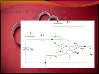
![Example #3 (con’t)
is = i1 + if
i = if
- i1 = i2
vd = v2 – v1 = Ri (- i1) = Ri (i2)
Vo= Avd - Ro(- i)
Vs= R1(is) – vd
Vs= R1(is) + Rf(if) + Vo
Vo/Vs = (-Rf/R1){Aβ/[1 +Aβ]}, where β = R1/(R1+Rf)](https://image.slidesharecdn.com/operational-amplifiers-160728215812/85/Operational-Amplifiers-Basic-25-320.jpg)


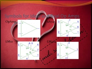
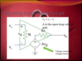
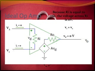
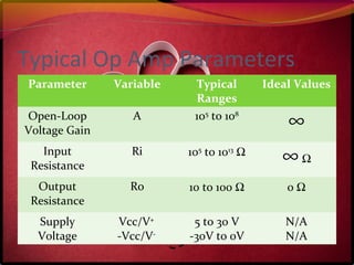
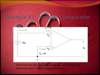
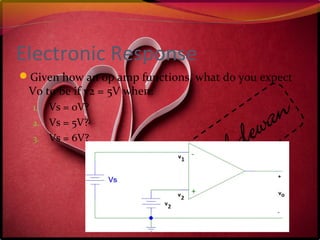
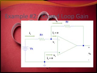
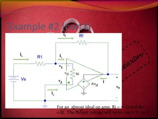
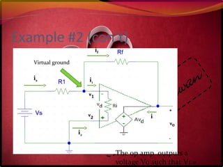
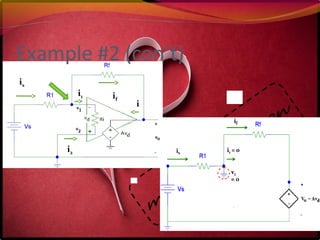
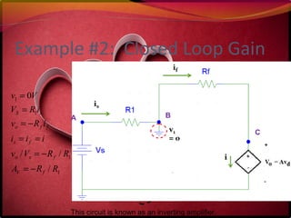
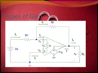
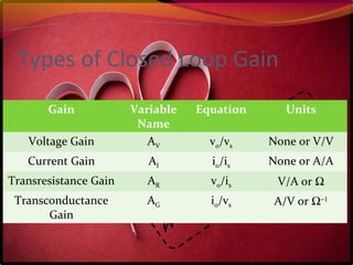
This document describes operational amplifiers (op amps) and their applications. It defines key parameters of ideal and real op amps like voltage gain, input resistance, and output resistance. Circuits like voltage comparators and inverting amplifiers are analyzed. The summary explains that an ideal op amp forces its input voltages to be equal while a real op amp output is limited between power supply voltages but still aims for zero difference between inputs. Common op amp applications include audio amplification, instrumentation, and analog computing.


