Download to read offline

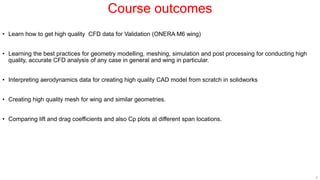


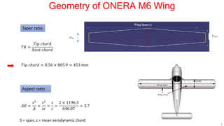
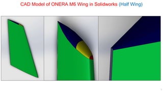
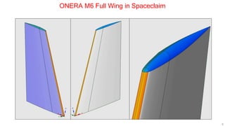
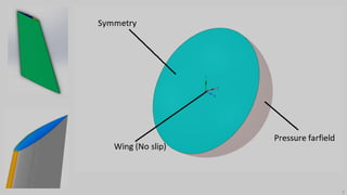
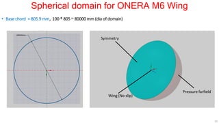
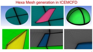
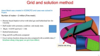
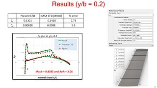
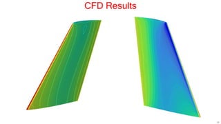

This document describes applying computational fluid dynamics (CFD) to analyze the aerodynamic flow over an ONERA M6 wing. It discusses modeling the wing geometry in CAD software, generating a hexahedral mesh, and simulating the flow in Fluent to validate results against experimental data. Key results include lift and drag coefficients that match the NASA CFD data to within 7.73% and 5.9% error respectively. Pressure coefficient plots along the wing also show good agreement with reference data. The course aims to teach best practices for CFD analysis and validation using the ONERA M6 wing test case.