М.Г.Гоман, А.В.Храмцовский, М.Шапиро «Разработка моделей аэродинамики и моделирование динамики самолета на больших углах атаки», доклад на международной конференции «Тренажерные технологии и обучение», прошедей в ЦАГИ, г.Жуковский, 24-25 мая 2001 г.
M.Goman, A.Khramtsovsky and M.Shapiro "Aerodynamics Modeling and Dynamics Simulation at High Angles of Attack", presentation at the International conference on Simulation Technology & Training held at TsAGI, Zhukovsky (Russia), on 24 May 2001.
ASSESSMENT OF AIRFRAME OVERLOADS OF AEROBATIC AIRCRAFTIAEME Publication
The paper presents the results of studies of statistical patterns of scattering of
overloads of aerobatic aircraft. The main parameters are the magnitude and repetition of
vertical overloads at the center of gravity for the two loading groups of the aerobatic
aircraft. Based on a statistical analysis of the values of equivalent vertical overloads for
each of the groups, correlation ratios were obtained for equivalent vertical overloads and
their repetition depending on the flight duration of the aircraft. The resulting solutions
allow us to predict the levels of damage occurring to the structure of a particular aircraft
for the total flight duration. Specific examples of comparative calculations of the
equivalent flying hours, as well as integral and differential repetition of aircraft in
formation and lead aircraft are considered.
Introduction to Airport Engineering Air craft characteristics affecting airport planning &
design, selection of site for an airport. Airports - layout and orientation, Runway and taxiway design
consideration and geometric design. Airport drainage management, Zoning laws, Visual aids and air
traffic control, Runway lighting, Runway operation Helipads, hangers, service equipment.
A Review of Flight Dynamics and Numerical Analysis of an Unmanned Aerial Vehi...Designage Solutions
A brief study of flight dynamics and different types of simulation and analysis are presented here.
Find case studies in my next PPT.- http://www.slideshare.net/HarshadaGurav/flight-dynamics-and-numerical-analysis-of-an-unmanned-aerial-vehicle-uav
Flight Dynamics and Numerical Analysis of an Unmanned Aerial Vehicle (UAV)Designage Solutions
Next part of "A Review of Flight Dynamics and Numerical Analysis of an Unmanned Aerial Vehicle (UAV)" with case studies.
Find previous presentation here- http://www.slideshare.net/HarshadaGurav/a-review-of-flight-dynamics-and-numerical-analysis-of-an-unmanned-aerial-vehicle-uav
Taking ground effect into account a longitudinal automatic landing system is designed. Such a system will be tested and implemented on board by using the Preceptor N3 Ultrapup aircraft which is used as technological demonstrator of new control navigation and guidance algorithms in the context of the “Research Project of National Interest” (PRIN 2008) by the Universities of Bologna, Palermo, Ferrara and the Second University of Naples. A general mathematical model of the studied aircraft has been built to obtain non–linear analytical equations for aerodynamic coefficients both Out of Ground Effect and In Ground Effect. To cope with the strong variations of aerodynamic coefficients In Ground Effect a modified gain scheduling approach has been employed for the synthesis of the controller by using six State Space Models. Stability and control matrices have been evaluated by linearization of the obtained aerodynamic coefficients. To achieve a simple structure of the control system, an original landing geometry has been chosen, therefore it has been imposed to control the same state variables during both the glide path and the flare.
Experimental investigation of stepped aerofoil using propeller test rigeSAT Publishing House
IJRET : International Journal of Research in Engineering and Technology is an international peer reviewed, online journal published by eSAT Publishing House for the enhancement of research in various disciplines of Engineering and Technology. The aim and scope of the journal is to provide an academic medium and an important reference for the advancement and dissemination of research results that support high-level learning, teaching and research in the fields of Engineering and Technology. We bring together Scientists, Academician, Field Engineers, Scholars and Students of related fields of Engineering and Technology.
Traditional use of Monocotyledon Plants of Arakuvalley Mandalam, Visakhapatna...IOSR Journals
An ethno-medico botanical survey of plants used in the treatment of different type of diseases of Arakuvalley Mandalam, Visakhapatnam district, Andhra Pradesh was conducted. The information was collected on the basis of personal interviews with traditional healers, tribal doctors and old women of the society. The investigation revealed that 34 Monocotyledon plant species belonging to 10 families and 28 genera are commonly used in the treatment of varies ailments
De-Noising Corrupted ECG Signals By Empirical Mode Decomposition (EMD) With A...IOSR Journals
The electrocardiogram (ECG) signals which are extensively used for heart disease diagnosis and patient monitoring are usually corrupted with various sources of noise. In this paper, an algorithm is developed to de-noise ECG signals based on Empirical Mode Decomposition (EMD) with application of Higher Order Statistics (HOS). The algorithm is applied on several ECG signals for different levels of Signal to Noise Ratio (SNR). The SNR improvement (SNRimp) and Percent Root mean square Difference (PRD (%)) are analyzed. The results show that the developed algorithm is a reasonable one to de-noise ECG signals.
Synthesis, Characterization and Application of Some Polymeric Dyes Derived Fr...IOSR Journals
In this study, Some Monoazo disperse dyes namely, 4-arylazoaminophenols (AAPs) were synthesized via diazotization and coupling reactions and later, polycondensation of these dyes with formaldehyde in the presence of aqueous oxalic acid was carried out. The resulting polymeric dyes namely, (4-arylazoaminophenol-formaldehyde)s (PAAP-F)s as well as their low-molecular weight precursors were characterized by yield, melting point, color, solubility, viscosimetry, Proton Nuclear Magnetic Resonance spectroscopy, UV-visible spectroscopy and Infra red spectroscopy. Their dyeing performance on nylon and polyester were assessed using standard methods. The products were obtained in good yield and had low melting points The dyes were found to be soluble in chloroform and acetone, some were found to dissolve in ethanol and methanol, and generally insoluble in water. The dyeing on nylon and polyester had yellow shades with moderate to good light and wash fastness. Their rubbing fastnesses on nylon and polyester were very good. Polymerizations of the monomeric dyes on dyed nylon and polyester have also been carried out. The dyeing properties of the monomeric and polymeric dyes were compared with the dyes polymerized in situ on nylon and polyester and the fastness properties were found to increase on polymerization and even better with the dyes polymerized inside the fibers
Spectral studies of 5-({4-amino-2-[(Z)-(2-hydroxybenzylidene) amino] pyrimidi...IOSR Journals
Some transition metal ions Complexes with 5-({4-amino-2-[(Z)-(2-hydroxybenzylidene) amino]
pyrimidin-5-yl} methyl)-2,3,4-trimethoxybenzene were prepared and characterized by elemental analyses,
Infrared , magnetic moment, electronic spectra , mass spectra, X-ray powder diffraction, molar conductance
and thermal analysis (TGA). The complexes have general formulae [ML2.2H2O] {where M = Mn (II), Co (II), Ni
(II), Cu (II), Zn (II), Pd (II) and Pt (II). The coordination behavior of the metal ions towards to the investigated
Schiff base takes place through –C=N,-NH2 and –OH groups. The obtained C, H and N elemental analysis data
showed the Metal: Ligand ratio is 1:2 [M: L] ratio. The molar conductance data reveal that all the metal
complexes are non-electrolytic in nature. From the magnetic moments the complexes are paramagnetic except
Zn metal ion complexes have octahedral geometry with coordination number eight. The thermal behavior of
these complexes shows that, the hydrated complexes have loses two water molecules and immediately followed
by decomposition of the anions and ligand molecules in the second and third stage. The Schiff bases and metal
complexes show good activity against some bacteria. The antimicrobial results indicate that, the metal
complexes have better antimicrobial activity as compared to the prepared Schiff base.
Combination of Cubic and Quartic Plane CurveIOSR Journals
The set of complex eigenvalues of unistochastic matrices of order three forms a deltoid.
A cross-section of the set of unistochastic matrices of order three forms a deltoid.
The set of possible traces of unitary matrices belonging to the group SU(3) forms a deltoid.
The intersection of two deltoids parametrizes a family of Complex Hadamard matrices of order six.
The set of all Simson lines of given triangle, form an envelope in the shape of a deltoid. This is known as the
Steiner deltoid or Steiner's hypocycloid after Jakob Steiner who described the shape and symmetry of the
curve in 1856.
The envelope of the area bisectors of a triangle is a deltoid (in the broader sense defined above) with
vertices at the midpoints of the medians. The sides of the deltoid are arcs of hyperbolas that are asymptotic
to the triangle's sides
Natural Radioactivity of Feed Coal and Its by-products in Barapukuria 2×125 M...IOSR Journals
The detection and measurement of radionuclides in feed coal, bottom ash and fly ash samples collected from Barapukuria 2×125 MW coal-fired thermal power plant in Dinajpur district of Bangladesh, have been performed by gamma ray spectrometry technique. The average activity concentrations of 226Ra, 232Th and 40K in feed coal, bottom ash and fly ash samples were 10.46±5.24, 23.50±10.88 and 232.23±131.94 Bqkg-1; 56.91±2.77, 69.22±4.26 and 189.79±64.65 Bqkg-1; and 70.91±2.90, 115.26±5.79 and 205.53±65.56 Bqkg-1; respectively. These measured values were compared with other literature values. The calculated absorbed dose rates were found higher than the worldwide average values for both the bottom ash and fly ash samples. Moreover, the radium equivalent activity in all the samples was less than 370 Bqkg-1 and external hazard indices were less than unity (except in FA-1). Therefore, there is no probability of immediate health effect on workers and public due to natural radioactivity present in the samples.
IOSR Journal of Humanities and Social Science is an International Journal edited by International Organization of Scientific Research (IOSR).The Journal provides a common forum where all aspects of humanities and social sciences are presented. IOSR-JHSS publishes original papers, review papers, conceptual framework, analytical and simulation models, case studies, empirical research, technical notes etc.
Structural Weight Optimization of Aircraft Wing Component Using FEM Approach.IJERA Editor
One of the main challenges for the civil aviation industry is the reduction of its environmental impact by better fuel efficiency by virtue of Structural optimization. Over the past years, improvements in performance and fuel efficiency have been achieved by simplifying the design of the structural components and usage of composite materials to reduce the overall weight of the structure. This paper deals with the weight optimization of transport aircraft with low wing configuration. The Linear static and Normal Mode analysis were carried out using MSc Nastran & Msc Patran under different pressure conditions and the results were verified with the help of classical approach. The Stress and displacement results were found and verified and hence arrived to the conclusion about the optimization of the wing structure.
Fabrication & installation of thorp t 211 wingAswin Shankar
Our main aim is to implement the composite materials to the thorp T-211 wing by fabrication of the carbon fiber and aramid fiber by the process of lapping of the sandwich panels.
In the initial stage of manufacturing of the thorp T-211 wing was done with the metals like aluminum. Aluminum has more strength, corrosion resistant and also less weight. So, aluminum has used in all aircraft parts.
But, now the technology has been increased in the material science. So, there is a new material has introduced in the field of materials. That is composite material these materials, Light weight, Resistance to corrosion, High resistance to fatigue damage, reduced machining Tapered sections and compound contours easily accomplished, Can orientate fibers in direction of strength/stiffness needed.
International Journal of Engineering Research and DevelopmentIJERD Editor
Electrical, Electronics and Computer Engineering,
Information Engineering and Technology,
Mechanical, Industrial and Manufacturing Engineering,
Automation and Mechatronics Engineering,
Material and Chemical Engineering,
Civil and Architecture Engineering,
Biotechnology and Bio Engineering,
Environmental Engineering,
Petroleum and Mining Engineering,
Marine and Agriculture engineering,
Aerospace Engineering.
Study of Aircraft Wing with Emphasis on Vibration CharacteristicsIJERA Editor
It is essential that the structural stability of the aircraft wings is a major consideration in the design of the aircraft. Many studies are being carried out for the design of the wings across the globe by the researches to strengthen the aircraft wings for steady and sturdy structures for dynamic conditions. The design of the aircraft wing using NACA standards is been discussed in this work. The wing analysis is carried out by using computer numerical analysis tool, viz., CAD/CAE and CFD. The necessary inputs for carrying out the structural analysis with emphasis on the vibration are obtained by CFD analysis. The deformation of the wing structures are investigated with respect to the standard airflow velocity. The velocity of air at the inlet is taken as 122 m/s (438 km/h), considering service ceiling of 7625 m at moderate temperature. The modal analysis is considered to analyse the wing to determine the natural frequency for vibration characteristics of the wing structure. The study of the effect of the stresses and deformations of the wing structure on the vibration characteristics of the wing is carried out to understand the effect of stress on natural frequency of the aircraft wing structure. Hence it is possible to correlate the effect of wind pressure on the vibration of the wing structure for particular design of the wing (NACA). The CFD results revealed that the pressure on the upper surface of the wing for all the wing section planes (butt planes-BL) is less, about -4.97e3N/mm2, as compared to the pressure on the lower surface, about 1.08e4 N/mm2, which satisfy the theory of lift generation. The pre-stressed modal analysis shows the correlation of the stress, deformation and the corresponding mode of vibration. It is found that the maximum deformation of 17.164 mm is corresponding to the modal frequency of 179.65 Hz which can be considered as design frequency of the wing structure. However the fundamental natural frequency of the wing structure is 10.352 Hz for the deformation of 11.383 mm.
Technical Development of Design & Fabrication of an Unmanned Aerial VehicleIOSR Journals
: UAV (Unmanned Aerial Vehicle) is an air vehicle which is largely used for surveillance, monitoring,
reconnaissance, data relay, and data collection or to enter the area which is not safe for human i.e. flood
affected or virus affected area. This paper represents the unique design of such an UAV which designed at
MILITARY INSTITUTE OF SCIENCE & TECHNOLOGY to participate in an international competition SAE
Aero Design West-2013. As per competition requirement empty weight of the UAV must be less than 2 lb and
must fly with payload as heavy as possible for good scoring. Initially, the model of the UAV was tested in wind
tunnel and the test data showed that the model aircraft performance was capable enough for flying and covering
an area specified in the competition. Subsequently, an actual aircraft was fabricated of that model and flight
tested which proved the match with theoretical, statistical and experimental data that was obtained from wind
tunnel test, wing tip test, tensile test of manufacturing material and CFD (Computational Fluid Dynamics) flow
simulation over the aerofoil.
Flow Anlaysis on Hal Tejas Aircraft using Computational Fluid Dynamics with D...IJAEMSJORNAL
In the current globalization, we can see many innovations being introduced or implemented in every aspect of field that are considered to be existed. Every country is aiming to develop its power over all the aspects that considered for comparison with other countries in order to stand at same level of competition with others. One such power considered by all countries to develop every possible way to have a healthy competition is the military power which involves basically innovations of fast moving aircraft having a high lift coefficient and low drag coefficient. Such an aircraft having the high lift and low drag coefficient is TEJAS (HAL) developed by country India on which the purpose of paper mainly sustains. The paper mainly focuses on steady-state flow analysis over aircraft TEJAS using the computer aided modelling techniques and also the comparison of the results obtained from the modelled techniques. The paper also outlines the designing of the structural model of the TEJAS in a modelling software, creation of a finite computational domain, segmentation of this domain into discrete intervals, applying boundary conditions such as velocity in order to obtain plots and desired results determining the coefficient of pressure, lift and drag coefficient, velocity magnitude etc. This paper also aims in creating awareness to the future students about the techniques involved and knowledge required for developing a designed modelled. This paper also highlights the use of CFD techniques involved for the purpose of fluid flow simulation of the aircraft especially performing the meshing techniques, pre and post processing techniques and finally the evaluation of the simulation. Finally this paper can be seen as source by future generation students in gaining knowledge about design, analysis and simulation of the structured model on various conditions, about the field of aerospace engineering and new innovations being developed and also about the career involved when the above fields were chosen foe specialization purposes
Kubernetes & AI - Beauty and the Beast !?! @KCD Istanbul 2024Tobias Schneck
As AI technology is pushing into IT I was wondering myself, as an “infrastructure container kubernetes guy”, how get this fancy AI technology get managed from an infrastructure operational view? Is it possible to apply our lovely cloud native principals as well? What benefit’s both technologies could bring to each other?
Let me take this questions and provide you a short journey through existing deployment models and use cases for AI software. On practical examples, we discuss what cloud/on-premise strategy we may need for applying it to our own infrastructure to get it to work from an enterprise perspective. I want to give an overview about infrastructure requirements and technologies, what could be beneficial or limiting your AI use cases in an enterprise environment. An interactive Demo will give you some insides, what approaches I got already working for real.
Elevating Tactical DDD Patterns Through Object CalisthenicsDorra BARTAGUIZ
After immersing yourself in the blue book and its red counterpart, attending DDD-focused conferences, and applying tactical patterns, you're left with a crucial question: How do I ensure my design is effective? Tactical patterns within Domain-Driven Design (DDD) serve as guiding principles for creating clear and manageable domain models. However, achieving success with these patterns requires additional guidance. Interestingly, we've observed that a set of constraints initially designed for training purposes remarkably aligns with effective pattern implementation, offering a more ‘mechanical’ approach. Let's explore together how Object Calisthenics can elevate the design of your tactical DDD patterns, offering concrete help for those venturing into DDD for the first time!
Essentials of Automations: Optimizing FME Workflows with ParametersSafe Software
Are you looking to streamline your workflows and boost your projects’ efficiency? Do you find yourself searching for ways to add flexibility and control over your FME workflows? If so, you’re in the right place.
Join us for an insightful dive into the world of FME parameters, a critical element in optimizing workflow efficiency. This webinar marks the beginning of our three-part “Essentials of Automation” series. This first webinar is designed to equip you with the knowledge and skills to utilize parameters effectively: enhancing the flexibility, maintainability, and user control of your FME projects.
Here’s what you’ll gain:
- Essentials of FME Parameters: Understand the pivotal role of parameters, including Reader/Writer, Transformer, User, and FME Flow categories. Discover how they are the key to unlocking automation and optimization within your workflows.
- Practical Applications in FME Form: Delve into key user parameter types including choice, connections, and file URLs. Allow users to control how a workflow runs, making your workflows more reusable. Learn to import values and deliver the best user experience for your workflows while enhancing accuracy.
- Optimization Strategies in FME Flow: Explore the creation and strategic deployment of parameters in FME Flow, including the use of deployment and geometry parameters, to maximize workflow efficiency.
- Pro Tips for Success: Gain insights on parameterizing connections and leveraging new features like Conditional Visibility for clarity and simplicity.
We’ll wrap up with a glimpse into future webinars, followed by a Q&A session to address your specific questions surrounding this topic.
Don’t miss this opportunity to elevate your FME expertise and drive your projects to new heights of efficiency.
GDG Cloud Southlake #33: Boule & Rebala: Effective AppSec in SDLC using Deplo...James Anderson
Effective Application Security in Software Delivery lifecycle using Deployment Firewall and DBOM
The modern software delivery process (or the CI/CD process) includes many tools, distributed teams, open-source code, and cloud platforms. Constant focus on speed to release software to market, along with the traditional slow and manual security checks has caused gaps in continuous security as an important piece in the software supply chain. Today organizations feel more susceptible to external and internal cyber threats due to the vast attack surface in their applications supply chain and the lack of end-to-end governance and risk management.
The software team must secure its software delivery process to avoid vulnerability and security breaches. This needs to be achieved with existing tool chains and without extensive rework of the delivery processes. This talk will present strategies and techniques for providing visibility into the true risk of the existing vulnerabilities, preventing the introduction of security issues in the software, resolving vulnerabilities in production environments quickly, and capturing the deployment bill of materials (DBOM).
Speakers:
Bob Boule
Robert Boule is a technology enthusiast with PASSION for technology and making things work along with a knack for helping others understand how things work. He comes with around 20 years of solution engineering experience in application security, software continuous delivery, and SaaS platforms. He is known for his dynamic presentations in CI/CD and application security integrated in software delivery lifecycle.
Gopinath Rebala
Gopinath Rebala is the CTO of OpsMx, where he has overall responsibility for the machine learning and data processing architectures for Secure Software Delivery. Gopi also has a strong connection with our customers, leading design and architecture for strategic implementations. Gopi is a frequent speaker and well-known leader in continuous delivery and integrating security into software delivery.
Slack (or Teams) Automation for Bonterra Impact Management (fka Social Soluti...Jeffrey Haguewood
Sidekick Solutions uses Bonterra Impact Management (fka Social Solutions Apricot) and automation solutions to integrate data for business workflows.
We believe integration and automation are essential to user experience and the promise of efficient work through technology. Automation is the critical ingredient to realizing that full vision. We develop integration products and services for Bonterra Case Management software to support the deployment of automations for a variety of use cases.
This video focuses on the notifications, alerts, and approval requests using Slack for Bonterra Impact Management. The solutions covered in this webinar can also be deployed for Microsoft Teams.
Interested in deploying notification automations for Bonterra Impact Management? Contact us at sales@sidekicksolutionsllc.com to discuss next steps.
Transcript: Selling digital books in 2024: Insights from industry leaders - T...BookNet Canada
The publishing industry has been selling digital audiobooks and ebooks for over a decade and has found its groove. What’s changed? What has stayed the same? Where do we go from here? Join a group of leading sales peers from across the industry for a conversation about the lessons learned since the popularization of digital books, best practices, digital book supply chain management, and more.
Link to video recording: https://bnctechforum.ca/sessions/selling-digital-books-in-2024-insights-from-industry-leaders/
Presented by BookNet Canada on May 28, 2024, with support from the Department of Canadian Heritage.
Software Delivery At the Speed of AI: Inflectra Invests In AI-Powered QualityInflectra
In this insightful webinar, Inflectra explores how artificial intelligence (AI) is transforming software development and testing. Discover how AI-powered tools are revolutionizing every stage of the software development lifecycle (SDLC), from design and prototyping to testing, deployment, and monitoring.
Learn about:
• The Future of Testing: How AI is shifting testing towards verification, analysis, and higher-level skills, while reducing repetitive tasks.
• Test Automation: How AI-powered test case generation, optimization, and self-healing tests are making testing more efficient and effective.
• Visual Testing: Explore the emerging capabilities of AI in visual testing and how it's set to revolutionize UI verification.
• Inflectra's AI Solutions: See demonstrations of Inflectra's cutting-edge AI tools like the ChatGPT plugin and Azure Open AI platform, designed to streamline your testing process.
Whether you're a developer, tester, or QA professional, this webinar will give you valuable insights into how AI is shaping the future of software delivery.
Smart TV Buyer Insights Survey 2024 by 91mobiles.pdf91mobiles
91mobiles recently conducted a Smart TV Buyer Insights Survey in which we asked over 3,000 respondents about the TV they own, aspects they look at on a new TV, and their TV buying preferences.
Empowering NextGen Mobility via Large Action Model Infrastructure (LAMI): pav...
N1303047887
1. IOSR Journal of Mechanical and Civil Engineering (IOSR-JMCE)
e-ISSN: 2278-1684,p-ISSN: 2320-334X, Volume 13, Issue 3 Ver. IV (May- Jun. 2016), PP 78-87
www.iosrjournals.org
DOI: 10.9790/1684-1303047887 www.iosrjournals.org 78 | Page
Conceptual design, Structural and Flow analysis of an UAV wing
Abdus Samad Shohan 1
, G.M. Asif Ahmed 2
, Fahad Alam Moon3
,
Wing Commander S A Savanur4
1, 2, 3(Department of Aeronautical Engineering, Military Institute of Science & Technology, Dhaka-1216,
Bangladesh
4(Associate Professor, Department of Aeronautical Engineering, Military Institute of Science & Technology,
Dhaka-1216, Bangladesh
Abstract: Unmanned Aerial Vehicles (UAVs) are considered as the largest integration of modern technology
which have enormous potential for both military special operations & civil applications. UAVs are often
preferred for missions that are too "dull, dirty, and dangerous". Its efficiency & success depends on factors such
as performance, maintenance costs, design etc. This Paper aims to optimize the design of the wing of a medium
size surveillance type UAV, by carrying out both analytical and computational analysis of aerodynamic and
structural loads & also to study various materials and techniques for the fabrication of the designed wing.
During the study, an attempt was made to familiarize with the theoretical aerodynamics, aircraft structural
design methodologies and historical trends in wing design. The preliminary design dimensions as well as
relevant loads of the wing structure were calculated based on the design lift and loading requirement for the
UAV. The wing design was further analyzed by creating a software model of the UAV wing and simulating the
flow and the structural loads using Solid Works and Design Foil software packages. The study attempts to
record the steps followed, the calculations done, the theories applied and the references used during the project
in a gradual progression to aid any future developmental work or study on wing design. The simplified
analytical development of the conceptual design of a UAV wing can be used as a design reference for other
types of aircrafts in some generic point of view.
Keywords: Solidworks, simulation, airfoil, design, wing, control surface etc.
I. Introduction
An UAV is defined as a "powered, aerial vehicle which does not carry a human operator, uses
aerodynamic forces to provide vehicle lift, can fly autonomously based on pre-programmed flight plans or more
complex dynamic automation systems, or be piloted remotely, can be expendable or recoverable, and can carry a
lethal or nonlethal payload [1]. Its aircrew is removed and replaced by a computer system and a radio link. In
contrast to general aviation, UAVs have taken the pivotal point in certain autonomous operations including:
military task execution, aerial renaissance, aerial survey and rescue, crop management and numerous remotely
piloted operations.UAV has been in the zone of curiosity of aeronautics for last several decades. However,
contrary to the manned aircraft, empirical sources of data for UAVs are not well enriched. This report focuses
on building up a topological base for the conceptualize design of the wing of a “Medium Size Surveillance” type
UAV and supporting this base with linear static and computational fluid dynamics analysis. This report proposes
selection of suitable wing construction material, latter on the report. Conceptual design of the wing deals with
wing shape and relevant characteristics. The objective of this report is to provide perspicacity on wing
parameters, layout, construction, aerodynamic characteristics, responses to load, behavior of the fluid flow
around it and simplified idea of construction. This report focuses on converging to a suitable design for the
given mission requirement. To optimize the solution two different design perspectives are going to be
approached; wing with tubular spar and wing with I-beam spar. Methodical procedures are followed to obtain
various wing parameters. Static structural analysis using Solidworks provides optimum selection of ribs and
flow simulation on over the wing is discussed later on the study.
1.1 Design Requirements and parameters
These parameters are taken comparing with global specifications to conceptualize the wing design[1].
Parameters Units
Empty weight 78.622 lbs.
Payload 5 lbs.
Fuel weight 16.377 lbs.
Overall weight 100 lbs.
Range 4.5 km
Endurance 2.5 hrs.
Altitude 8000 ft.
Table 1-list of physical parameters
2. Conceptual design, Structural and Flow analysis of an UAV wing
DOI: 10.9790/1684-1303047887 www.iosrjournals.org 79 | Page
1.2 Methodology
Fig 1: Methodology flow chart
II. Aerodynamic Analysis
2.1Wing Configuration: Despite some advantages of taper or elliptical wing planform this option is not chosen
for avoiding complexities involved in its manufacture. Hence rectangular wing is chosen as the UAV of this
project is a low speed low altitude aircraft and rectangular wing is suitable for it.
For this UAV wing design, high wing position is selected considering its suitability and ease of
assembly with the fuselage compared to the mid wing position where it would require the wing to go through
the fuselage and complexities of mounting it would be more in mid position. Low wing is generally not the
trend for UAVs as no additional advantage is gain from low wing design.[3]
2.2 Design Parameters:
This section deals with the design parameters (wing span, aspect ratio, taper ratio etc.) focusing on
which the wing has to be designed. The calculated values are-
Parameters Calculated Values
Wing span, b 4.5m=14.8ft=15ft (approx)[10]
aspect ratio (length of wings / their width), AR 7 (historical trend)[11]
Thickness Ratio, t/c 0.155 or 15% [12]
Wing area, S
[4]
Coefficient of lift, CL 0.32
Taper Ratio, (Ct /Cr), λ 1 (most efficient for rectangular wing)
Root chord, Cr 2.16 ft
Tip Chord, Ct 2.16 ft
Mean Aerodynamic Chord (MAC),
2.16 ft [4]
Aerodynamic center, AC 0.54 ft (typical value for subsonic )
Leading edge Taper angle,
00
[14]
Wing Tip Simple cut-off
Dihedral/Anhedral No dihedral or anhedral was chosen.[3]
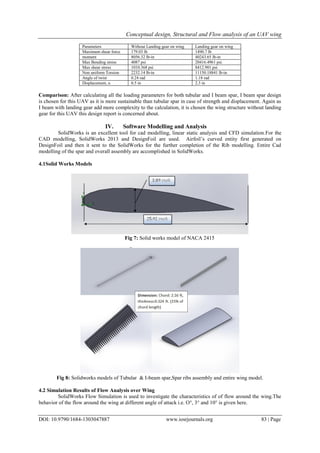
2.3 Aero foil Selection
Calculated Reynolds number = 58574.45 [12]
Previously from the design parameter section it is obtained that the thickness ratio approximately 15%
is desired as per the historical trend and NACA2415 has the same thickness ratio and the aero foil properties are
also obtained for from the respective Reynolds number of the expected operating condition.[17]
3. Conceptual design, Structural and Flow analysis of an UAV wing
DOI: 10.9790/1684-1303047887 www.iosrjournals.org 80 | Page
Fig 3: Co-efficient of drag [18]
AOA CD (3D)
0 0.0322
3 0.045
5 0.0569
10 0.0843
11 0.1
Table 3- CD at different AOA [18]
2.4 Performance parameter
At cruise condition the required coefficient of lift, CL=0.32 (calculated). Therefore, from the selected
aero foil, this required coefficient of lift can be produced at 30
angle of attack. Therefore, from the selected aero
foil, this required coefficient of lift can be produced at 30
angle of attack. From calculation, Ground distance
travelled during gliding, Rmax= 83083.18 ft.[3]
2.5 Control Surfaces and High Lift Devices Geometry
High lift devices are the aircraft components that are designed to increase lift. The devices may be a
fixed component or a movable mechanism which are deployed when required. Some common high lift devices
are flaps and slats.Aileron and flaps are conjoined with main wing. Ailerons and flaps geometry calculated
values are- [19]
Cruise 3
11Stall
4. Conceptual design, Structural and Flow analysis of an UAV wing
DOI: 10.9790/1684-1303047887 www.iosrjournals.org 81 | Page
Parameter Aileron Flap
Chord (considering Ca/Cw=0.2 , as the typical value) [11] 0.5 ft 0.2 ft [11]
Total Span 7.5 ft 6.75 ft
Length of each 3.75 ft 3ft
Area 1.62 ft2
0.6 ft2
Taper Ratio 1 1
III. Structural Analysis
Structural analysis is performed to evaluate whether a specific structural design will be able to
withstand external and internal forces and stresses.
3.1 Load Distribution on Wing
The net wing beam load distribution along the span is given by, q(y) = L (y) − N gm(y) [12]
By calculation, Net beam loading=23.87 lb/ft.
3.2 Structural Analysis on Tubular Spar
Analysis is done mainly two different design consideration. One is tubular spar with strut and another is tubular
spar without strut.
3.2.1 Tubular Spar without Strut
It is assumed the load is evenly distributed according to the wing chord. This is not quite true as the lift
falls off towards the wing tip and the lift loads are transferred to the main spar by the ribs, also the wing has
weight which will reduce the bending load.
Fig 4: Free Body Diagram (FBD) of Load distribution on wing[7]
Bending moment on wing spar=18127.08 lb-in.
3.2.2 Tubular Spar with Strut: The load is divided up into three sections, inner load, middle load and outer
load. The outer load includes the outer cantilevered section. The total calculation is shown for both tapered and
straight wing below. [7]
Fig 5: Tubular Spar with strut.
Parameters For Tapered wing (λ=0.4) For straight wing (λ=1)
Average wing loading 214.67 lb-ft 214.67 lb-ft
Root loading 178.9 lb-ft 143.11 lb-ft
Tip loading 71.6 lb-ft 143.11 lb-ft
5. Conceptual design, Structural and Flow analysis of an UAV wing
DOI: 10.9790/1684-1303047887 www.iosrjournals.org 82 | Page
Difference loading 107.3 lb-ft 0 [25]
Total Inner load 203.97 lb 214.665 lb
Total middle load 708.48 lb 644 lb
Outer load 901.52 lb 966 lb
Tensile load 901.52 lb 966 lb
Bending Moment 2364.72 lb-in 4722.6 lb-in
Max. Stress in spar 36471.1516 psi 72830 psi [20]
Comparison: So the maximum bending stress is higher for taper ratio 1 than the taper ratio 0.4.Though
in case of straight wing (λ=1) stress is higher but sometimes if the straight wing is enable to fulfill the design
requirement, then it is used instead of taper wing to avoid complexity.
3.2.3 Deflection in tubular spar
The net load produces shear and bending moment in the structure. The formulas of determining
deflection angle and deflection[23] are:
parameters For without strut For with strut
Deflection angle 4.8 rad 1.25 rad
Deflection 432 in 112.5 in
Comparison: So it is seen that the deflection is much higher in tubular spar without strut (432 in) than
the tubular spar with strut (112.5 in ). But in this case deflection with strut of tubular spar is also very much
high. But this can be reduced by changing or increasing the size of the tubular spar. But this will also add load
which is indeed a weight penalty for this design. That’s why for I beam the load, stress, displacement, torsion
again calculated and compared with tubular spar.
3.3 Structural Analysis on I - Beam
Structural analysis on spar consisting of I – Beam structure gives more strength then using a single circular
tube spar.
Fig 6: I- Beam
Two types of analysis is done for I - beam Aluminum alloy (6663-T6).
1) Without landing gear on wing
2) Landing gear on wing.
the calculated values for location of centroid, C1=1.94 in.
Moment of Inertia, Ixx=3.824 in4
& Iyy=0.142 in4
.From calculation,
6. Conceptual design, Structural and Flow analysis of an UAV wing
DOI: 10.9790/1684-1303047887 www.iosrjournals.org 83 | Page
Parameters Without Landing gear on wing Landing gear on wing
Maximum shear force 179.03 lb 1490.7 lb
moment 8056.32 lb-in 40243.65 lb-in
Max Bending stress 4087 psi 20416.4961 psi
Max shear stress 1010.368 psi 8412.901 psi
Non uniform Torsion 2232.14 lb-in 11150.18841 lb-in
Angle of twist 0.24 rad 1.18 rad
Displacement, u 0.5 in 2.3 in
Comparison: After calculating all the loading parameters for both tubular and I beam spar, I beam spar design
is chosen for this UAV as it is more sustainable than tubular spar in case of strength and displacement. Again as
I beam with landing gear add more complexity to the calculation, it is chosen the wing structure without landing
gear for this UAV this design report is concerned about.
IV. Software Modelling and Analysis
SolidWorks is an excellent tool for cad modelling, linear static analysis and CFD simulation.For the
CAD modelling, SolidWorks 2013 and DesignFoil are used. Airfoil’s curved entity first generated on
DesignFoil and then it sent to the SolidWorks for the further completion of the Rib modelling. Entire Cad
modelling of the spar and overall assembly are accomplished in SolidWorks.
4.1Solid Works Models
Fig 7: Solid works model of NACA 2415
Fig 8: Solidworks models of Tubular & I-beam spar,Spar ribs assembly and entire wing model.
4.2 Simulation Results of Flow Analysis over Wing
SolidWorks Flow Simulation is used to investigate the characteristics of of flow around the wing.The
behavior of the flow around the wing at different angle of attack i.e. O°, 3° and 10° is given here.
7. Conceptual design, Structural and Flow analysis of an UAV wing
DOI: 10.9790/1684-1303047887 www.iosrjournals.org 84 | Page
4.2.1 Velocity Distribution
Figure 9-1 Velocity distribution for 00
Figure 9-2 Velocity distribution for 30
Figure 9-3 Velocity distribution for 100
From the observation of flow characteristics for three different angles of attack we've seen that velocity
flow field diverges as the angle of attack increases.
4.2.2 Pressure Distribution: From the observation of the flow characteristics for three different angles of attack
we've observed that pressure distribution over the entire wing converges as the AOA increases.
Fig 10-1 Pressure distribution at 00
Fig 10-2 Pressure distribution at 30
8. Conceptual design, Structural and Flow analysis of an UAV wing
DOI: 10.9790/1684-1303047887 www.iosrjournals.org 85 | Page
Fig 10-3 Pressure distribution at 100
4.2.3 Temperature Distribution
Fig 11-1 Temperature distribution at 00
Fig 11-2 Temperature distribution at 30
Fig 11-3 Temperature distribution at 100
From the observation of the flow characteristics for three different angles of attack, we've observed that
the stagnation temperature region diverges as the angle of attack increases.
4.2.4 Vorticity Distribution: From the observation of flow characteristics for three different angles of attack
we've seen the strength of vortices increases as the angle of attack increases. However, increases in vortex lift
correspondingly increases high drag.
9. Conceptual design, Structural and Flow analysis of an UAV wing
DOI: 10.9790/1684-1303047887 www.iosrjournals.org 86 | Page
Fig12-1 Vorticity distribution at 00
Fig 12-2 Vorticity distribution at 30
Fig 12-3 Vorticity distribution at 100
V. Wing Construction
The flow chart for manufacturing the can be as following-
VI. Recommendations
The design of any kind of aircraft including UAV is mostly dependent on its purpose for which it is
going to be used or operated. All the performance parameters must be fulfilled for any design to be a successful
one. The following recommendations are put forward for the further advancement:
a) The present study on UAV wing has been worked on a simple surveillance type UAV, capable of carrying
moderate payloads for functional operation. That’s why the design point evaluations were commenced to
meet the overall maximum weight of the aircraft which needs to be lifted up to the maximum altitude and
the lift force that must be produced by the wing. The design focus could also have been upon various other
pivotal operating optimization criteria such as velocity, altitude, range, endurance, propulsive power etc.
b) The aerodynamics is solved for finding the design parameters and performance analysis based on the
traditional aerodynamic theories and historical trends. As the concepts and design ideas are being developed
day by day, more efficient design can be achieved by applying new innovative design and experimentation.
Some more features can be added to the wing structure like solar panels, blended wing body configuration
but these types of design require very advanced level of expertise.
10. Conceptual design, Structural and Flow analysis of an UAV wing
DOI: 10.9790/1684-1303047887 www.iosrjournals.org 87 | Page
c) For selecting the spar material, the calculations of structural analysis are done for only aluminum alloy and
the recommendation is done from this example considered. Some other materials also could have been
considered such as titanium alloy or some high strength light weight composites. In case of using
composites, better performance could be achieved though the cost will be very high.
d) Upon construction of a scaled wing structure, the static load testing could have been done by applying
weights and compared with the analytical and simulation results.
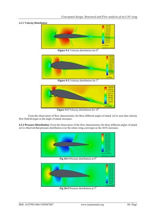
e) In this wing design process, the scaled models of the wing structure and structural components are modeled
using solid works software and static loadings and flow characteristics are analyzed through various
simulations presented in this report. The simulation results obtained have varied from analytical and
expected results in many cases shown here but the intention is to examine the design from both analytical
and simulation works. The simulation results have helped a lot for better understanding the design outcomes
and comparing the calculated and simulated findings. The deviations in the software simulations from the
analytical results might have occurred because of lack in expertise and accuracy in software modeling and
simulation works or some errors in defining ambient initial conditions. Computer configuration was also a
challenge to meet because it requires very high configuration computing devices to perform these
simulations more efficiently which is not affordable at this time.
VII. Conclusion
This project report represents a conceptual design approach of a medium weight surveillance type
UAV wing in a chronological order including the structural linear static analysis to defy the undecidability of
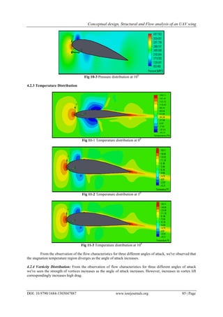
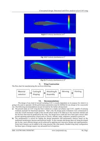
the CAD model of the proposed UAV wing. Software aided flow analysis is also implemented to understand the
behavior of the flow over the wing surface including velocity distribution, temperature distribution, pressure
distribution, vorticity distribution etc. Substantial steps of construction are also proposed in this report. Through
this report, an attempt has been made to understand an idea about the design approach of an aircraft wing
through the study on an UAV wing. The standout point of this paper is that it attempts to conduct a dedicated
study on overall aspect and illustrates details about the concepts of the UAV wing.
References
[1]. Reg austin, UAVS Design, Development and Deployment, P-34, , Introduction to UAS
[2]. Daniel P. Raymer , “Aircraft design: A conceptual approach”, Thickness Ratio historical trend , Fig 4.14, Fourth Edition, Pg 51,
2006
[3]. John D. Anderson Jr, “Aircraft Performance and Design”, Tata McGraw-Hill Edition 2010.
[4]. Mohammad Sadrey, “Chapter 5 Wing Design”, July 27, 2013
[5]. Ajoy Kumar Kundu, “Aircraft design”, 2010
[6]. Ajoy Kumar Kundu, “Aircraft design”, Wing design, fig. 5.1, Pg 169, 2010
[7]. Available at http://www.propdesigner.co.uk/html/load_on_wing.html
[8]. Wing Bending Calculations, MIT open course, Lab 10 Lecture Notes
[9]. www.nptel.ac.in/courses/Webcourse-contents/IIT-
[10]. Barnard Microsystems website, UAV design guidelines.
[11]. Ajoy Kumar Kundu, “Aircraft design” , Aerodynamic Considerations, Table 3.1, Pg 86, 2010
[12]. John D. Anderson Jr, “Aircraft Performance and Design”, Tata McGraw-Hill Edition 2010.
[13]. Google image
[14]. Daniel P. Raymer,Aircraft design: A conceptual Approach,Wing sweep historical trend, fig. 4.20, Pg 57, 2010
[15]. Daniel P. Raymer , “Aircraft design: A conceptual approach”, Wing tips, Fig. 4.29, Fourth Edition, Pg 70, 2006
[16]. Mohammad Sadrey, “Chapter 5 Wing Design”, Airfoil geometric parameters, Fig. 5.5, Pg 180, July 27, 2013
[17]. www.airfoildb.com
[18]. Available at http://airfoiltools.com/airfoil/details?airfoil=n2415-il
[19]. Daniel P.Raymer, “Aircraft design: A conceptual approach”, Aileron guideline, fig. 6.3, Fourth Edition, Pg 124, 2006
[20]. www.engineeringtoolbox.com/young-modulus-d_417.html, “Aluminum Alloys”
[21]. www.sketchup.engineeringtoolbox.com/aluminum-seamless-extruded-pipes-tubes
[22]. http://en.wikipedia.org/wiki/Buckling
[23]. Institute for steel development & growth,teaching materials – contents, no 17, beams subjected to torsion and bending
[24]. http://en.wikipedia.org/wiki/Load_factor
[25]. Daniel P. Raymer, “Aircraft design: A conceptual approach”, Chapter 4, Fourth Edition, 2006