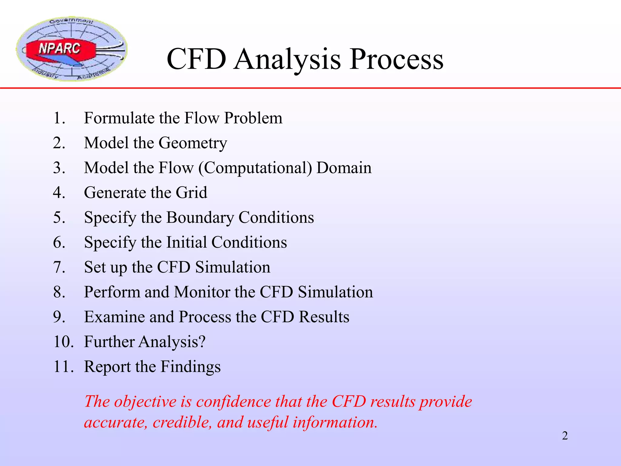
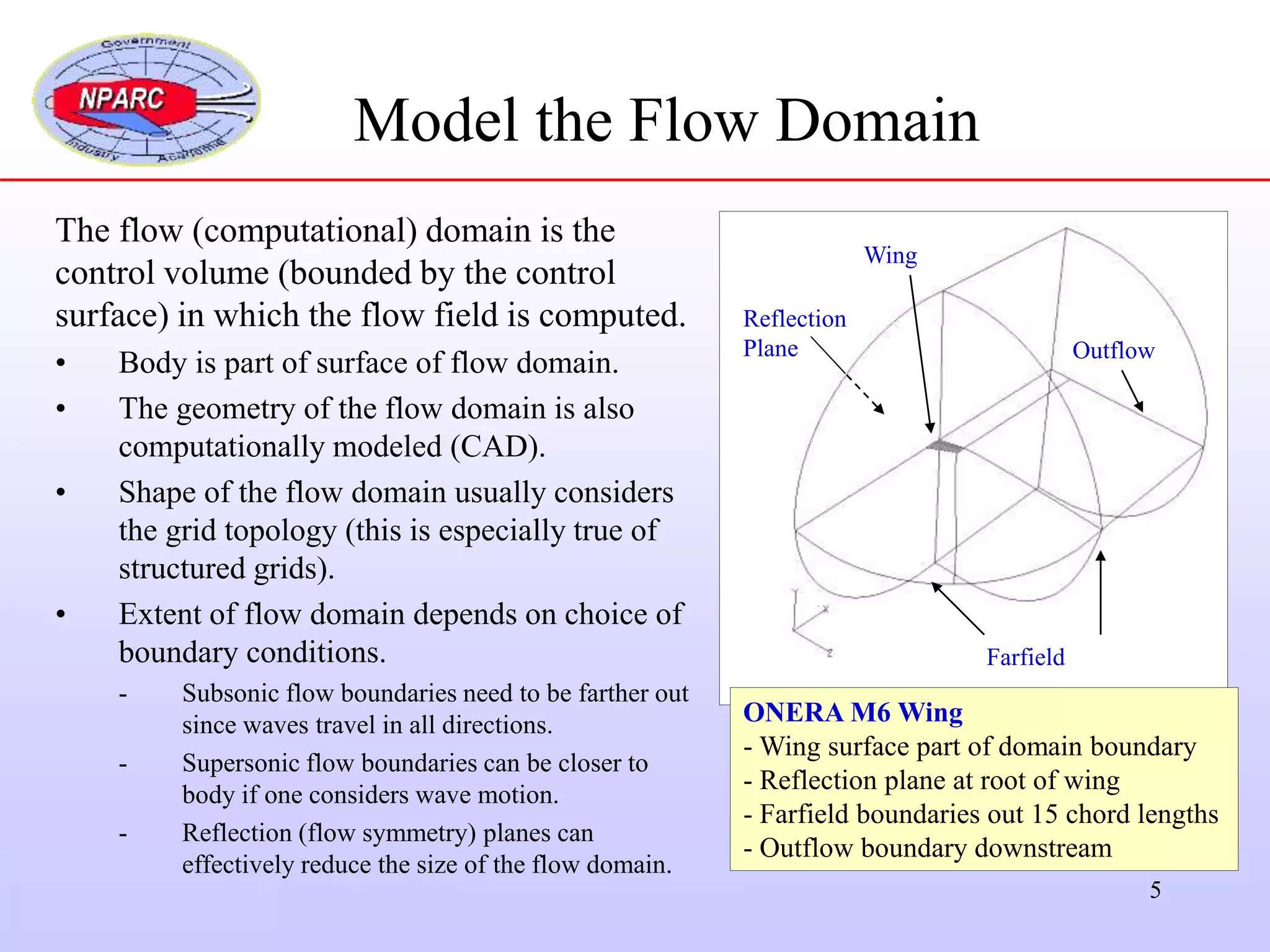
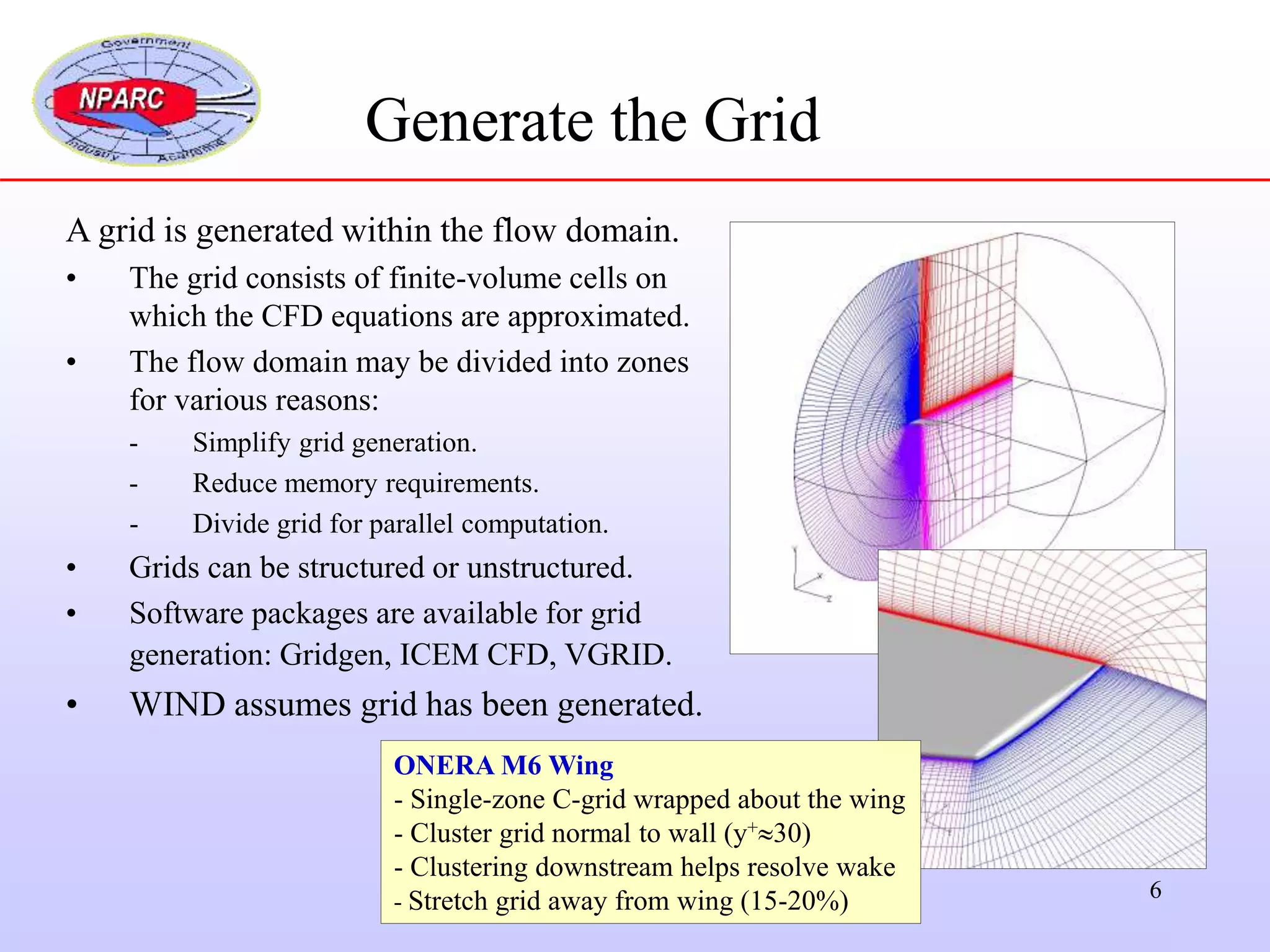
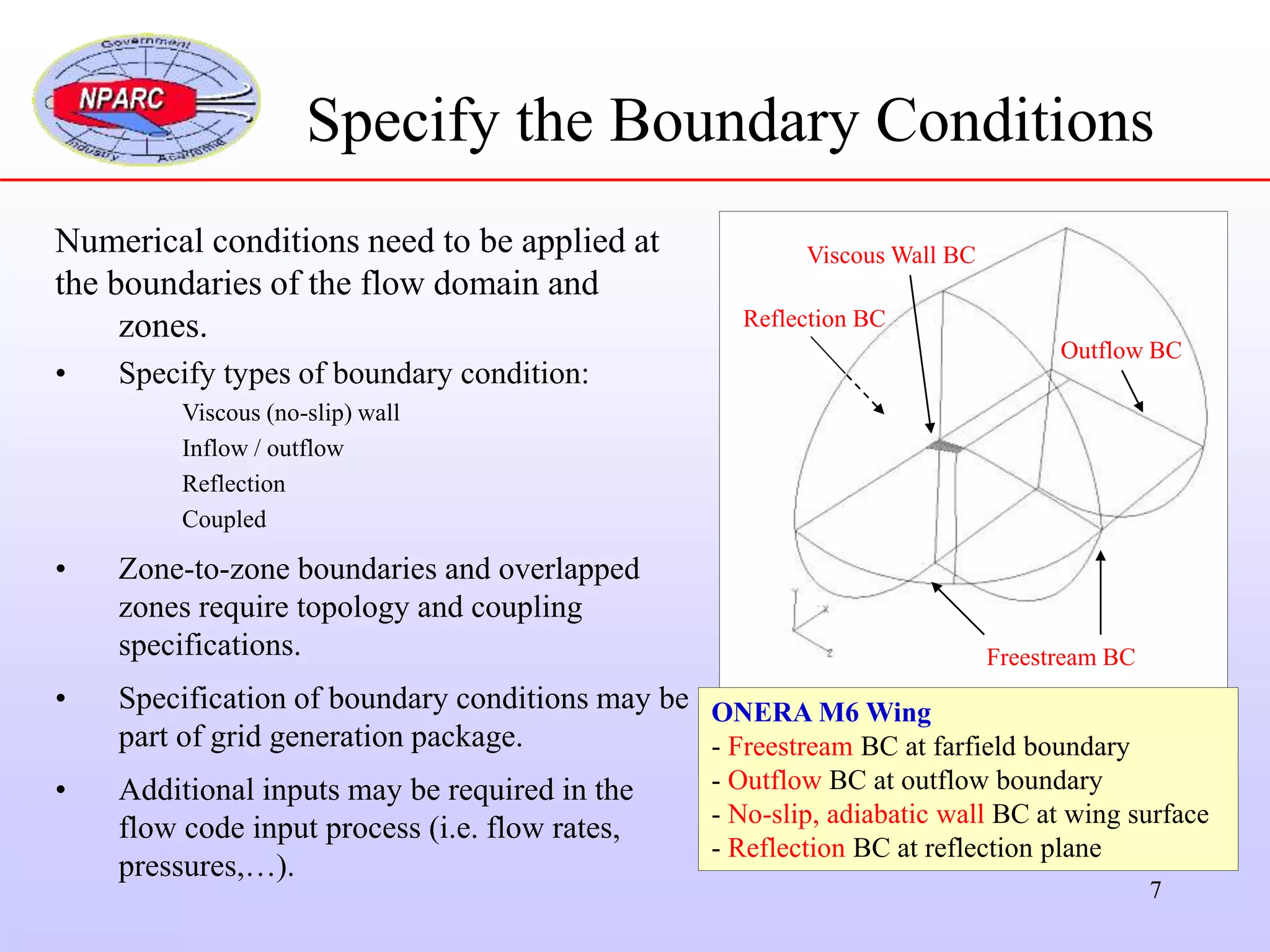
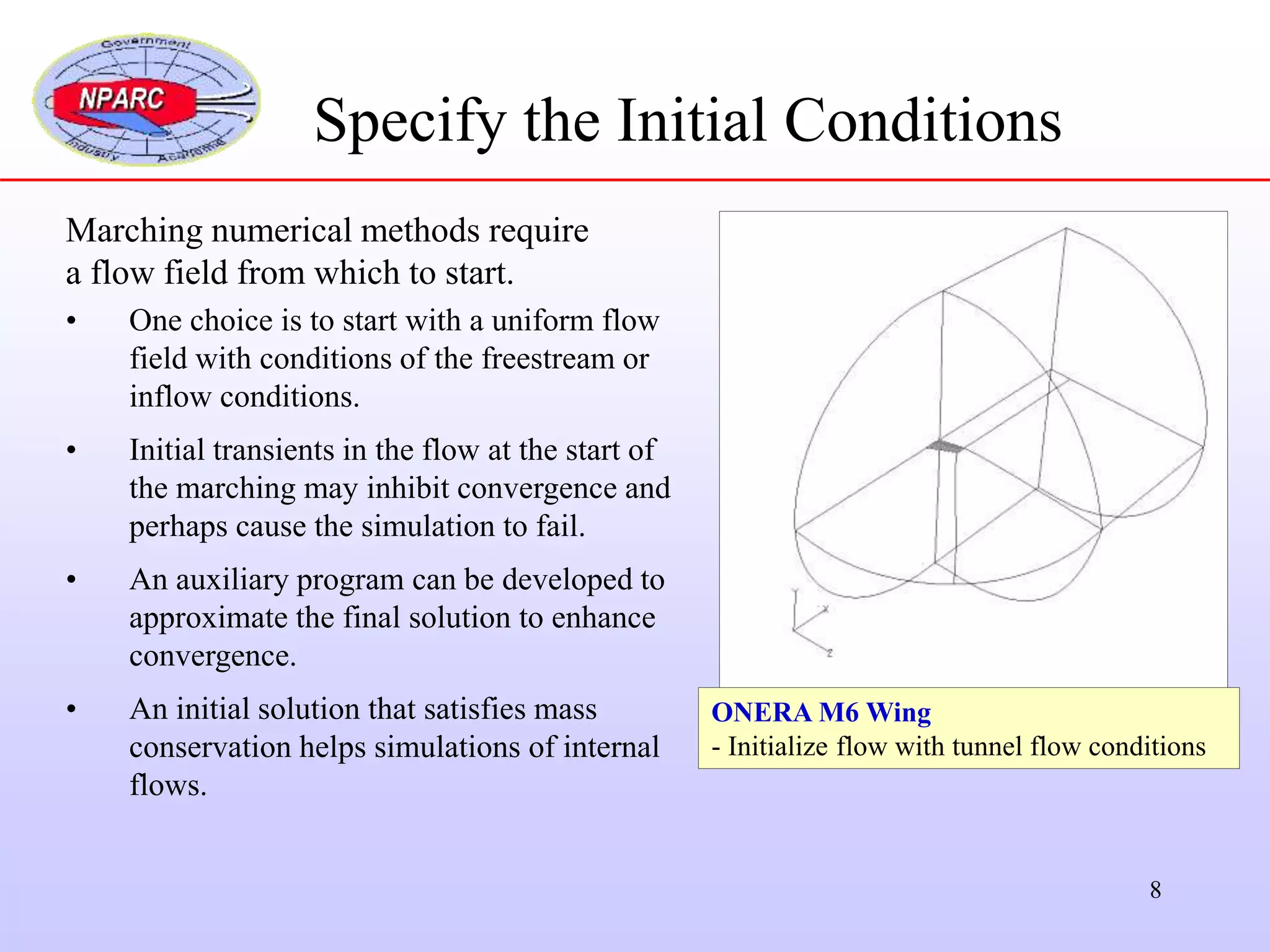
SlideShare a Scribd company logo
1
CFD Analysis Process
2
CFD Analysis Process
1. Formulate the Flow Problem
2. Model the Geometry
3. Model the Flow (Computational) Domain
4. Generate the Grid
5. Specify the Boundary Conditions
6. Specify the Initial Conditions
7. Set up the CFD Simulation
8. Perform and Monitor the CFD Simulation
9. Examine and Process the CFD Results
10. Further Analysis?
11. Report the Findings
The objective is confidence that the CFD results provide
accurate, credible, and useful information.
3
Formulate the Flow Problem
Determine the following:
1. What is the objective?
Engineering quantities
Performance
Proof of concept
2. What is known?
Freestream conditions
Geometry
Configuration
3. What is best analysis approach?
Steady or unsteady flow?
Are viscous forces important?
Are shocks present?
What equations to solve?
What other flow models are needed?
ONERA M6 Wing
- Section coordinates and wing tip shape
- Tunnel test section: M, Re, Tt
- Wing: 
- Aerodynamics quantities to determine:
Static pressure distributions (loading)
Lift and drag coefficients
4
Model the Geometry
ONERA M6 Wing
- Table of airfoil coordinates
- Drawing of planform shape
- Develop a CAD model of wing
Determine the following:
1. What geometric features are significant?
Steps, leading edges, trailing edges
2. Any simplification of the geometry needed?
Smooth over small steps
3. What computational format for geometry?
Lines, curves, surfaces
CAD file format (IGES, Step, …)
5
Model the Flow Domain
The flow (computational) domain is the
control volume (bounded by the control
surface) in which the flow field is computed.
• Body is part of surface of flow domain.
• The geometry of the flow domain is also
computationally modeled (CAD).
• Shape of the flow domain usually considers
the grid topology (this is especially true of
structured grids).
• Extent of flow domain depends on choice of
boundary conditions.
- Subsonic flow boundaries need to be farther out
since waves travel in all directions.
- Supersonic flow boundaries can be closer to
body if one considers wave motion.
- Reflection (flow symmetry) planes can
effectively reduce the size of the flow domain.
Reflection
Plane
Farfield
Wing
Outflow
ONERA M6 Wing
- Wing surface part of domain boundary
- Reflection plane at root of wing
- Farfield boundaries out 15 chord lengths
- Outflow boundary downstream
6
Generate the Grid
A grid is generated within the flow domain.
• The grid consists of finite-volume cells on
which the CFD equations are approximated.
• The flow domain may be divided into zones
for various reasons:
- Simplify grid generation.
- Reduce memory requirements.
- Divide grid for parallel computation.
• Grids can be structured or unstructured.
• Software packages are available for grid
generation: Gridgen, ICEM CFD, VGRID.
• WIND assumes grid has been generated.
ONERA M6 Wing
- Single-zone C-grid wrapped about the wing
- Cluster grid normal to wall (y+30)
- Clustering downstream helps resolve wake
- Stretch grid away from wing (15-20%)
7
Specify the Boundary Conditions
Numerical conditions need to be applied at
the boundaries of the flow domain and
zones.
• Specify types of boundary condition:
Viscous (no-slip) wall
Inflow / outflow
Reflection
Coupled
• Zone-to-zone boundaries and overlapped
zones require topology and coupling
specifications.
• Specification of boundary conditions may be
part of grid generation package.
• Additional inputs may be required in the
flow code input process (i.e. flow rates,
pressures,…).
Reflection BC
Freestream BC
Viscous Wall BC
Outflow BC
ONERA M6 Wing
- Freestream BC at farfield boundary
- Outflow BC at outflow boundary
- No-slip, adiabatic wall BC at wing surface
- Reflection BC at reflection plane
8
Specify the Initial Conditions
Marching numerical methods require
a flow field from which to start.
• One choice is to start with a uniform flow
field with conditions of the freestream or
inflow conditions.
• Initial transients in the flow at the start of
the marching may inhibit convergence and
perhaps cause the simulation to fail.
• An auxiliary program can be developed to
approximate the final solution to enhance
convergence.
• An initial solution that satisfies mass
conservation helps simulations of internal
flows.
ONERA M6 Wing
- Initialize flow with tunnel flow conditions
9
The simulation requires several input files:
Grid file
Initial solution file
Input data file
Auxiliary files (i.e. multi-processor, local boundary
conditions, chemistry,…)
Input Data File
Reference state
Freestream flow conditions (Mach, p, T, Re)
Configuration (angle-of-attack & sideslip)
Physical model inputs
Dimensionality (3D, 2D, axisymmetric)
Flow equations (RANS, PNS, Euler)
Turbulence model
Gas model / chemistry
Set Up the CFD Simulation
ONERA M6 Wing
Common Grid File (m6wing.cgd)
Common Solution File (m6wing.cfl)
Input Data File (m6wing.dat)
Multi-Processor Control File (m6wing.mpc)
Numerical algorithm inputs
Time-marching / space-marching
Explicit / implicit operators
Damping schemes
Convergence acceleration
Convergence monitoring
10
Perform and Monitor the CFD Simulation
• Simulations typically require CPU
times on the order of hours and days.
• Marching methods are monitored to
determine iterative convergence.
• Residuals of conservation equations
should approach zero as the number of
iterations increases.
• Satisfaction of conservation statements
(mass, momentum, energy, …) are also
useful for monitoring iterative
convergence.
• Convergence to design / performance
quantity (lift, drag, recovery) is often a
critical test for iterative convergence.
ONERA M6 Wing
Monitored the residuals, as well as, the
lift and drag on the wing with number of
iterations.
Lift on the M6 wing
11
Examine and Process the CFD Results
Visualization:
• View flow properties (Mach, pressure, vectors) to get
overall view of flow (CFD: Colorful Fluid Dynamics).
• Various packages: FAST, Fieldview, Ensight, TecPlot,
CFPOST.
Static pressures on the M6 wing
Solution Processing:
• Extract data (lift, drag, recovery, spillage, etc…) useful
for iterative convergence monitoring and engineering
design (CFPOST).
12
Further Analysis?
Once a simulation has reached iterative convergence and the results examined
and processed, there may be various reasons to make changes and continue
with another simulation:
• Change of physical model parameters to examine sensitivity.
Turbulence model / parameters
Gas / chemistry model
• Change of numerical algorithm parameters to examine sensitivity.
Implicit or explicit method
Time step parameters
Numerical flux parameters
• Change or refine the grid to examine grid sensitivity.
• Change the geometry as part of design parametric study.
• Change initial solution to examine iterative convergence.
13
Report the Findings
CFD results, like any other data, should be reported along with some idea of
the level of error that it contains and indications of how much confidence
one has in the data.
• What are engineering results and uncertainty of those results?
• How much error is there in the iterative convergence?
• How much error is there in the grid convergence?
• How sensitive are the results to model parameters (turbulence, etc…)
• How sensitive are the results to algorithm parameters (CFL, etc…)
• How do the results compare to similar experimental or theoretical data?
• Statistical analysis may be useful for reporting such information.
Next 

More Related Content

Similar to CFDProcess (1).ppt

Similar to CFDProcess (1).ppt (20)

CFD Best Practices and Troubleshooting - with speaker notes
CFD Best Practices and Troubleshooting - with speaker notesCFD Best Practices and Troubleshooting - with speaker notes
CFD Best Practices and Troubleshooting - with speaker notes
 
Fluent and Gambit Workshop
Fluent and Gambit WorkshopFluent and Gambit Workshop
Fluent and Gambit Workshop
 
FLUID MECHANICS - COMPUTATIONAL FLUID DYNAMICS (CFD)
FLUID MECHANICS - COMPUTATIONAL FLUID DYNAMICS (CFD)FLUID MECHANICS - COMPUTATIONAL FLUID DYNAMICS (CFD)
FLUID MECHANICS - COMPUTATIONAL FLUID DYNAMICS (CFD)
 
Use of cfd in aerodynamic performance of race car
Use of cfd in aerodynamic performance of race carUse of cfd in aerodynamic performance of race car
Use of cfd in aerodynamic performance of race car
 
Cfd 0
Cfd 0Cfd 0
Cfd 0
 
Computational Estimation of Flow through the C-D Supersonic Nozzle and Impuls...
Computational Estimation of Flow through the C-D Supersonic Nozzle and Impuls...Computational Estimation of Flow through the C-D Supersonic Nozzle and Impuls...
Computational Estimation of Flow through the C-D Supersonic Nozzle and Impuls...
 
Onera M6 Wing CFD.pptx
Onera M6 Wing CFD.pptxOnera M6 Wing CFD.pptx
Onera M6 Wing CFD.pptx
 
Cfd 0
Cfd 0Cfd 0
Cfd 0
 
11 generalsisation of fluent
11 generalsisation of fluent11 generalsisation of fluent
11 generalsisation of fluent
 
CFD Introduction using Ansys Fluent
CFD Introduction using Ansys FluentCFD Introduction using Ansys Fluent
CFD Introduction using Ansys Fluent
 
Flow Modification over Rotor Blade with Suction Boundary Layer Control Technique
Flow Modification over Rotor Blade with Suction Boundary Layer Control TechniqueFlow Modification over Rotor Blade with Suction Boundary Layer Control Technique
Flow Modification over Rotor Blade with Suction Boundary Layer Control Technique
 
Lecture 1.ppt
Lecture 1.pptLecture 1.ppt
Lecture 1.ppt
 
Elements CAE white paper
Elements CAE white paperElements CAE white paper
Elements CAE white paper
 
CFD_Lecture_(Introduction_to_CFD).ppt
CFD_Lecture_(Introduction_to_CFD).pptCFD_Lecture_(Introduction_to_CFD).ppt
CFD_Lecture_(Introduction_to_CFD).ppt
 
Determination of shock losses and pressure losses in ug mine openings (1)
Determination of shock losses and pressure losses in ug mine openings (1)Determination of shock losses and pressure losses in ug mine openings (1)
Determination of shock losses and pressure losses in ug mine openings (1)
 
Determination of shock losses and pressure losses in ug mine openings
Determination of shock losses and pressure losses in ug mine openingsDetermination of shock losses and pressure losses in ug mine openings
Determination of shock losses and pressure losses in ug mine openings
 
Aircraft Design
Aircraft DesignAircraft Design
Aircraft Design
 
4 lockheed
4 lockheed4 lockheed
4 lockheed
 
Introduction to Computational Fluid Dynamics (CFD)
Introduction to Computational Fluid Dynamics (CFD)Introduction to Computational Fluid Dynamics (CFD)
Introduction to Computational Fluid Dynamics (CFD)
 
Lecture 1 velmurugan
Lecture 1 velmuruganLecture 1 velmurugan
Lecture 1 velmurugan
 

Recently uploaded

The Future of Autonomous Vehicles | civilthings.com | Detailed information
The Future of Autonomous Vehicles | civilthings.com |  Detailed informationThe Future of Autonomous Vehicles | civilthings.com |  Detailed information
The Future of Autonomous Vehicles | civilthings.com | Detailed information
gettygaming1
 
一比一原版SDSU毕业证圣地亚哥州立大学毕业证成绩单如何办理
一比一原版SDSU毕业证圣地亚哥州立大学毕业证成绩单如何办理一比一原版SDSU毕业证圣地亚哥州立大学毕业证成绩单如何办理
一比一原版SDSU毕业证圣地亚哥州立大学毕业证成绩单如何办理
psavhef
 
一比一原版BC毕业证波士顿学院毕业证成绩单如何办理
一比一原版BC毕业证波士顿学院毕业证成绩单如何办理一比一原版BC毕业证波士顿学院毕业证成绩单如何办理
一比一原版BC毕业证波士顿学院毕业证成绩单如何办理
amvovau
 

Recently uploaded (8)

The Future of Autonomous Vehicles | civilthings.com | Detailed information
The Future of Autonomous Vehicles | civilthings.com |  Detailed informationThe Future of Autonomous Vehicles | civilthings.com |  Detailed information
The Future of Autonomous Vehicles | civilthings.com | Detailed information
 
Essential Maintenance Tips For Commercial Vans.
Essential Maintenance Tips For Commercial Vans.Essential Maintenance Tips For Commercial Vans.
Essential Maintenance Tips For Commercial Vans.
 
Understanding BDA and BBMP: Key Players in Bangalore’s Urban Development
Understanding BDA and BBMP: Key Players in Bangalore’s Urban DevelopmentUnderstanding BDA and BBMP: Key Players in Bangalore’s Urban Development
Understanding BDA and BBMP: Key Players in Bangalore’s Urban Development
 
一比一原版SDSU毕业证圣地亚哥州立大学毕业证成绩单如何办理
一比一原版SDSU毕业证圣地亚哥州立大学毕业证成绩单如何办理一比一原版SDSU毕业证圣地亚哥州立大学毕业证成绩单如何办理
一比一原版SDSU毕业证圣地亚哥州立大学毕业证成绩单如何办理
 
gtyccccccccccccccccccccccccccccccccccccccccccccccccccccccc
gtycccccccccccccccccccccccccccccccccccccccccccccccccccccccgtyccccccccccccccccccccccccccccccccccccccccccccccccccccccc
gtyccccccccccccccccccccccccccccccccccccccccccccccccccccccc
 
Core technology of Hyundai Motor Group's EV platform 'E-GMP'
Core technology of Hyundai Motor Group's EV platform 'E-GMP'Core technology of Hyundai Motor Group's EV platform 'E-GMP'
Core technology of Hyundai Motor Group's EV platform 'E-GMP'
 
一比一原版BC毕业证波士顿学院毕业证成绩单如何办理
一比一原版BC毕业证波士顿学院毕业证成绩单如何办理一比一原版BC毕业证波士顿学院毕业证成绩单如何办理
一比一原版BC毕业证波士顿学院毕业证成绩单如何办理
 
Advanced Technology for Auto Part Industry Inventory Solutions
Advanced Technology for Auto Part Industry Inventory SolutionsAdvanced Technology for Auto Part Industry Inventory Solutions
Advanced Technology for Auto Part Industry Inventory Solutions
 

CFDProcess (1).ppt

  • 2. 2 CFD Analysis Process 1. Formulate the Flow Problem 2. Model the Geometry 3. Model the Flow (Computational) Domain 4. Generate the Grid 5. Specify the Boundary Conditions 6. Specify the Initial Conditions 7. Set up the CFD Simulation 8. Perform and Monitor the CFD Simulation 9. Examine and Process the CFD Results 10. Further Analysis? 11. Report the Findings The objective is confidence that the CFD results provide accurate, credible, and useful information.
  • 3. 3 Formulate the Flow Problem Determine the following: 1. What is the objective? Engineering quantities Performance Proof of concept 2. What is known? Freestream conditions Geometry Configuration 3. What is best analysis approach? Steady or unsteady flow? Are viscous forces important? Are shocks present? What equations to solve? What other flow models are needed? ONERA M6 Wing - Section coordinates and wing tip shape - Tunnel test section: M, Re, Tt - Wing:  - Aerodynamics quantities to determine: Static pressure distributions (loading) Lift and drag coefficients
  • 4. 4 Model the Geometry ONERA M6 Wing - Table of airfoil coordinates - Drawing of planform shape - Develop a CAD model of wing Determine the following: 1. What geometric features are significant? Steps, leading edges, trailing edges 2. Any simplification of the geometry needed? Smooth over small steps 3. What computational format for geometry? Lines, curves, surfaces CAD file format (IGES, Step, …)
  • 5. 5 Model the Flow Domain The flow (computational) domain is the control volume (bounded by the control surface) in which the flow field is computed. • Body is part of surface of flow domain. • The geometry of the flow domain is also computationally modeled (CAD). • Shape of the flow domain usually considers the grid topology (this is especially true of structured grids). • Extent of flow domain depends on choice of boundary conditions. - Subsonic flow boundaries need to be farther out since waves travel in all directions. - Supersonic flow boundaries can be closer to body if one considers wave motion. - Reflection (flow symmetry) planes can effectively reduce the size of the flow domain. Reflection Plane Farfield Wing Outflow ONERA M6 Wing - Wing surface part of domain boundary - Reflection plane at root of wing - Farfield boundaries out 15 chord lengths - Outflow boundary downstream
  • 6. 6 Generate the Grid A grid is generated within the flow domain. • The grid consists of finite-volume cells on which the CFD equations are approximated. • The flow domain may be divided into zones for various reasons: - Simplify grid generation. - Reduce memory requirements. - Divide grid for parallel computation. • Grids can be structured or unstructured. • Software packages are available for grid generation: Gridgen, ICEM CFD, VGRID. • WIND assumes grid has been generated. ONERA M6 Wing - Single-zone C-grid wrapped about the wing - Cluster grid normal to wall (y+30) - Clustering downstream helps resolve wake - Stretch grid away from wing (15-20%)
  • 7. 7 Specify the Boundary Conditions Numerical conditions need to be applied at the boundaries of the flow domain and zones. • Specify types of boundary condition: Viscous (no-slip) wall Inflow / outflow Reflection Coupled • Zone-to-zone boundaries and overlapped zones require topology and coupling specifications. • Specification of boundary conditions may be part of grid generation package. • Additional inputs may be required in the flow code input process (i.e. flow rates, pressures,…). Reflection BC Freestream BC Viscous Wall BC Outflow BC ONERA M6 Wing - Freestream BC at farfield boundary - Outflow BC at outflow boundary - No-slip, adiabatic wall BC at wing surface - Reflection BC at reflection plane
  • 8. 8 Specify the Initial Conditions Marching numerical methods require a flow field from which to start. • One choice is to start with a uniform flow field with conditions of the freestream or inflow conditions. • Initial transients in the flow at the start of the marching may inhibit convergence and perhaps cause the simulation to fail. • An auxiliary program can be developed to approximate the final solution to enhance convergence. • An initial solution that satisfies mass conservation helps simulations of internal flows. ONERA M6 Wing - Initialize flow with tunnel flow conditions
  • 9. 9 The simulation requires several input files: Grid file Initial solution file Input data file Auxiliary files (i.e. multi-processor, local boundary conditions, chemistry,…) Input Data File Reference state Freestream flow conditions (Mach, p, T, Re) Configuration (angle-of-attack & sideslip) Physical model inputs Dimensionality (3D, 2D, axisymmetric) Flow equations (RANS, PNS, Euler) Turbulence model Gas model / chemistry Set Up the CFD Simulation ONERA M6 Wing Common Grid File (m6wing.cgd) Common Solution File (m6wing.cfl) Input Data File (m6wing.dat) Multi-Processor Control File (m6wing.mpc) Numerical algorithm inputs Time-marching / space-marching Explicit / implicit operators Damping schemes Convergence acceleration Convergence monitoring
  • 10. 10 Perform and Monitor the CFD Simulation • Simulations typically require CPU times on the order of hours and days. • Marching methods are monitored to determine iterative convergence. • Residuals of conservation equations should approach zero as the number of iterations increases. • Satisfaction of conservation statements (mass, momentum, energy, …) are also useful for monitoring iterative convergence. • Convergence to design / performance quantity (lift, drag, recovery) is often a critical test for iterative convergence. ONERA M6 Wing Monitored the residuals, as well as, the lift and drag on the wing with number of iterations. Lift on the M6 wing
  • 11. 11 Examine and Process the CFD Results Visualization: • View flow properties (Mach, pressure, vectors) to get overall view of flow (CFD: Colorful Fluid Dynamics). • Various packages: FAST, Fieldview, Ensight, TecPlot, CFPOST. Static pressures on the M6 wing Solution Processing: • Extract data (lift, drag, recovery, spillage, etc…) useful for iterative convergence monitoring and engineering design (CFPOST).
  • 12. 12 Further Analysis? Once a simulation has reached iterative convergence and the results examined and processed, there may be various reasons to make changes and continue with another simulation: • Change of physical model parameters to examine sensitivity. Turbulence model / parameters Gas / chemistry model • Change of numerical algorithm parameters to examine sensitivity. Implicit or explicit method Time step parameters Numerical flux parameters • Change or refine the grid to examine grid sensitivity. • Change the geometry as part of design parametric study. • Change initial solution to examine iterative convergence.
  • 13. 13 Report the Findings CFD results, like any other data, should be reported along with some idea of the level of error that it contains and indications of how much confidence one has in the data. • What are engineering results and uncertainty of those results? • How much error is there in the iterative convergence? • How much error is there in the grid convergence? • How sensitive are the results to model parameters (turbulence, etc…) • How sensitive are the results to algorithm parameters (CFL, etc…) • How do the results compare to similar experimental or theoretical data? • Statistical analysis may be useful for reporting such information. Next 