Download to read offline

![CCNPv7 ROUTE Lab 2-1, EIGRP Load Balancing
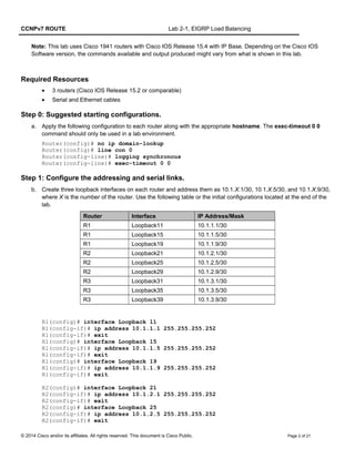
IP routing debugging is on
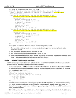
R3# debug ip eigrp 100
R3# conf t
Enter configuration commands, one per line. End with CNTL/Z.
R3(config)# router eigrp 100
*Jun 22 11:06:09.315: RT: add router 2048, all protocols have local database
R3(config-router)# network 10.0.0.0
*Jun 22 11:06:18.591: %DUAL-5-NBRCHANGE: EIGRP-IPv4 100: Neighbor 10.1.103.1
(Serial0/0/0) is up: new adjacency
*Jun 22 11:06:18.591: %DUAL-5-NBRCHANGE: EIGRP-IPv4 100: Neighbor 10.1.203.2
(Serial0/0/1) is up: new adjacency
*Jun 22 11:06:19.055: RT: updating eigrp 10.1.102.0/29 (0x0) :
via 10.1.103.1 Se0/0/0 0 1048578
*Jun 22 11:06:19.055: RT: add 10.1.102.0/29 via 10.1.103.1, eigrp metric
[90/41024000]
*Jun 22 11:06:19.055: RT: updating eigrp 10.1.1.0/30 (0x0) :
via 10.1.103.1 Se0/0/0
R3(config-router)#end 0 1048578
*Jun 22 11:06:19.055: RT: add 10.1.1.0/30 via 10.1.103.1, eigrp metric [90/40640000]
*Jun 22 11:06:19.055: RT: updating eigrp 10.1.1.4/30 (0x0) :
via 10.1.103.1 Se0/0/0 0 1048578
*Jun 22 11:06:19.055: RT: add 10.1.1.4/30 via 10.1.103.1, eigrp metric [90/40640000]
*Jun 22 11:06:19.055: RT: updating eigrp 10.1.1.8/30 (0x0) :
via 10.1.103.1 Se0/0/0 0 1048578
*Jun 22 11:06:19.055: RT: add 10.1.1.8/30 via 10.1.103.1, eigrp metric [90/40640000]
*Jun 22 11:06:19.059: RT: updating eigrp 10.1.2.0/30 (0x0) :
via 10.1.103.1 Se0/0/0 0 1048578
*Jun 22 11:06:19.059: RT: add 10.1.2.0/30 via 10.1.103.1, eigrp metric [90/41152000]
*Jun 22 11:06:19.059: RT: updating eigrp 10.1.2.4/30 (0x0) :
via 10.1.103.1 Se0/0/0 0 1048578
<output omitted>
R3#
R3(config-router)# end
R3#
R3#undebug all
All possible debugging has been turned off
R3#
Essentially, the EIGRP DUAL state machine has just computed the topology table for these routes and installed
them in the routing table.
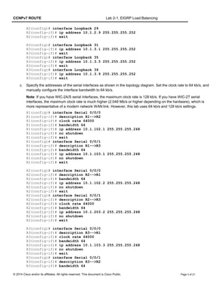
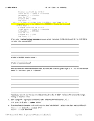
c. Check to see that these routes exist in the routing table with the show ip route command.
R3# show ip route
Codes: L - local, C - connected, S - static, R - RIP, M - mobile, B - BGP
D - EIGRP, EX - EIGRP external, O - OSPF, IA - OSPF inter area
N1 - OSPF NSSA external type 1, N2 - OSPF NSSA external type 2
E1 - OSPF external type 1, E2 - OSPF external type 2
i - IS-IS, su - IS-IS summary, L1 - IS-IS level-1, L2 - IS-IS level-2
ia - IS-IS inter area, * - candidate default, U - per-user static route
o - ODR, P - periodic downloaded static route, H - NHRP, l - LISP
© 2014 Cisco and/or its affiliates. All rights reserved. This document is Cisco Public. Page 5 of 21](https://image.slidesharecdn.com/ccnpv7routelab2-1eigrp-load-balancingstudent-160718181051/85/Ccn-pv7-route_lab2-1_eigrp-load-balancing_student-5-320.jpg)
![CCNPv7 ROUTE Lab 2-1, EIGRP Load Balancing
a - application route
+ - replicated route, % - next hop override
Gateway of last resort is not set
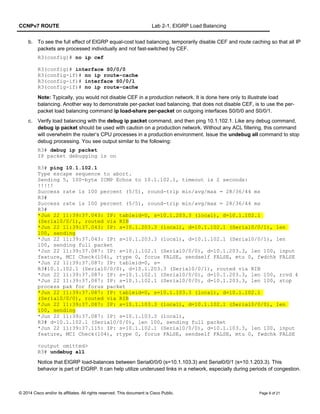
10.0.0.0/8 is variably subnetted, 17 subnets, 3 masks
D 10.1.1.0/30 [90/40640000] via 10.1.103.1, 00:10:54, Serial0/0/0
D 10.1.1.4/30 [90/40640000] via 10.1.103.1, 00:10:54, Serial0/0/0
D 10.1.1.8/30 [90/40640000] via 10.1.103.1, 00:10:54, Serial0/0/0
D 10.1.2.0/30 [90/40640000] via 10.1.203.2, 00:10:54, Serial0/0/1
D 10.1.2.4/30 [90/40640000] via 10.1.203.2, 00:10:54, Serial0/0/1
D 10.1.2.8/30 [90/40640000] via 10.1.203.2, 00:10:54, Serial0/0/1
C 10.1.3.0/30 is directly connected, Loopback31
L 10.1.3.1/32 is directly connected, Loopback31
C 10.1.3.4/30 is directly connected, Loopback35
L 10.1.3.5/32 is directly connected, Loopback35
C 10.1.3.8/30 is directly connected, Loopback39
L 10.1.3.9/32 is directly connected, Loopback39
D 10.1.102.0/29 [90/41024000] via 10.1.203.2, 00:10:54, Serial0/0/1
[90/41024000] via 10.1.103.1, 00:10:54, Serial0/0/0
C 10.1.103.0/29 is directly connected, Serial0/0/0
L 10.1.103.3/32 is directly connected, Serial0/0/0
C 10.1.203.0/29 is directly connected, Serial0/0/1
L 10.1.203.3/32 is directly connected, Serial0/0/1
R3#
d. After you have full adjacency between the routers, ping all the remote loopbacks to ensure full connectivity.
You should receive ICMP echo replies for each address pinged.
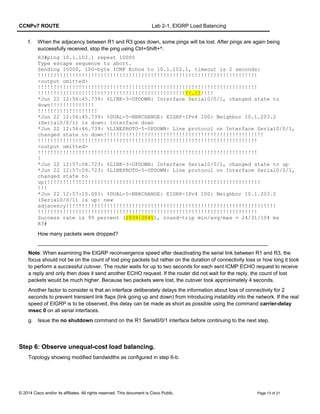
e. Verify the EIGRP neighbor relationships with the show ip eigrp neighbors command.
R1# show ip eigrp neighbors
EIGRP-IPv4 Neighbors for AS(100)
H Address Interface Hold Uptime SRTT RTO Q Seq
(sec) (ms) Cnt Num
1 10.1.103.3 Se0/0/1 13 00:14:20 49 2340 0 6
0 10.1.102.2 Se0/0/0 10 00:29:14 37 2340 0 36
R1#
R2# show ip eigrp neighbors
EIGRP-IPv4 Neighbors for AS(100)
H Address Interface Hold Uptime SRTT RTO Q Seq
(sec) (ms) Cnt Num
1 10.1.203.3 Se0/0/1 13 00:14:28 71 2340 0 7
0 10.1.102.1 Se0/0/0 13 00:29:21 35 2340 0 36
R2#
R3# show ip eigrp neighbors
EIGRP-IPv4 Neighbors for AS(100)
H Address Interface Hold Uptime SRTT RTO Q Seq
(sec) (ms) Cnt Num
1 10.1.203.2 Se0/0/1 13 00:14:07 1305 5000 0 37
0 10.1.103.1 Se0/0/0 14 00:14:07 42 2340 0 37
R3#
© 2014 Cisco and/or its affiliates. All rights reserved. This document is Cisco Public. Page 6 of 21](https://image.slidesharecdn.com/ccnpv7routelab2-1eigrp-load-balancingstudent-160718181051/85/Ccn-pv7-route_lab2-1_eigrp-load-balancing_student-6-320.jpg)
![CCNPv7 ROUTE Lab 2-1, EIGRP Load Balancing
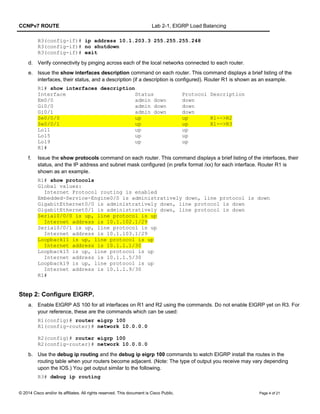
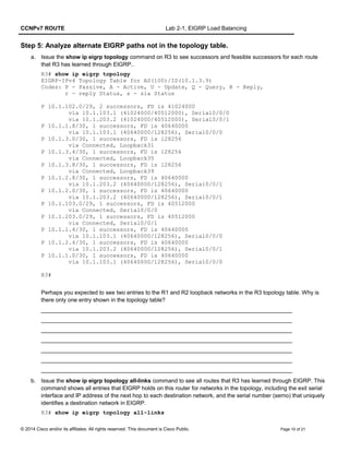
R1(config)# interface serial 0/0/0
R1(config-if)# bandwidth 128
R1(config-if)# clock rate 128000
R1(config-if)# interface serial 0/0/1
R1(config-if)# bandwidth 128
R2(config)# interface serial 0/0/0
R2(config-if)# bandwidth 128
R3(config)# interface serial 0/0/0
R3(config-if)# clock rate 128000
R3(config-if)# bandwidth 128
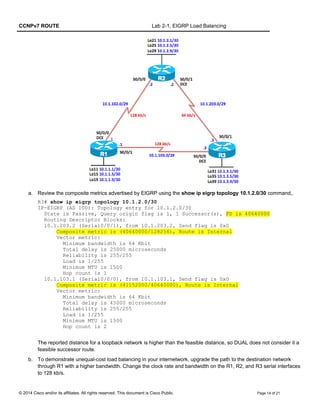
c. Issue the show ip eigrp topology 10.1.2.0/30 command again on R3 to see what has changed.
R3# show ip eigrp topology 10.1.2.0/30
EIGRP-IPv4 Topology Entry for AS(100)/ID(10.1.3.9) for 10.1.2.0/30
State is Passive, Query origin flag is 1, 1 Successor(s), FD is 21152000
Descriptor Blocks:
10.1.103.1 (Serial0/0/0), from 10.1.103.1, Send flag is 0x0
Composite metric is (21152000/20640000), route is Internal
Vector metric:
Minimum bandwidth is 128 Kbit
Total delay is 45000 microseconds
Reliability is 255/255
Load is 1/255
Minimum MTU is 1500
Hop count is 2
Originating router is 10.1.2.9
10.1.203.2 (Serial0/0/1), from 10.1.203.2, Send flag is 0x0
Composite metric is (40640000/128256), route is Internal
Vector metric:
Minimum bandwidth is 64 Kbit
Total delay is 25000 microseconds
Reliability is 255/255
Load is 3/255
Minimum MTU is 1500
Hop count is 1
Originating router is 10.1.2.9
R3#
After manipulating the bandwidth parameter, the preferred path for R3 to the loopback interfaces of R2 is now
through R1. Even though the hop count is two and the delay through R1 is nearly twice that of the R2 path, the
higher bandwidth and lower FD results in this being the preferred route.
Note: Hop count is only mentioned to help you visualize the two paths. Hop count is not part of the composite
EIGRP metric.
d. Issue the show ip route command to verify that the preferred route to network 10.1.2.0 is through R1 via
Serial0/0/0 to next hop 10.1.103.1. There is only one route to this network due to the difference in bandwidth.
R3# show ip route eigrp
<output omitted>
10.0.0.0/8 is variably subnetted, 17 subnets, 3 masks
D 10.1.1.0/30 [90/20640000] via 10.1.103.1, 00:05:09, Serial0/0/0
D 10.1.1.4/30 [90/20640000] via 10.1.103.1, 00:05:09, Serial0/0/0
D 10.1.1.8/30 [90/20640000] via 10.1.103.1, 00:05:09, Serial0/0/0
© 2014 Cisco and/or its affiliates. All rights reserved. This document is Cisco Public. Page 15 of 21](https://image.slidesharecdn.com/ccnpv7routelab2-1eigrp-load-balancingstudent-160718181051/85/Ccn-pv7-route_lab2-1_eigrp-load-balancing_student-15-320.jpg)
![CCNPv7 ROUTE Lab 2-1, EIGRP Load Balancing
D 10.1.2.0/30 [90/21152000] via 10.1.103.1, 00:05:09, Serial0/0/0
D 10.1.2.4/30 [90/21152000] via 10.1.103.1, 00:05:09, Serial0/0/0
D 10.1.2.8/30 [90/21152000] via 10.1.103.1, 00:05:09, Serial0/0/0
D 10.1.102.0/29 [90/21024000] via 10.1.103.1, 00:05:09, Serial0/0/0
R3#
e. The variance command is used to enable unequal-cost load balancing. Setting the variance command allows
you to install multiple loop-free paths with unequal costs into the routing table. EIGRP will always install the
successor with the best path. Additional feasible successors are candidates as for unequal-cost paths to be
included in the routing table. These candidates must meet two conditions:
• The route must be loop-free, a current feasible successor in the topology table.
• The metric of the route must be lower than the metric of the best route (successor), multiplied by the
variance configured on the router.
In the previous output, R3 shows the best path for 10.1.2.0/30 through R1 via 10.1.103.1. Examining the topology
table on R3, there is also a feasible successor to this network through R2 via 10.1.203.1.
R3# show ip eigrp topology
EIGRP-IPv4 Topology Table for AS(100)/ID(10.1.3.9)
Codes: P - Passive, A - Active, U - Update, Q - Query, R - Reply,
r - reply Status, s - sia Status
P 10.1.102.0/29, 1 successors, FD is 21024000
via 10.1.103.1 (21024000/20512000), Serial0/0/0
via 10.1.203.2 (41024000/20512000), Serial0/0/1
P 10.1.1.8/30, 1 successors, FD is 20640000
via 10.1.103.1 (20640000/128256), Serial0/0/0
P 10.1.3.0/30, 1 successors, FD is 128256
via Connected, Loopback31
P 10.1.3.4/30, 1 successors, FD is 128256
via Connected, Loopback35
P 10.1.3.8/30, 1 successors, FD is 128256
via Connected, Loopback39
P 10.1.2.8/30, 1 successors, FD is 21152000
via 10.1.103.1 (21152000/20640000), Serial0/0/0
via 10.1.203.2 (40640000/128256), Serial0/0/1
P 10.1.2.0/30, 1 successors, FD is 21152000
via 10.1.103.1 (21152000/20640000), Serial0/0/0
via 10.1.203.2 (40640000/128256), Serial0/0/1
P 10.1.103.0/29, 1 successors, FD is 20512000
via Connected, Serial0/0/0
P 10.1.203.0/29, 1 successors, FD is 40512000
via Connected, Serial0/0/1
P 10.1.1.4/30, 1 successors, FD is 20640000
via 10.1.103.1 (20640000/128256), Serial0/0/0
P 10.1.2.4/30, 1 successors, FD is 21152000
via 10.1.103.1 (21152000/20640000), Serial0/0/0
via 10.1.203.2 (40640000/128256), Serial0/0/1
P 10.1.1.0/30, 1 successors, FD is 20640000
via 10.1.103.1 (20640000/128256), Serial0/0/0
R3#
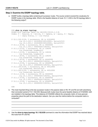
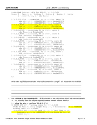
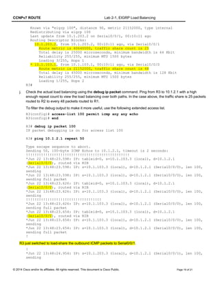
f. Issue the debug ip eigrp 100 command on R3 to show route events changing in real time. Then, under the
EIGRP router configuration on R3, issue the variance 2 command, which allows unequal-cost load balancing
bounded by a maximum distance of (2) × (FD), where FD represents the feasible distance for each route in the
routing table. Using 10.1.2.0/30 as an example, (2) x (21152000) = 42304000. The FD of the feasible successor is
© 2014 Cisco and/or its affiliates. All rights reserved. This document is Cisco Public. Page 16 of 21](https://image.slidesharecdn.com/ccnpv7routelab2-1eigrp-load-balancingstudent-160718181051/85/Ccn-pv7-route_lab2-1_eigrp-load-balancing_student-16-320.jpg)
![CCNPv7 ROUTE Lab 2-1, EIGRP Load Balancing
40640000 which is less that the variance-modified FD of 42304000. Therefore, the feasible successor route
become an additional successor and is added to the routing table.
R3# debug ip eigrp 100
EIGRP-IPv4 Route Event debugging is on for AS(100)
R3# conf t
Enter configuration commands, one per line. End with CNTL/Z.
R3(config)# router eigrp 100
R3(config-router)# variance 2
R3(config-router)#
*Jun 22 13:16:19.087: EIGRP-IPv4(100): table(default): route installed for
10.1.102.0/29 (90/21024000) origin(10.1.103.1)
*Jun 22 13:16:19.087: EIGRP-IPv4(100): table(default): route installed for
10.1.102.0/29 (90/41024000) origin(10.1.203.2)
*Jun 22 13:16:19.091: EIGRP-IPv4(100): table(default): route installed for
10.1.1.8/30 (90/20640000) origin(10.1.103.1)
*Jun 22 13:16:19.091: EIGRP-IPv4(100): table(default): 10.1.1.8/30 routing table
not updated thru 10.1.203.2
*Jun 22 13:16:19.091: EIGRP-IPv4
R3(config-router)#(100): table(default): route installed for 10.1.2.8/30
(90/21152000) origin(10.1.103.1)
*Jun 22 13:16:19.091: EIGRP-IPv4(100): table(default): route installed for
10.1.2.8/30 (90/40640000) origin(10.1.203.2)
*Jun 22 13:16:19.091: EIGRP-IPv4(100): table(default): route installed for
10.1.2.0/30 (90/21152000) origin(10.1.103.1)
*Jun 22 13:16:19.091: EIGRP-IPv4(100): table(default): route installed for
10.1.2.0/30 (90/40640000) origin(10.1.203.2)
*Jun 22 13:16:19.091: EIGRP-IPv4(100): table(default): 10.1
R3(config-router)#.103.0/29 routing table not updated thru 10.1.203.2
*Jun 22 13:16:19.091: EIGRP-IPv4(100): table(default): route installed for
10.1.1.4/30 (90/20640000) origin(10.1.103.1)
*Jun 22 13:16:19.091: EIGRP-IPv4(100): table(default): 10.1.1.4/30 routing table
not updated thru 10.1.203.2
*Jun 22 13:16:19.091: EIGRP-IPv4(100): table(default): route installed for
10.1.2.4/30 (90/21152000) origin(10.1.103.1)
*Jun 22 13:16:19.091: EIGRP-IPv4(100): table(default): route installed for
10.1.2.4/30 (90/40640000) origi
R3(config-router)#n(10.1.203.2)
*Jun 22 13:16:19.091: EIGRP-IPv4(100): table(default): route installed for
10.1.1.0/30 (90/20640000) origin(10.1.103.1)
*Jun 22 13:16:19.091: EIGRP-IPv4(100): table(default): 10.1.1.0/30 routing table
not updated thru 10.1.203.2
*Jun 22 13:16:19.103: EIGRP-IPv4(100): table(default): 10.1.102.0/29 - do advertise
out Serial0/0/0
<output omitted>
g. Issue the show ip route command again to verify that there are now two routes to network 10.1.2.0. Notice that
the two routes have different (unequal) metrics (feasible distances).
R3# show ip route eigrp
10.0.0.0/8 is variably subnetted, 17 subnets, 3 masks
D 10.1.1.0/30 [90/20640000] via 10.1.103.1, 00:05:56, Serial0/0/0
D 10.1.1.4/30 [90/20640000] via 10.1.103.1, 00:05:56, Serial0/0/0
D 10.1.1.8/30 [90/20640000] via 10.1.103.1, 00:05:56, Serial0/0/0
D 10.1.2.0/30 [90/40640000] via 10.1.203.2, 00:05:56, Serial0/0/1
[90/21152000] via 10.1.103.1, 00:05:56, Serial0/0/0
D 10.1.2.4/30 [90/40640000] via 10.1.203.2, 00:05:56, Serial0/0/1
© 2014 Cisco and/or its affiliates. All rights reserved. This document is Cisco Public. Page 17 of 21](https://image.slidesharecdn.com/ccnpv7routelab2-1eigrp-load-balancingstudent-160718181051/85/Ccn-pv7-route_lab2-1_eigrp-load-balancing_student-17-320.jpg)
![CCNPv7 ROUTE Lab 2-1, EIGRP Load Balancing
[90/21152000] via 10.1.103.1, 00:05:56, Serial0/0/0
D 10.1.2.8/30 [90/40640000] via 10.1.203.2, 00:05:56, Serial0/0/1
[90/21152000] via 10.1.103.1, 00:05:56, Serial0/0/0
D 10.1.102.0/29 [90/41024000] via 10.1.203.2, 00:05:56, Serial0/0/1
[90/21024000] via 10.1.103.1, 00:05:56, Serial0/0/0
R3#
h. These unequal-cost routes also show up in the EIGRP topology table as an additional successor. Use the show
ip eigrp topology command to verify this. Notice there are two successor routes with different (unequal) feasible
distances.
R3# show ip eigrp topology
EIGRP-IPv4 Topology Table for AS(100)/ID(10.1.3.9)
Codes: P - Passive, A - Active, U - Update, Q - Query, R - Reply,
r - reply Status, s - sia Status
P 10.1.102.0/29, 2 successors, FD is 21024000
via 10.1.103.1 (21024000/20512000), Serial0/0/0
via 10.1.203.2 (41024000/20512000), Serial0/0/1
P 10.1.1.8/30, 1 successors, FD is 20640000
via 10.1.103.1 (20640000/128256), Serial0/0/0
P 10.1.3.0/30, 1 successors, FD is 128256
via Connected, Loopback31
P 10.1.3.4/30, 1 successors, FD is 128256
via Connected, Loopback35
P 10.1.3.8/30, 1 successors, FD is 128256
via Connected, Loopback39
P 10.1.2.8/30, 2 successors, FD is 21152000
via 10.1.203.2 (40640000/128256), Serial0/0/1
via 10.1.103.1 (21152000/20640000), Serial0/0/0
P 10.1.2.0/30, 2 successors, FD is 21152000
via 10.1.203.2 (40640000/128256), Serial0/0/1
via 10.1.103.1 (21152000/20640000), Serial0/0/0
P 10.1.103.0/29, 1 successors, FD is 20512000
via Connected, Serial0/0/0
P 10.1.203.0/29, 1 successors, FD is 40512000
via Connected, Serial0/0/1
P 10.1.1.4/30, 1 successors, FD is 20640000
via 10.1.103.1 (20640000/128256), Serial0/0/0
P 10.1.2.4/30, 2 successors, FD is 21152000
via 10.1.203.2 (40640000/128256), Serial0/0/1
via 10.1.103.1 (21152000/20640000), Serial0/0/0
P 10.1.1.0/30, 1 successors, FD is 20640000
via 10.1.103.1 (20640000/128256), Serial0/0/0
R3#
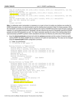
i. Load balancing over serial links occurs in blocks of packets, the number of which are recorded in the routing
table’s detailed routing information. Use the show ip route 10.1.2.0 command to get a detailed view of how traffic
is shared between the two links. The traffic share counters represent the ratio of traffic over the shared paths. In
this case the ratio is 48:25 or about 2-to-1. The path through R1, 10.1.103.1, will be sent twice as much traffic as
the path through R2, 10.1.203.2. A traffic share count of 1 on all routes indicates equal cost load balancing. If the
traffic share count is 0, the path is not in use.
R3# show ip route 10.1.2.0
Routing entry for 10.1.2.0/30
© 2014 Cisco and/or its affiliates. All rights reserved. This document is Cisco Public. Page 18 of 21](https://image.slidesharecdn.com/ccnpv7routelab2-1eigrp-load-balancingstudent-160718181051/85/Ccn-pv7-route_lab2-1_eigrp-load-balancing_student-18-320.jpg)

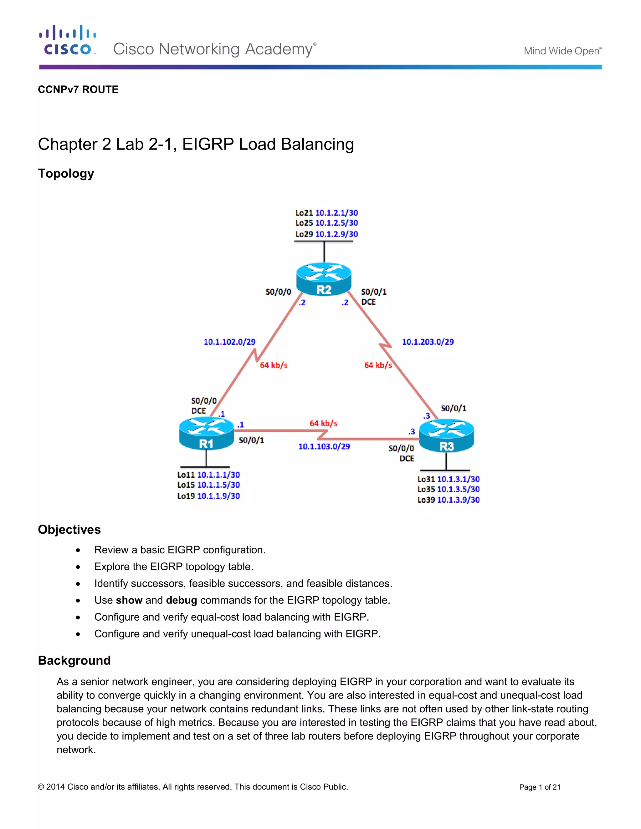
The document describes a lab that explores EIGRP load balancing capabilities. The objectives are to configure EIGRP on three routers, examine the EIGRP topology table, and verify equal-cost and unequal-cost load balancing. Initial configurations are provided to set up loopback interfaces and serial links between the routers. EIGRP is then enabled on two routers and debugging commands are used to observe route installation.