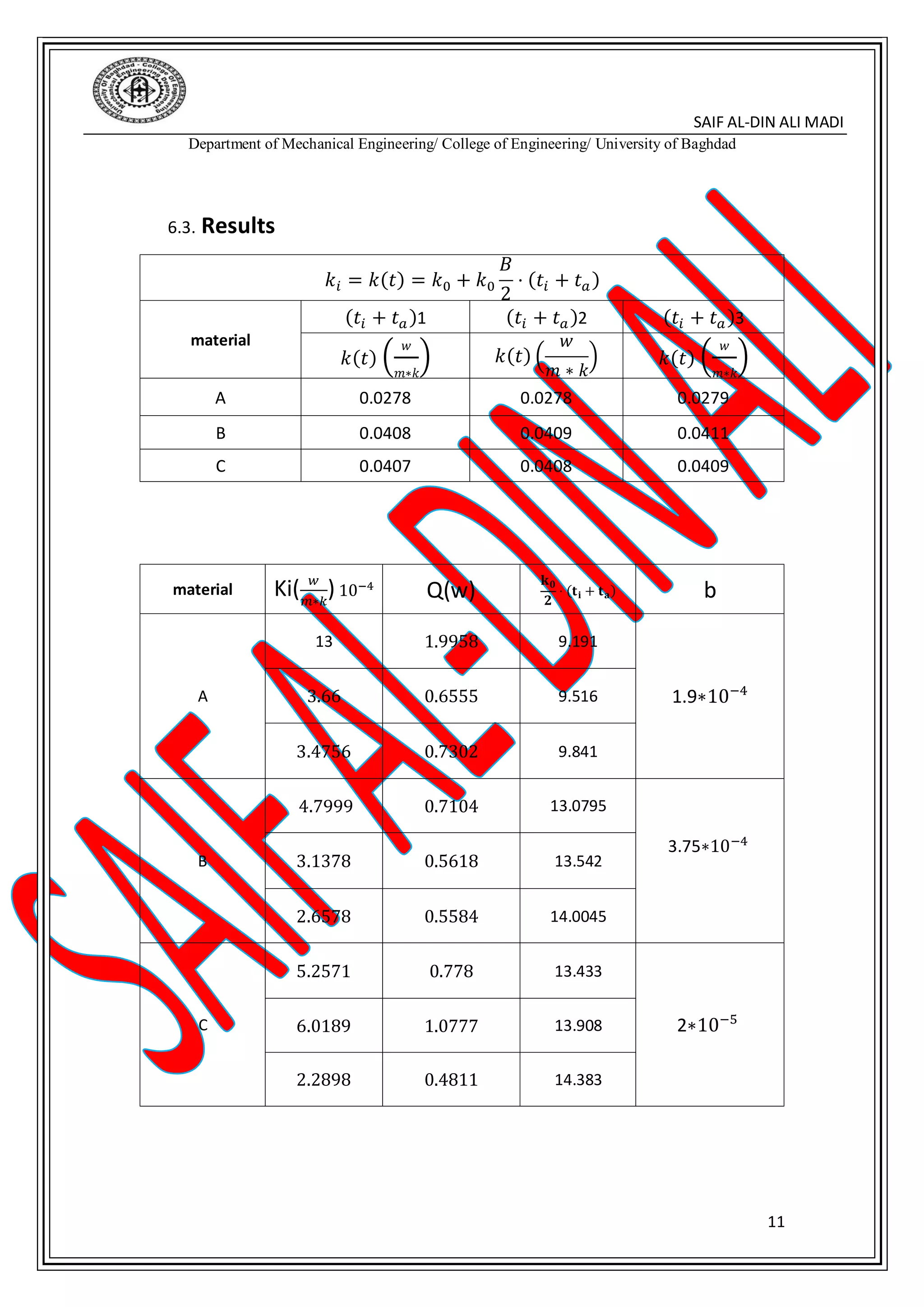
The document describes an experiment to study the efficiency of pipe insulation. Steam is passed through four vertical pipes - three covered with different insulating materials and one uncovered. The amount of condensate collected from each pipe is measured to calculate the heat lost and determine the thermal conductivity of the insulating materials. Calculations are shown for the three insulated pipes using parameters like steam temperature and pressure, insulation thickness, and condensate mass. The thermal conductivity is found to vary with temperature for each material.
Heart Disease Prediction using machine learning.pptx
Pipe Insulation Efficiency Study
1. SAIF AL-DIN ALI MADI
Department of Mechanical Engineering/ College of Engineering/ University of Baghdad
1
[HEAT TRANSFER Laboratory II]
University of Baghdad
Name: - Saif Al-din Ali -B-
2. SAIF AL-DIN ALI MADI
Department of Mechanical Engineering/ College of Engineering/ University of Baghdad
2
TABLE OF CONTENTS
Experiment Name................................................................I
Experiment Aim..............................................................II
Composition...................................................................V
THEORY..........................................................................VI
Calculations and results................................................VII
DISCUSSION……………….................................................VIII
3. SAIF AL-DIN ALI MADI
Department of Mechanical Engineering/ College of Engineering/ University of Baghdad
3
1. Experiment Name: Pipe Insulation Efficiency Study Unit
2. Experiment Aim: The study unit for the assessment of thermal
insulation efficiency permits investigating the effect of thermal
insulation of steam pipes, the unit consist of a set of four pipes, three of
which are covered with insulating materials, placed vertically. Steam is
fed by means of an overhead manifold
3. Composition:
The lagging of piping unit includes:
1. - 3 test pipes covered with materials which thermal conductivity
coefficient is different.
2. One pipe without covering,
3. Manual control valve on steam inlet,
4. Bourdon pressure gauge on steam inlet
5. Thermometer in steam inlet
6. Condenser discharge system,
7. Graduated containers of glass to measure the condensate,
4. Testing procedure ;-
1. Connect the study unit to the boiler plant,
2. Verify that steam arrives at the study unit,
3. Open the discharge valves and let the condensate flow down
4. Open the steam inlet valve
5. Wait until the study unit reaches thermal steady conditions,
6. Start the test: allow the steam to pass for a suitable time,
7. Weigh the containers to measure the mass of condensate
5. Theory:
Steam is transferred from a steam plant element to another by means
of pipes, often of considering length, As the steam is obviously at a much
higher temperature than atmosphere, the heat energy is lost all around.
Pipes must be insulated to minimize this loss: this is the purpose of the
covering with a suitable low conductivity material. This process is known
as lagging
4. SAIF AL-DIN ALI MADI
Department of Mechanical Engineering/ College of Engineering/ University of Baghdad
4
5.1. Calculation of heat flow rate;
We can assume that, if steam passes through a pipe, heat energy will be
lost at constant pressure, then the enthalpy h, of the steam will be
reduced,
Now:
In case of superheated steam from steam table: ℎ = 𝑓(𝑝.𝑡)
Or for wet steam ℎ = h 𝑓 + x ℎ 𝑓𝑔
Where
h 𝑓 = liquid enthalpy (from steam table at the steam pressure (P))
ℎ 𝑓𝑔= condensation / vaporization enthalpy (latent heat) (from steam table at
the steam pressure
x = dryness fraction, may be determined if the steam supply system is
equipped with a throttling calorimeter
If 1 and 2 are the conditions at the top and at the bottom of the pipe
respectively (Fig1), then:
In case of superheated steam:
ℎ 1 = 𝑓(𝑝1.𝑡1) 𝑎𝑛𝑑 ℎ 2 = 𝑓(𝑝2.𝑡2)
Or wet steam: ℎ1 = h 𝑓1 + 𝑥1 ℎ 𝑓𝑔1 and ℎ2 = h 𝑓2 + 𝑥2 ℎ 𝑓𝑔2
The rate of heat loss from the pipe: 𝑄`
= 𝑚`
(ℎ1 − ℎ2)
In case of wet steam and P2 = P1 then: ℎ1 − ℎ2 = (𝑥1 − 𝑥2) ℎ 𝑓𝑔
For case study Fig. (2): p2=p1 , 𝑥2 = 0
This means that the steam will condense as it passes through the pipe, hence:
In case of superheated steam; 𝑄`
= 𝑚`
(ℎ1 − ℎ 𝑓1)
Where 𝑚`
mass of condensate) / time
5. SAIF AL-DIN ALI MADI
Department of Mechanical Engineering/ College of Engineering/ University of Baghdad
5
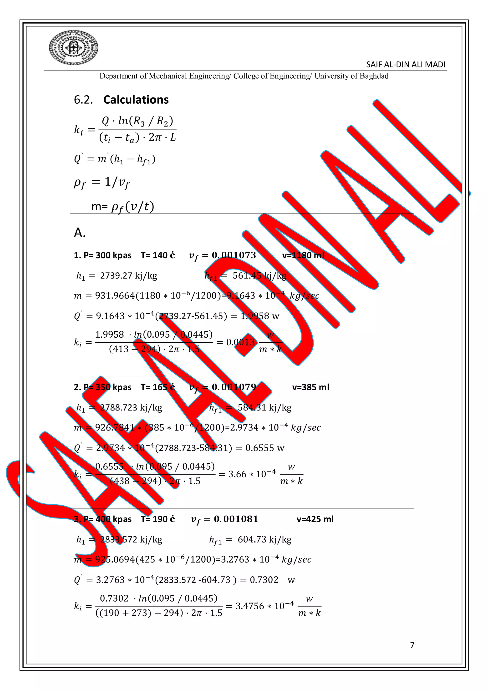
5.2. Calculation of thermal conductivity :
Heat is transferred by means of conduct through the lagging and by means of
convection from the outer surface, The rate of heat transfer is given by:
𝑄 = (
𝑡𝑖 + 𝑡 𝑎
𝑅 𝑡ℎ
)
Where :
𝑡𝑖 = steam temperature;
𝑡 𝑎= air temperature;
𝑅 𝑡ℎ = total thermal resistance which is given by:
𝑅𝑡ℎ =
𝐿𝑛(𝑅3 ∕ 𝑅2)
2𝜋 ∗ 𝑘𝑖 ∗ 𝐿
+
1
2𝜋 ∗ ℎ ∗ 𝑅2 ∗ 𝐿
+
𝐿𝑛(𝑅2 ∕ 𝑅1)
2𝜋 ∗ 𝑘 𝑝 ∗ 𝐿
Where:
R1: inner radius of pipe;
R2: inner radius of lagging;
R3: outer radius of lagging:
I: length of lagged section;
𝑘 𝑝; [thermal conductivity of pipe [W / m K];
𝑘𝑖: thermal conductivity of material [W / m K];
ℎ: surface heat transfer coefficient [W / m * K].
So we can get a good approximation by neglecting
1
2𝜋∗ℎ∗𝑅2∗𝐿
+
𝐿𝑛(𝑅2∕𝑅1)
2𝜋∗𝑘 𝑝∗𝐿
Thus
(𝑡 𝑖−𝑡 𝑎)⋅2𝜋⋅𝑘𝑖⋅𝐿
𝑙𝑛(𝑅3∕𝑅2)
≡ 𝑄 = 𝑚′(ℎ1 − ℎ2)
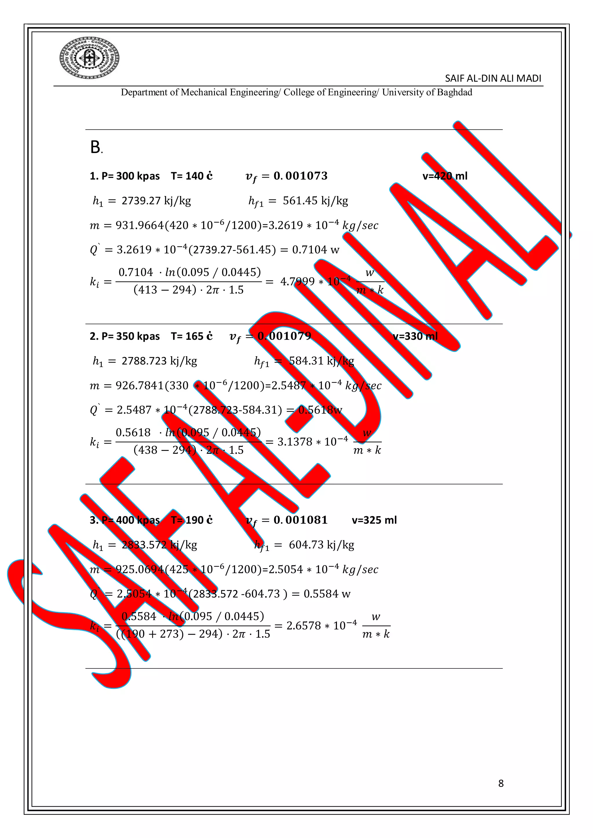
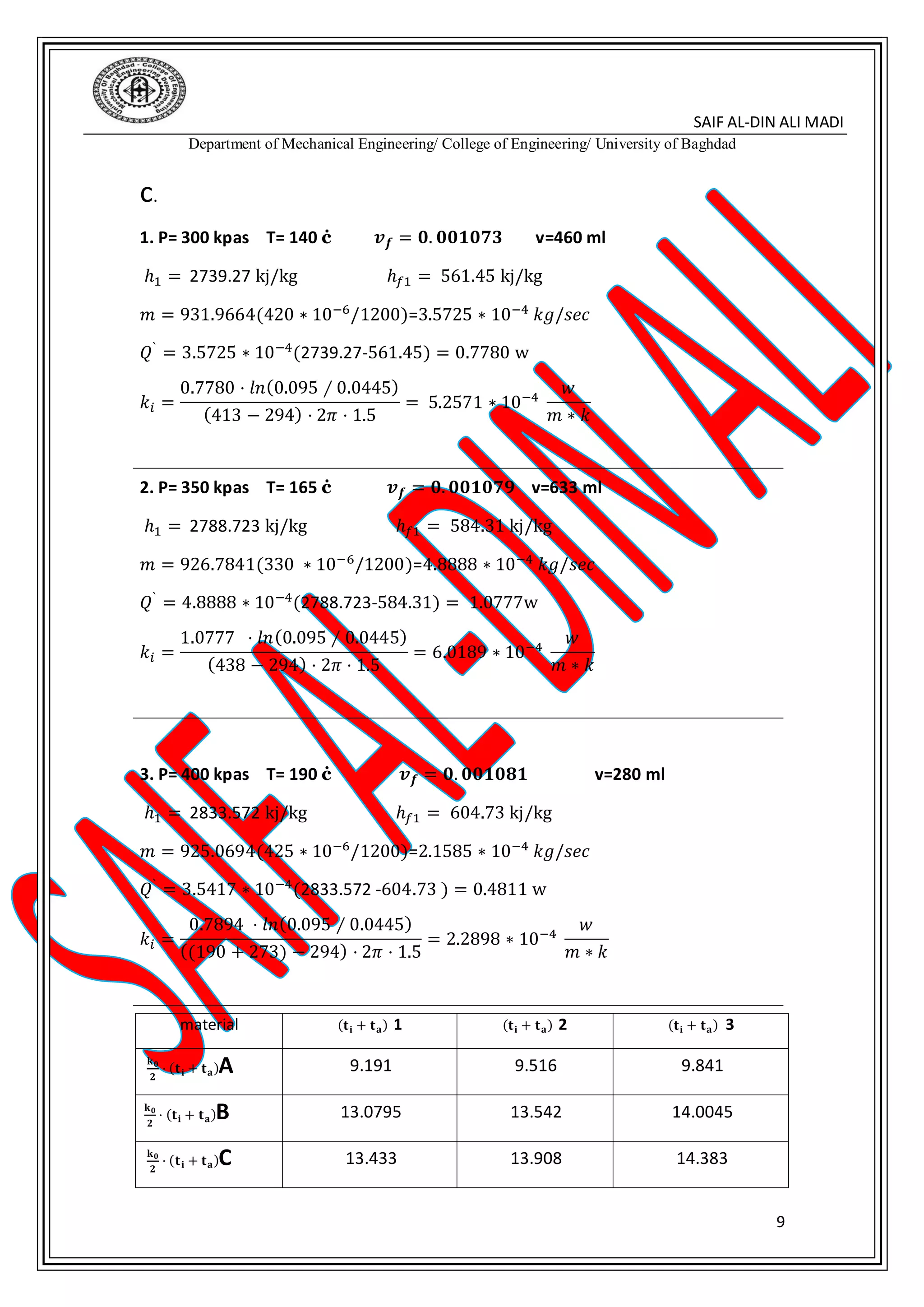
Then we can obtain thermal conductivity:
𝑘𝑖 =
𝑄 ⋅ 𝑙𝑛(𝑅3 ∕ 𝑅2)
(𝑡𝑖 − 𝑡 𝑎) ⋅ 2𝜋 ⋅ 𝐿
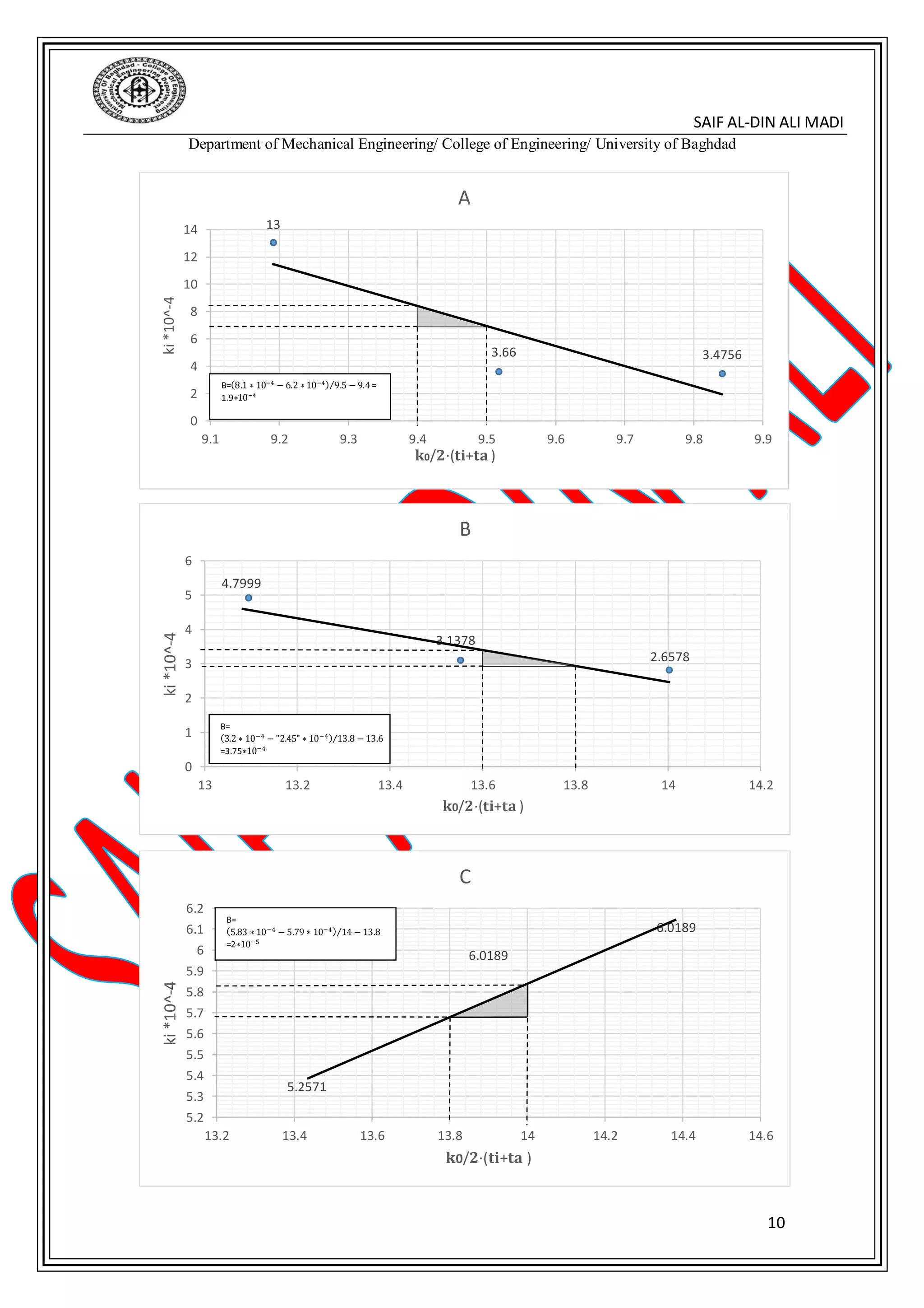
This thermal conductivity varies linearly with temperature because of the high temperature, The
variation of thermal conductivity with temperature is taken as:
𝑘𝑖 = 𝑘(𝑡) = 𝑘0 + 𝑘0
𝐵
2
⋅ (𝑡𝑖 + 𝑡 𝑎)
Where: 𝒌 𝟎: thermal conductivity at reference temperature taken from the apparatus)
b: constant
6. SAIF AL-DIN ALI MADI
Department of Mechanical Engineering/ College of Engineering/ University of Baghdad
6
6. Calculations and results
6.1. Information's
K(w/m*k)R(m)V(ml)T(ċ)P(bar)material
0.026
R1=0.041511801402
A R2=0.04453851652.5
R3=0.0954251903
0.037
R1=0.04134201402
B R2=0.04453301652.5
R3=0.0953251903
0.038
R1=0.04154601402
C R2=0.04456331652.5
R3=0.0252601903
t(sec)=1200
pa=1 bar
L=1500mm
Ta=21 c
11. SAIF AL-DIN ALI MADI
Department of Mechanical Engineering/ College of Engineering/ University of Baghdad
11
6.3. Results
𝑘𝑖 = 𝑘(𝑡) = 𝑘0 + 𝑘0
𝐵
2
⋅ (𝑡𝑖 + 𝑡 𝑎)
material
(𝑡𝑖 + 𝑡 𝑎)1 (𝑡𝑖 + 𝑡 𝑎)2 (𝑡𝑖 + 𝑡 𝑎)3
𝑘(𝑡) (
𝑤
𝑚∗𝑘
) 𝑘(𝑡) (
𝑤
𝑚 ∗ 𝑘
) 𝑘(𝑡) (
𝑤
𝑚∗𝑘
)
A 0.0278 0.0278 0.0279
B 0.0408 0.0409 0.0411
C 0.0407 0.0408 0.0409
material Ki( 𝑤
𝑚∗𝑘
) 10−4
Q(w)
𝐤 𝟎
𝟐
⋅ (𝐭 𝐢 + 𝐭 𝐚) b
A
13 1.9958 9.191
1.9∗10−4
3.66 0.6555 9.516
3.4756 0.7302 9.841
B
4.7999 0.7104 13.0795
3.75∗10−4
3.1378 0.5618 13.542
2.6578 0.5584 14.0045
C
5.2571 0.778 13.433
2∗10−5
6.0189 1.0777 13.908
2.2898 0.4811 14.383
12. SAIF AL-DIN ALI MADI
Department of Mechanical Engineering/ College of Engineering/ University of Baghdad
12
7. Conclusions:
1. Comment the heat flow rate for each pipe and comment about
the advantages of insulation for steam piping.
Steam pipes are very important in engineering application and are widely used. The main
applications include household boilers, industrial steam generating plants, locomotives,
steam engines, different building works, etc. to name but a few. Lack of proper insulation
results in large energy losses which in turn cost a lot of money over time. Without proper
insulation, the amount of energy lost can be 10 times greater than the energy being delivered
through those pipes. Insulation is defined as those materials or combinations of materials
which retard the flow of heat energy by performing one or more of the following functions:
1. Conserve energy by reducing heat loss or gain
2. Control surface temperatures for personnel protection and comfort
3. Facilitate temperature control of a process
4. Prevent vapor flow and water condensation on cold surfaces
5. Increase operating efficiency of heating/ventilating/cooling, plumbing, steam, process and
power systems found in commercial and industrial installations
6. Prevent or reduce damage to equipment from exposure to fire or corrosive atmospheres
Note that each flow pipe is different from the other because of the
process of insulation in the process of insulation depends on the
coefficient of insulation K The lower the amount of this coefficient was
excellent insulation process and this is what is included in the experiment
13. SAIF AL-DIN ALI MADI
Department of Mechanical Engineering/ College of Engineering/ University of Baghdad
13
2. Which material do you consider to have the best insulating
properties?
1. Fiberglass
Fiberglass is the most common insulation used in modern times. Because of how it is made,
by effectively weaving fine strands of glass into an insulation material, fiberglass is able to
minimize heat transfer. The main downside of fiberglass is the danger of handling it. Since
fiberglass is madeoutoffinely woven silicon, glass powder and tiny shards ofglass areformed.
These can cause damage to the eyes, lungs, and even skin if the proper safety equipment isn’t
worn. Nevertheless, when the proper safety equipment is used, fiberglass installation can be
performed without incident.
2. Mineral Wool
Mineral wool actually refers to several different types of insulation. First, it may refer to glass
wool which is fiberglass manufactured from recycled glass. Second, it may refer to rock wool
which is a type of insulation made from basalt. Finally, it may refer to slag wool which is
produced from the slag from steel mills. The majority of mineral wool in the United States is
actually slag wool.
3. Cellulose
Cellulose insulation is perhaps one of the most eco-friendly forms of insulation. Cellulose is
made from recycled cardboard, paper, and other similar materials and comes in loose form.
Cellulose has an R-value between R-3.1 and R-3.7. Some recent studies on cellulose have
shown that it might be an excellent product for use in minimizing fire damage. Because of the
compactness of the material, cellulose contains next to no oxygen within it. Without oxygen
within the material, this helps to minimize the amount of damage that a fire can cause.
4. Polyurethane Foam
While not the most abundant of insulations, polyurethane foams are an excellent form of
insulation. Nowadays, polyurethane foams use non-chlorofluorocarbon (CFC) gas for use as a
blowing agent. This helps to decrease the amount of damage to the ozone layer. They are
relatively light, weighing approximately two pounds per cubic foot (2 lb/ft^3). They have an
R-value of approximately R-6.3 per inch of thickness. There are also low density foams that
can be sprayed into areas thathave no insulation. These types of polyurethane insulation tend
to have approximately R-3.6 rating per inch of thickness. Another advantage of this type of
insulation is that it is fire resistant.
5. Polystyrene
Polystyrene is a waterproof thermoplastic foam which is an excellent sound and temperature
insulation material. It comes in two types, expanded (EPS) and extruded (XEPS) also known as
Styrofoam. The two types differ in performance ratings and cost. The more costly XEPS has a
R-value of R-5.5 while EPS is R-4. Polystyrene insulation has a uniquely smooth surface which
no other type of insulation possesses.
14. SAIF AL-DIN ALI MADI
Department of Mechanical Engineering/ College of Engineering/ University of Baghdad
14
3. Calculate the thermal conductivities of the materials used and
compare these values with those quoted for the commercial
materials.
The first part was answered
Can not compare because of the large difference resulting from the
device
4. Comment on discrepancies (if any).
The practical tests are not without errors resulting from the device or the
process of dealing with the experience in taking readings and calibrating
the measuring devices. Measuring the temperature and pressure and
calculating the volume of water with time. The process is not accurate.
5. How could this test carried out with greater accuracy
Through the development of the laboratory device and the introduction
of electronic sensors for reading the temperature and flow rate meters
for water and periodic maintenance of the device and the process of
continuous calibration and attention to safety aspects because we deal
with high temperatures and pressures