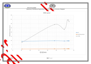
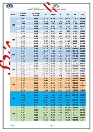
Saif al-din ali Madi
Department of Mechanical Engineering/ College of Engineering/ University of Baghdad
20/4/2019 1 | P a g e
[Fluid Laboratory II]
University of Baghdad
Name: - Saif Al-din Ali -B-
Saif al-din ali Madi
Department of Mechanical Engineering/ College of Engineering/ University of Baghdad
20/4/2019 2 | P a g e
TABLE OF CONTENTS
ABSTRACT.........................................................................I
OBJECTIVE......................................................................II
INTRODUCTION...........................................................III
APPARATUS.....................................................................V
Drawing relationships ....................................................VI
Saif al-din ali Madi
Department of Mechanical Engineering/ College of Engineering/ University of Baghdad
20/4/2019 3 | P a g e
Experiment Name:- Centrifugal fan
1. Abstract
The fan is being run with an electric motor and then taking the
readings from the sensors associated with the processor and the
computer and drawing the ratios relative to the flow
2. OBJECTIVE
A practical study of Centrifugal type fan and the study of the boundary relations
practically extracted
3. INTRODUCTION
A fan is a device that utilizes the mechanical energy of a rotating impeller to
produce both movement of the air and an increase in its total pressure. The
great majority of fans used in mining are driven by electric motors, although
internal combustion engines may be employed, particularly as a standby on
surface fans. Compressed air or water turbines may be used to drive small
fans in abnormally gassy or hot conditions, or where an electrical power
supply is unavailable.
A centrifugal fan resembles a paddle wheel. Air enters near the centre of the
wheel, turns through a right angle and moves radially outward by centrifugal
action between the blades of the rotating impeller. Those blades may be
straight or curved either backwards or forwards with respect to the direction of
rotation. Each of these designs produces a distinctive performance
characteristic. Inlet and/or outlet guide vanes may be fitted to vary the
performance of a centrifugal fan
Centrifugal fans are constant-displacement or constant-volume devices,
meaning that, at a constant fan speed, a centrifugal fan moves a relatively
constant volume of air rather than a constant mass. This means that the air
velocity in a system is fixed even though the mass flow rate through the fan is
not
Saif al-din ali Madi
Department of Mechanical Engineering/ College of Engineering/ University of Baghdad
20/4/2019 4 | P a g e
A- Forward-curved
Forward-curved blades, as in Figure (a), curve in the direction of the fan
wheel's rotation. These are especially sensitive to particulates and commonly
are only specified for clean-air applications such as air conditioning. Forward-
curved blades provide a low noise level and relatively small air flow with a
high increase in static pressure
B- Backward-curved
Backward-curved blades, as in Figure (b), curve against the direction of the
fan wheel's rotation. Smaller blowers may have backward-inclined blades,
which are straight, not curved. Larger backward-inclined/-curved blowers have
blades whose backward curvatures mimic that of an airfoil cross section, but
both designs provide good operating efficiency with relatively economical
construction techniques. These types of blowers are designed to handle gas
streams with low to moderate particulate loadings. They can be easily fitted
with wear protection but certain blade curvatures can be prone to solids build-
up. Backward curved wheels are often heavier than corresponding forward-
curved equivalents, as they run at higher speeds and require stronger
construction.
Backward curved fans can have a high range of specific speeds but are most
often used for medium specific speed applications—high pressure, medium
flow applications.
Backward-curved fans are much more energy efficient than radial blade fans
and so, for high power applications may be a suitable alternative to the lower
cost radial bladed fan.
C- Straight radial
Radial blowers, as in Figure (c), have wheels whose blades extend straight
out from the centre of the hub. Radial bladed wheels are often used on
particulate-laden gas streams because they are the least sensitive to solid
build-up on the blades, but they are often characterized by greater noise
output. High speeds, low volumes, and high pressures are common with
radial blowers, and are often used in, pneumatic material conveying systems,
and similar processes.
Saif al-din ali Madi
Department of Mechanical Engineering/ College of Engineering/ University of Baghdad
20/4/2019 5 | P a g e
Losses
Centrifugal fans suffer efficiency losses in both stationary and moving parts,
increasing the energy input required for a given level of airflow performance.
1. Impeller entry
Flow at the intake and its turning from axial to radial direction causes
losses at the intake. Friction and flow separation cause impeller blade
losses since there is change in incidence angle these impeller blade
losses are also included in the category.
2. Leakage
Leakage of some air and disturbance in the main flow field is caused due
to the clearance provided between the rotating periphery of the
impeller and the casing at the entry.
3. Impeller
Passage friction and flow separation cause impeller losses that depend
on relative velocity, rate of diffusion, and blade geometry. Impeller
dynamic balancing usually is done on a precision balancing machine,
because all energy of vibrational imbalance is lost (for example, this can
easily amount to 50% of air-flow loss in poorly-maintained home AC
units)
4. Diffuser and volute
Friction and flow separation also causes losses in the diffuser. Further
losses due to incidence occur if the device is working beyond its design
conditions. Flow from the impeller or diffuser expands in the volute,
which has a larger cross section leading to the formation of eddy, which
in turn reduces pressure head. Friction and flow separation losses also
occur due the volute passage.
5. Disc friction
Viscous drag on the back surface of the impeller disc causes disc friction
losses
Saif al-din ali Madi
Department of Mechanical Engineering/ College of Engineering/ University of Baghdad
20/4/2019 6 | P a g e
4. APPARATUS
The main parts of the centrifugal fan are:
1. Fan housing
2. Defenses
3. Inlet and outlet channels
4. Drive shaft
5. Automatic drive
Other components used may include bearings, connectors,
impeller locking device, propeller discharge casing, computer
pressure gauge and flow meters etc.
Saif al-din ali Madi
Department of Mechanical Engineering/ College of Engineering/ University of Baghdad
20/4/2019 7 | P a g e
5 .Drawing relationships
-0.05
0
0.05
0.1
0.15
0.2
0.25
0.3
0 10 20 30 40 50 60 70
dischargepresser
Q lt/min
1500
1750
2000
2250
2750
3000
Saif al-din ali Madi
Department of Mechanical Engineering/ College of Engineering/ University of Baghdad
20/4/2019 8 | P a g e
0
0.1
0.2
0.3
0.4
0.5
0.6
0.7
0.8
0.9
1
0 10 20 30 40 50 60 70
torque
Q lt/min
1500
1750
2000
2250
2500
2750
3000
Saif al-din ali Madi
Department of Mechanical Engineering/ College of Engineering/ University of Baghdad
20/4/2019 9 | P a g e
0
5
10
15
20
25
30
35
40
45
50
0 10 20 30 40 50 60 70
Eff%
Q lt/min
1500
1750
2000
2250
2750
Linear (3000)
Saif al-din ali Madi
Department of Mechanical Engineering/ College of Engineering/ University of Baghdad
20/4/2019 10 | P a g e
0
2
4
6
8
10
12
0 10 20 30 40 50 60 70
Hi
Q lt/min
1500
1750
2000
2250
2500
2750
3000
Saif al-din ali Madi
Department of Mechanical Engineering/ College of Engineering/ University of Baghdad
20/4/2019 11 | P a g e
0
20
40
60
80
100
120
0 10 20 30 40 50 60 70
Nh
Q lt/min
1500
1750
2000
2250
2500
2750
3000
Saif al-din ali Madi
Department of Mechanical Engineering/ College of Engineering/ University of Baghdad
20/4/2019 12 | P a g e
0
20
40
60
80
100
120
0 10 20 30 40 50 60 70
Nh&Eff&Hi&dischargepresser
Q lt/min
3000 speed
Hi
dischsrg presser
Eff%
Nh
Saif al-din ali Madi
Department of Mechanical Engineering/ College of Engineering/ University of Baghdad
20/4/2019 13 | P a g e
0
5
10
15
20
25
30
35
40
0 10 20 30 40 50 60 70
Eff&Hi&dischargepresser
Q lt/min
3000 speed
Hi
dischsrg presser
Eff%
Saif al-din ali Madi
Department of Mechanical Engineering/ College of Engineering/ University of Baghdad
20/4/2019 14 | P a g e
speed
suction
pressure
discharge
presser
Q torque Hi Nh Nm Eff%
1500
-0.094 0.091 38.576 0.409 3.336 21.041 64.318 32.715
-0.098 0.092 38.248 0.412 3.366 21.05 64.701 32.534
-0.11 0.086 37.63 0.41 3.39 20.858 64.329 32.424
-0.138 0.078 35.479 0.405 3.447 19.998 63.654 31.417
-0.204 0.054 31.425 0.349 3.643 18.721 62.736 29.84
-0.402 0.002 11.072 0.341 4.394 7.954 33.586 14.843
1750
-0.135 0.128 45.592 0.487 4.63 34.518 89.195 38.699
-0.14 0.124 44.955 0.483 4.594 33.767 88.567 38.126
-0.154 0.119 43.382 0.482 4.566 32.383 88.292 36.677
-0.018 0.107 41.47 0.474 4.665 31.629 86.92 36.388
-0.228 0.098 39.548 0.469 4.835 31.262 85.97 36.364
-0.446 0.032 24.172 0.443 5.536 21.886 81.113 26.982
2000
-0.179 0.166 50.829 0.573 5.907 49.088 119.965 40.119
-0.185 0.164 50.755 0.58 5.944 49.33 121.419 40.628
-0.202 0.155 49.111 0.568 5.874 47.167 118.924 39.661
-0.243 0.143 46.737 0.569 5.983 45.716 119.125 38.376
-0.357 0.106 40.954 0.554 6.326 42.359 116.079 36.492
-0.582 0.001 11.963 0.409 6.233 12.179 85.579 14.232
2250
-0.127 0.205 57.046 0.669 7.375 68.794 157.55 43.665
-0.219 0.194 54.917 0.659 6.969 62.577 155.368 40.276
-0.243 0.185 54.705 0.623 7.01 61.552 153.942 39.984
-0.286 0.17 51.235 0.646 7.083 59.333 152.27 38.966
-0.407 0.13 45.582 0.628 7.431 55.39 147.915 37.447
-0.066 0.004 12.341 0.467 7.18 14.362 110.032 13.052
2500
-0.248 0.226 59.565 0.733 8.056 78.452 191.469 40.861
-0.255 0.222 59.17 0.733 8.051 77.882 192.022 40.559
-0.278 0.208 57.526 0.734 7.973 74.988 192.267 39
-0.332 0.191 54.697 0.728 8.069 72.16 190.586 37.863
-0.484 0.138 46.701 0.717 8.383 64.003 183.295 34.91
-0.769 0.002 11.482 0.546 8.141 15.279 142.842 10.696
2750
-0.273 0.247 62.123 0.815 8.785 89.228 234.734 38.01
-0.285 0.244 61.594 0.81 8.822 88.849 233.312 38.081
-0.309 0.234 60.269 0.806 8.83 87.021 232.211 37.475
-0.366 0.213 58.131 0.807 8.975 85.297 232.536 36.681
-0.542 0.149 48.392 0.784 9.223 72.987 225.762 32.329
-0.832 -0.001 11.395 0.598 8.752 16.302 172.177 9.468
3000
-0.301 0.27 64.651 0.934 9.581 101.268 293.555 32.4397
-0.313 0.263 64.001 0.932 9.565 100.086 292.78 34.185
-0.341 0.251 62.759 0.916 9.594 98.443 287.61 34.228
-0.385 0.229 59.2 0.902 9.446 91.437 283.31 23.273
-0.598 0.146 47.993 0.841 9.732 76.366 264.041 28.922
-0.856 0.005 10.636 0.632 9.041 15.726 198.613 7.918

Fluid Laboratory | Centrifugal fan

  • 1.
    Saif al-din aliMadi Department of Mechanical Engineering/ College of Engineering/ University of Baghdad 20/4/2019 1 | P a g e [Fluid Laboratory II] University of Baghdad Name: - Saif Al-din Ali -B-
  • 2.
    Saif al-din aliMadi Department of Mechanical Engineering/ College of Engineering/ University of Baghdad 20/4/2019 2 | P a g e TABLE OF CONTENTS ABSTRACT.........................................................................I OBJECTIVE......................................................................II INTRODUCTION...........................................................III APPARATUS.....................................................................V Drawing relationships ....................................................VI
  • 3.
    Saif al-din aliMadi Department of Mechanical Engineering/ College of Engineering/ University of Baghdad 20/4/2019 3 | P a g e Experiment Name:- Centrifugal fan 1. Abstract The fan is being run with an electric motor and then taking the readings from the sensors associated with the processor and the computer and drawing the ratios relative to the flow 2. OBJECTIVE A practical study of Centrifugal type fan and the study of the boundary relations practically extracted 3. INTRODUCTION A fan is a device that utilizes the mechanical energy of a rotating impeller to produce both movement of the air and an increase in its total pressure. The great majority of fans used in mining are driven by electric motors, although internal combustion engines may be employed, particularly as a standby on surface fans. Compressed air or water turbines may be used to drive small fans in abnormally gassy or hot conditions, or where an electrical power supply is unavailable. A centrifugal fan resembles a paddle wheel. Air enters near the centre of the wheel, turns through a right angle and moves radially outward by centrifugal action between the blades of the rotating impeller. Those blades may be straight or curved either backwards or forwards with respect to the direction of rotation. Each of these designs produces a distinctive performance characteristic. Inlet and/or outlet guide vanes may be fitted to vary the performance of a centrifugal fan Centrifugal fans are constant-displacement or constant-volume devices, meaning that, at a constant fan speed, a centrifugal fan moves a relatively constant volume of air rather than a constant mass. This means that the air velocity in a system is fixed even though the mass flow rate through the fan is not
  • 4.
    Saif al-din aliMadi Department of Mechanical Engineering/ College of Engineering/ University of Baghdad 20/4/2019 4 | P a g e A- Forward-curved Forward-curved blades, as in Figure (a), curve in the direction of the fan wheel's rotation. These are especially sensitive to particulates and commonly are only specified for clean-air applications such as air conditioning. Forward- curved blades provide a low noise level and relatively small air flow with a high increase in static pressure B- Backward-curved Backward-curved blades, as in Figure (b), curve against the direction of the fan wheel's rotation. Smaller blowers may have backward-inclined blades, which are straight, not curved. Larger backward-inclined/-curved blowers have blades whose backward curvatures mimic that of an airfoil cross section, but both designs provide good operating efficiency with relatively economical construction techniques. These types of blowers are designed to handle gas streams with low to moderate particulate loadings. They can be easily fitted with wear protection but certain blade curvatures can be prone to solids build- up. Backward curved wheels are often heavier than corresponding forward- curved equivalents, as they run at higher speeds and require stronger construction. Backward curved fans can have a high range of specific speeds but are most often used for medium specific speed applications—high pressure, medium flow applications. Backward-curved fans are much more energy efficient than radial blade fans and so, for high power applications may be a suitable alternative to the lower cost radial bladed fan. C- Straight radial Radial blowers, as in Figure (c), have wheels whose blades extend straight out from the centre of the hub. Radial bladed wheels are often used on particulate-laden gas streams because they are the least sensitive to solid build-up on the blades, but they are often characterized by greater noise output. High speeds, low volumes, and high pressures are common with radial blowers, and are often used in, pneumatic material conveying systems, and similar processes.
  • 5.
    Saif al-din aliMadi Department of Mechanical Engineering/ College of Engineering/ University of Baghdad 20/4/2019 5 | P a g e Losses Centrifugal fans suffer efficiency losses in both stationary and moving parts, increasing the energy input required for a given level of airflow performance. 1. Impeller entry Flow at the intake and its turning from axial to radial direction causes losses at the intake. Friction and flow separation cause impeller blade losses since there is change in incidence angle these impeller blade losses are also included in the category. 2. Leakage Leakage of some air and disturbance in the main flow field is caused due to the clearance provided between the rotating periphery of the impeller and the casing at the entry. 3. Impeller Passage friction and flow separation cause impeller losses that depend on relative velocity, rate of diffusion, and blade geometry. Impeller dynamic balancing usually is done on a precision balancing machine, because all energy of vibrational imbalance is lost (for example, this can easily amount to 50% of air-flow loss in poorly-maintained home AC units) 4. Diffuser and volute Friction and flow separation also causes losses in the diffuser. Further losses due to incidence occur if the device is working beyond its design conditions. Flow from the impeller or diffuser expands in the volute, which has a larger cross section leading to the formation of eddy, which in turn reduces pressure head. Friction and flow separation losses also occur due the volute passage. 5. Disc friction Viscous drag on the back surface of the impeller disc causes disc friction losses
  • 6.
    Saif al-din aliMadi Department of Mechanical Engineering/ College of Engineering/ University of Baghdad 20/4/2019 6 | P a g e 4. APPARATUS The main parts of the centrifugal fan are: 1. Fan housing 2. Defenses 3. Inlet and outlet channels 4. Drive shaft 5. Automatic drive Other components used may include bearings, connectors, impeller locking device, propeller discharge casing, computer pressure gauge and flow meters etc.
  • 7.
    Saif al-din aliMadi Department of Mechanical Engineering/ College of Engineering/ University of Baghdad 20/4/2019 7 | P a g e 5 .Drawing relationships -0.05 0 0.05 0.1 0.15 0.2 0.25 0.3 0 10 20 30 40 50 60 70 dischargepresser Q lt/min 1500 1750 2000 2250 2750 3000
  • 8.
    Saif al-din aliMadi Department of Mechanical Engineering/ College of Engineering/ University of Baghdad 20/4/2019 8 | P a g e 0 0.1 0.2 0.3 0.4 0.5 0.6 0.7 0.8 0.9 1 0 10 20 30 40 50 60 70 torque Q lt/min 1500 1750 2000 2250 2500 2750 3000
  • 9.
    Saif al-din aliMadi Department of Mechanical Engineering/ College of Engineering/ University of Baghdad 20/4/2019 9 | P a g e 0 5 10 15 20 25 30 35 40 45 50 0 10 20 30 40 50 60 70 Eff% Q lt/min 1500 1750 2000 2250 2750 Linear (3000)
  • 10.
    Saif al-din aliMadi Department of Mechanical Engineering/ College of Engineering/ University of Baghdad 20/4/2019 10 | P a g e 0 2 4 6 8 10 12 0 10 20 30 40 50 60 70 Hi Q lt/min 1500 1750 2000 2250 2500 2750 3000
  • 11.
    Saif al-din aliMadi Department of Mechanical Engineering/ College of Engineering/ University of Baghdad 20/4/2019 11 | P a g e 0 20 40 60 80 100 120 0 10 20 30 40 50 60 70 Nh Q lt/min 1500 1750 2000 2250 2500 2750 3000
  • 12.
    Saif al-din aliMadi Department of Mechanical Engineering/ College of Engineering/ University of Baghdad 20/4/2019 12 | P a g e 0 20 40 60 80 100 120 0 10 20 30 40 50 60 70 Nh&Eff&Hi&dischargepresser Q lt/min 3000 speed Hi dischsrg presser Eff% Nh
  • 13.
    Saif al-din aliMadi Department of Mechanical Engineering/ College of Engineering/ University of Baghdad 20/4/2019 13 | P a g e 0 5 10 15 20 25 30 35 40 0 10 20 30 40 50 60 70 Eff&Hi&dischargepresser Q lt/min 3000 speed Hi dischsrg presser Eff%
  • 14.
    Saif al-din aliMadi Department of Mechanical Engineering/ College of Engineering/ University of Baghdad 20/4/2019 14 | P a g e speed suction pressure discharge presser Q torque Hi Nh Nm Eff% 1500 -0.094 0.091 38.576 0.409 3.336 21.041 64.318 32.715 -0.098 0.092 38.248 0.412 3.366 21.05 64.701 32.534 -0.11 0.086 37.63 0.41 3.39 20.858 64.329 32.424 -0.138 0.078 35.479 0.405 3.447 19.998 63.654 31.417 -0.204 0.054 31.425 0.349 3.643 18.721 62.736 29.84 -0.402 0.002 11.072 0.341 4.394 7.954 33.586 14.843 1750 -0.135 0.128 45.592 0.487 4.63 34.518 89.195 38.699 -0.14 0.124 44.955 0.483 4.594 33.767 88.567 38.126 -0.154 0.119 43.382 0.482 4.566 32.383 88.292 36.677 -0.018 0.107 41.47 0.474 4.665 31.629 86.92 36.388 -0.228 0.098 39.548 0.469 4.835 31.262 85.97 36.364 -0.446 0.032 24.172 0.443 5.536 21.886 81.113 26.982 2000 -0.179 0.166 50.829 0.573 5.907 49.088 119.965 40.119 -0.185 0.164 50.755 0.58 5.944 49.33 121.419 40.628 -0.202 0.155 49.111 0.568 5.874 47.167 118.924 39.661 -0.243 0.143 46.737 0.569 5.983 45.716 119.125 38.376 -0.357 0.106 40.954 0.554 6.326 42.359 116.079 36.492 -0.582 0.001 11.963 0.409 6.233 12.179 85.579 14.232 2250 -0.127 0.205 57.046 0.669 7.375 68.794 157.55 43.665 -0.219 0.194 54.917 0.659 6.969 62.577 155.368 40.276 -0.243 0.185 54.705 0.623 7.01 61.552 153.942 39.984 -0.286 0.17 51.235 0.646 7.083 59.333 152.27 38.966 -0.407 0.13 45.582 0.628 7.431 55.39 147.915 37.447 -0.066 0.004 12.341 0.467 7.18 14.362 110.032 13.052 2500 -0.248 0.226 59.565 0.733 8.056 78.452 191.469 40.861 -0.255 0.222 59.17 0.733 8.051 77.882 192.022 40.559 -0.278 0.208 57.526 0.734 7.973 74.988 192.267 39 -0.332 0.191 54.697 0.728 8.069 72.16 190.586 37.863 -0.484 0.138 46.701 0.717 8.383 64.003 183.295 34.91 -0.769 0.002 11.482 0.546 8.141 15.279 142.842 10.696 2750 -0.273 0.247 62.123 0.815 8.785 89.228 234.734 38.01 -0.285 0.244 61.594 0.81 8.822 88.849 233.312 38.081 -0.309 0.234 60.269 0.806 8.83 87.021 232.211 37.475 -0.366 0.213 58.131 0.807 8.975 85.297 232.536 36.681 -0.542 0.149 48.392 0.784 9.223 72.987 225.762 32.329 -0.832 -0.001 11.395 0.598 8.752 16.302 172.177 9.468 3000 -0.301 0.27 64.651 0.934 9.581 101.268 293.555 32.4397 -0.313 0.263 64.001 0.932 9.565 100.086 292.78 34.185 -0.341 0.251 62.759 0.916 9.594 98.443 287.61 34.228 -0.385 0.229 59.2 0.902 9.446 91.437 283.31 23.273 -0.598 0.146 47.993 0.841 9.732 76.366 264.041 28.922 -0.856 0.005 10.636 0.632 9.041 15.726 198.613 7.918