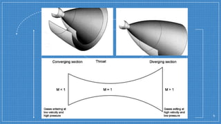
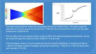
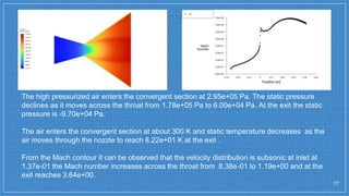
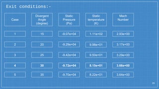
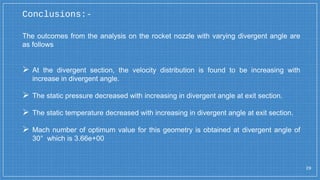
SlideShare a Scribd company logo
Simulation of convergent divergent
rocket nozzle using CFD analysis
By
Almukhtar A. Farhan
Supervised By
Dr. Iman Jabbar Ooda
University of Baghdad-College of Engineering
Aeronautical Engineering Department
INTRODUCTION:-
Rocket engines are reaction engines, manufacturing thrust by ejecting mass rearward, in
accordance with Newton's third law which could be an automation that is meant to
manage the speed of flow, speed direction and pressure of stream that exhaust through
the nozzle of that rocket. Most rocket engines use the combustion of reactive chemicals
to provide the mandatory energy, however non-combusting forms like cold gas thrusters
and nuclear thermal rockets additionally exist.
The nozzle is the final part of rockets that has the capacity to convert the thermo-
chemical energy generated in the combustion chamber into kinetic energy in order to
produce thrust by converting the low velocity, high pressure, high temperature (subsonic)
gases in the combustion chamber into high velocity (supersonic) gases of lower pressure
and temperature. The design of a nozzle including divergent angle and other parameters
has particular importance in determining the thrust and performance of a rocket..
2
There are many types of nozzles that usually used in rocket
engines and some of them are mentioned below.
3
• Cone (conical) nozzle:
• Bell (contoured) nozzle:
• Annular (plug) nozzle:
• Extendible nozzle
Convergent-Divergent Nozzle (De Laval Nozzle): -
Which is developed by Swedish inventor Gustaf de Laval in 1888 while he was trying to
develop a more efficient steam engine. It is a tube that pinched in the middle, making a
carefully balanced, asymmetric hourglass shape usually used if the nozzle pressure
ratio is high. it is used to accelerate a compressible fluid to supersonic speeds in the axial
direction, by converting the thermal energy of the flow into kinetic energy, where the flow
is accelerated from low subsonic to sonic velocity at the throat and further expanded to
supersonic velocity at the exit
Conical nozzle: -
4
Conical nozzles have a constant expansion rate and look like a cone, hence their name.
These nozzles tend to be the long and heavy in compare with other types of nozzles. They
do have the advantage however of being easy to manufacture and its simple cone shape
for design, and it contains no inflection as the propellants are expelled from the
combustion chamber. This lack of inflection is critical for solid and hybrid engines because
these types of engines usually have some pieces of solid propellant expelled all the way
out of the nozzle. Therefore, a conical nozzle is desired for solid and hybrid propellant
types due to the lack of inflection..
5
AIMS OF THE PROJECT:-
6
1. This project aims to analyze the variation of flow parameters like pressure, temperature
and Mach number inside a converging-diverging nozzle and conical nozzle.
2. Study the effect of divergent angle on the flow inside the converging-diverging nozzle.
3. Study the effect of the divergent angle on the flow inside the conical nozzle.
THEORETICAL ANALYSIS:-
7
Computational fluid dynamics (CFD) is engineering tool that access experimentation to
solve engineering problems by using various methods like analytical method and
experimental methods using prototypes. The analytical method is very complicated and
difficult. And the experimental methods are very costly. Prototype testing has to be error
detected from design to made another prototype. So, time and cost consuming are high.
Thus, the difficulties rectified by using CFD. In the CFD a problem is simulated in
software and transport equation associated with the problem is mathematically solved
along with computer assistance. Thus, we would be able to predict the results of a
problem before experimentation. The CFD proves for efficient tool and also analysis of
various flow parameters
Following steps made by using Ansys Fluent software and repeated for each angle 15,
20, 25, 30, 35 to get the results and by comparison we will be able to obtain the best
divergent angle which provides the maximum velocity for the flow at the exit of the nozzle
to chose it as design angle.
1. Draw a 2D Converging-diverging Nozzle geometry with the dimension:
8
2. From the throat draw a line and split the area into two parts:
9
3. Draw another two lines on both sides and parallel to the first one to split the area to
four parts:
10
4. Into the meshing software do the mesh to our geometry:
11
12
5. Name the parts (Inlet, Outlet and Wall) of the nozzle:
13
6. In the fluent software make the boundary conditions to get the results as shown below:
14
The boundary conditions and procedure analysis:
15
PROCEDURE DETAILS
General-solver
Type: Density based
Velocity: Absolute
Time: steady
2D space: Planar
Models Energy :On
Viscous: Laminar
Materials
Fluid :Air
Density: Ideal Gas
Viscosity: Sutherland
Boundary conditions
Inlet : Pressure Inlet Gauge
Total Pressure (pa): 3e5
Outlet : Pressure Outlet
Gauge Pressure(pa): 0
Reference Values Compute from : Inlet
Reference Zone : Solid Surface body
RESULTS AND DISCUSSIONS:-
16
By using DesignModeler, five different dimensional designs are modeled by changing the
divergent angle and then CFD analysis is done for five different models and the variation
in Mach number, static temperature and static pressure is being observed in each case.
Case 1: divergent angle taken at 15 degree
17
18
The high pressurized air enters the convergent section at 2.95e+05 Pa. The static pressure
declines as it moves across the throat from 1.80e+05 Pa to 6.38e+04 Pa. At the exit the static
pressure is -9.07e+04 which is very low due to air expansion.
From the temperature contour we can see that the static temperature at inlet is about 300 K
and decreases as the air moves through the nozzle to 1.11e+02 K at the exit which means
that the thermal energy converted into kinetic energy.
From the Mach contour it can be observed that the velocity distribution is subsonic at inlet at
1.38e-01 the Mach number increases across the throat from 6.97e-01 to 9.76e-01 and at the
exit reaches 2.93e+00 which is required to get thrust.
19
Case 2: divergent angle taken at 20 degree
20
21
The high pressurized air enters the convergent section at 2.95e+05 Pa. The static pressure
declines as it moves across the throat from 1.79e+05 Pa to 6.24e+04 Pa. At the exit the static
pressure is -9.29e+04 Pa.
The air enters the convergent section at about 300 K and static temperature decreases as the
air moves through the nozzle to reach 9.98e+01 K at the exit .
From the Mach contour it can be observed that the velocity distribution is subsonic at inlet at
1.38e-01 the Mach number increases across the throat from 7.44e-01 to 1.05e+00 and at the
exit reaches 3.17e+00.
Case 3: divergent angle taken at 25 degree
22
23
The high pressurized air enters the convergent section at 2.95e+05 Pa. The static pressure
declines as it moves across the throat from 1.79e+05 Pa to 6.16e+04 Pa. At the exit the static
pressure is -9.42e+04 Pa.
The air enters the convergent section at about 300 K and static temperature decreases as the
air moves through the nozzle to reach 9.50e+01 K at the exit .
From the Mach contour it can be observed that the velocity distribution is subsonic at inlet at
1.38e-01 the Mach number increases across the throat from 7.68e-01 to 1.08e+00 and at the
exit reaches 3.29e+00.
Case 4: divergent angle taken at 30 degree
24
25
The high pressurized air enters the convergent section at 2.95e+05 Pa. The static pressure
declines as it moves across the throat from 1.78e+05 Pa to 5.99e+04 Pa. At the exit the static
pressure is -9.72e+04 Pa.
The air enters the convergent section at about 300 K and static temperature decreases as the
air moves through the nozzle to reach 8.15e+01 K at the exit .
From the Mach contour it can be observed that the velocity distribution is subsonic at inlet at
1.38e-01 the Mach number increases across the throat from 8.43e-01 to 1.20e+00 and at the
exit reaches 3.66e+00.
Case 5: divergent angle taken at 35 degree
26
27
The high pressurized air enters the convergent section at 2.95e+05 Pa. The static pressure
declines as it moves across the throat from 1.78e+05 Pa to 6.00e+04 Pa. At the exit the static
pressure is -9.70e+04 Pa.
The air enters the convergent section at about 300 K and static temperature decreases as the
air moves through the nozzle to reach 8.22e+01 K at the exit .
From the Mach contour it can be observed that the velocity distribution is subsonic at inlet at
1.37e-01 the Mach number increases across the throat from 8.38e-01 to 1.19e+00 and at the
exit reaches 3.64e+00.
Exit conditions:-
28
Case
1
3
2
4
5
Divergent
Angle
(degree)
Static
Pressure
(Pa)
Static
temperature
(K)
Mach
Number
15 -9.07e+04 1.11e+02 2.93e+00
20 9.98e+01
-9.29e+04 3.17e+00
25 9.50e+01 3.29e+00
-9.42e+04
30 -9.72e+04 8.15e+01 3.66e+00
35 -9.70e+04 8.22e+01 3.64e+00
29
The outcomes from the analysis on the rocket nozzle with varying divergent angle are
as follows
 At the divergent section, the velocity distribution is found to be increasing with
increase in divergent angle.
 The static pressure decreased with increasing in divergent angle at exit section.
 The static temperature decreased with increasing in divergent angle at exit section.
 Mach number of optimum value for this geometry is obtained at divergent angle of
30° which is 3.66e+00
Conclusions:-
30
Thank you for listening

More Related Content

What's hot

Subsonic wind tunnel with animation
Subsonic wind tunnel with animationSubsonic wind tunnel with animation
Subsonic wind tunnel with animation
Lokesh Verma
 
Study and analysis of convergent Divergent Nozzle Using CFD
Study and analysis of convergent Divergent Nozzle Using CFDStudy and analysis of convergent Divergent Nozzle Using CFD
Study and analysis of convergent Divergent Nozzle Using CFD
Akhilendra Akki
 
VCR Engine
VCR EngineVCR Engine
VCR Engine
Kishore Thatikonda
 
Introduction to gas turbine engine
Introduction to gas turbine engineIntroduction to gas turbine engine
Introduction to gas turbine engine
Amsi Academy
 
Combustion chamber
Combustion chamberCombustion chamber
Combustion chamber
Owais Shaikh
 
ME438 Aerodynamics (week 11)
ME438 Aerodynamics (week 11)ME438 Aerodynamics (week 11)
ME438 Aerodynamics (week 11)
Dr. Bilal Siddiqui, C.Eng., MIMechE, FRAeS
 
Nozzles
NozzlesNozzles
Nozzles
Sabir Ahmed
 
Aircraft control systems
Aircraft control systemsAircraft control systems
Aircraft control systems
Sanjay Singh
 
Wind Tunnel Ex
Wind Tunnel ExWind Tunnel Ex
Wind Tunnel Ex
Chetan Patil
 
UNIT - V ROCKET PROPULSION
UNIT - V ROCKET PROPULSIONUNIT - V ROCKET PROPULSION
UNIT - V ROCKET PROPULSION
sureshkcet
 
Shock diamonds in an underexpanded jet
Shock diamonds in an underexpanded jetShock diamonds in an underexpanded jet
Shock diamonds in an underexpanded jet
Saurav Pathak
 
Aircraft propulsion (5)
Aircraft propulsion (5)Aircraft propulsion (5)
Aircraft propulsion (5)
Priyank Peter
 
Turbo jet engine
Turbo jet engineTurbo jet engine
Turbo jet engine
Asha A
 
Combustion chambers-and-performance
Combustion chambers-and-performanceCombustion chambers-and-performance
Combustion chambers-and-performance
manojg1990
 
UNIT - IV JET ENGINE PROPULSION
UNIT - IV JET ENGINE PROPULSIONUNIT - IV JET ENGINE PROPULSION
UNIT - IV JET ENGINE PROPULSION
sureshkcet
 
Pressure Distribution on an Airfoil
Pressure Distribution on an Airfoil Pressure Distribution on an Airfoil
Pressure Distribution on an Airfoil
Saif al-din ali
 
morphing wings
morphing wingsmorphing wings
morphing wings
seshasai chowdary
 
Fans and blowers
Fans and blowersFans and blowers
Fans and blowers
anurajthakkar
 

What's hot (20)

Subsonic wind tunnel with animation
Subsonic wind tunnel with animationSubsonic wind tunnel with animation
Subsonic wind tunnel with animation
 
Study and analysis of convergent Divergent Nozzle Using CFD
Study and analysis of convergent Divergent Nozzle Using CFDStudy and analysis of convergent Divergent Nozzle Using CFD
Study and analysis of convergent Divergent Nozzle Using CFD
 
VCR Engine
VCR EngineVCR Engine
VCR Engine
 
Introduction to gas turbine engine
Introduction to gas turbine engineIntroduction to gas turbine engine
Introduction to gas turbine engine
 
Combustion chambers
Combustion chambersCombustion chambers
Combustion chambers
 
Combustion chamber
Combustion chamberCombustion chamber
Combustion chamber
 
ME438 Aerodynamics (week 11)
ME438 Aerodynamics (week 11)ME438 Aerodynamics (week 11)
ME438 Aerodynamics (week 11)
 
Wind tunnel
Wind tunnelWind tunnel
Wind tunnel
 
Nozzles
NozzlesNozzles
Nozzles
 
Aircraft control systems
Aircraft control systemsAircraft control systems
Aircraft control systems
 
Wind Tunnel Ex
Wind Tunnel ExWind Tunnel Ex
Wind Tunnel Ex
 
UNIT - V ROCKET PROPULSION
UNIT - V ROCKET PROPULSIONUNIT - V ROCKET PROPULSION
UNIT - V ROCKET PROPULSION
 
Shock diamonds in an underexpanded jet
Shock diamonds in an underexpanded jetShock diamonds in an underexpanded jet
Shock diamonds in an underexpanded jet
 
Aircraft propulsion (5)
Aircraft propulsion (5)Aircraft propulsion (5)
Aircraft propulsion (5)
 
Turbo jet engine
Turbo jet engineTurbo jet engine
Turbo jet engine
 
Combustion chambers-and-performance
Combustion chambers-and-performanceCombustion chambers-and-performance
Combustion chambers-and-performance
 
UNIT - IV JET ENGINE PROPULSION
UNIT - IV JET ENGINE PROPULSIONUNIT - IV JET ENGINE PROPULSION
UNIT - IV JET ENGINE PROPULSION
 
Pressure Distribution on an Airfoil
Pressure Distribution on an Airfoil Pressure Distribution on an Airfoil
Pressure Distribution on an Airfoil
 
morphing wings
morphing wingsmorphing wings
morphing wings
 
Fans and blowers
Fans and blowersFans and blowers
Fans and blowers
 

Similar to nozzle analysis

IRJET- Performance Analysis of Converging Diverging Nozzle
IRJET- Performance Analysis of Converging Diverging NozzleIRJET- Performance Analysis of Converging Diverging Nozzle
IRJET- Performance Analysis of Converging Diverging Nozzle
IRJET Journal
 
IRJET- Analysis & Testing Of Vortex Tube By Optimization Of Material
IRJET-  	  Analysis & Testing Of Vortex Tube By Optimization Of MaterialIRJET-  	  Analysis & Testing Of Vortex Tube By Optimization Of Material
IRJET- Analysis & Testing Of Vortex Tube By Optimization Of Material
IRJET Journal
 
Duct design in HVAC for mechanical engineering degree study material
Duct design in HVAC for mechanical engineering degree study materialDuct design in HVAC for mechanical engineering degree study material
Duct design in HVAC for mechanical engineering degree study material
ChandanRaut9
 
Kj3517921796
Kj3517921796Kj3517921796
Kj3517921796
IJERA Editor
 
an experiment on a co2 air conditioning system with copper heat exchangers
an experiment on a co2 air conditioning system with copper heat exchangersan experiment on a co2 air conditioning system with copper heat exchangers
an experiment on a co2 air conditioning system with copper heat exchangers
INFOGAIN PUBLICATION
 
Investigation on Divergent Exit Curvature Effect on Nozzle Pressure Ratio of ...
Investigation on Divergent Exit Curvature Effect on Nozzle Pressure Ratio of ...Investigation on Divergent Exit Curvature Effect on Nozzle Pressure Ratio of ...
Investigation on Divergent Exit Curvature Effect on Nozzle Pressure Ratio of ...
IJERA Editor
 
Investigation on Divergent Exit Curvature Effect on Nozzle Pressure Ratio of ...
Investigation on Divergent Exit Curvature Effect on Nozzle Pressure Ratio of ...Investigation on Divergent Exit Curvature Effect on Nozzle Pressure Ratio of ...
Investigation on Divergent Exit Curvature Effect on Nozzle Pressure Ratio of ...
IJERA Editor
 
PERFORMANCE ANALYSIS OF CAR RADIATOR
PERFORMANCE ANALYSIS OF CAR RADIATORPERFORMANCE ANALYSIS OF CAR RADIATOR
PERFORMANCE ANALYSIS OF CAR RADIATOR
IRJET Journal
 
The Energy and The Work Of Engine
The Energy and The Work Of EngineThe Energy and The Work Of Engine
The Energy and The Work Of Engine
QUESTJOURNAL
 
The Energy and the Work of Engine
The Energy and the Work of EngineThe Energy and the Work of Engine
The Energy and the Work of Engine
inventionjournals
 
The Energy and the Work of Engine
The Energy and the Work of EngineThe Energy and the Work of Engine
The Energy and the Work of Engine
inventionjournals
 
Separating and throttling calorimeter for steam
Separating and throttling calorimeter for steamSeparating and throttling calorimeter for steam
Separating and throttling calorimeter for steam
Saif al-din ali
 
Review Paper on Experimental Analysis of Vortex Tube
Review Paper on Experimental Analysis of Vortex TubeReview Paper on Experimental Analysis of Vortex Tube
Review Paper on Experimental Analysis of Vortex Tube
IRJET Journal
 
Air-5 final - Copy.pptx
Air-5 final - Copy.pptxAir-5 final - Copy.pptx
Air-5 final - Copy.pptx
dejene1234567
 
Cy34605609
Cy34605609Cy34605609
Cy34605609
IJERA Editor
 
Evaluation of steam jet ejectors
Evaluation of steam jet ejectorsEvaluation of steam jet ejectors
Evaluation of steam jet ejectorsBhaskar Social
 
Ijmet 06 10_024
Ijmet 06 10_024Ijmet 06 10_024
Ijmet 06 10_024
IAEME Publication
 

Similar to nozzle analysis (20)

IRJET- Performance Analysis of Converging Diverging Nozzle
IRJET- Performance Analysis of Converging Diverging NozzleIRJET- Performance Analysis of Converging Diverging Nozzle
IRJET- Performance Analysis of Converging Diverging Nozzle
 
IRJET- Analysis & Testing Of Vortex Tube By Optimization Of Material
IRJET-  	  Analysis & Testing Of Vortex Tube By Optimization Of MaterialIRJET-  	  Analysis & Testing Of Vortex Tube By Optimization Of Material
IRJET- Analysis & Testing Of Vortex Tube By Optimization Of Material
 
Duct design in HVAC for mechanical engineering degree study material
Duct design in HVAC for mechanical engineering degree study materialDuct design in HVAC for mechanical engineering degree study material
Duct design in HVAC for mechanical engineering degree study material
 
Kj3517921796
Kj3517921796Kj3517921796
Kj3517921796
 
an experiment on a co2 air conditioning system with copper heat exchangers
an experiment on a co2 air conditioning system with copper heat exchangersan experiment on a co2 air conditioning system with copper heat exchangers
an experiment on a co2 air conditioning system with copper heat exchangers
 
Investigation on Divergent Exit Curvature Effect on Nozzle Pressure Ratio of ...
Investigation on Divergent Exit Curvature Effect on Nozzle Pressure Ratio of ...Investigation on Divergent Exit Curvature Effect on Nozzle Pressure Ratio of ...
Investigation on Divergent Exit Curvature Effect on Nozzle Pressure Ratio of ...
 
Investigation on Divergent Exit Curvature Effect on Nozzle Pressure Ratio of ...
Investigation on Divergent Exit Curvature Effect on Nozzle Pressure Ratio of ...Investigation on Divergent Exit Curvature Effect on Nozzle Pressure Ratio of ...
Investigation on Divergent Exit Curvature Effect on Nozzle Pressure Ratio of ...
 
PERFORMANCE ANALYSIS OF CAR RADIATOR
PERFORMANCE ANALYSIS OF CAR RADIATORPERFORMANCE ANALYSIS OF CAR RADIATOR
PERFORMANCE ANALYSIS OF CAR RADIATOR
 
The Energy and The Work Of Engine
The Energy and The Work Of EngineThe Energy and The Work Of Engine
The Energy and The Work Of Engine
 
HVAC
HVACHVAC
HVAC
 
The Energy and the Work of Engine
The Energy and the Work of EngineThe Energy and the Work of Engine
The Energy and the Work of Engine
 
The Energy and the Work of Engine
The Energy and the Work of EngineThe Energy and the Work of Engine
The Energy and the Work of Engine
 
2392-3449
2392-34492392-3449
2392-3449
 
Separating and throttling calorimeter for steam
Separating and throttling calorimeter for steamSeparating and throttling calorimeter for steam
Separating and throttling calorimeter for steam
 
Review Paper on Experimental Analysis of Vortex Tube
Review Paper on Experimental Analysis of Vortex TubeReview Paper on Experimental Analysis of Vortex Tube
Review Paper on Experimental Analysis of Vortex Tube
 
Air-5 final - Copy.pptx
Air-5 final - Copy.pptxAir-5 final - Copy.pptx
Air-5 final - Copy.pptx
 
Cy34605609
Cy34605609Cy34605609
Cy34605609
 
Evaluation of steam jet ejectors
Evaluation of steam jet ejectorsEvaluation of steam jet ejectors
Evaluation of steam jet ejectors
 
0 4
0 40 4
0 4
 
Ijmet 06 10_024
Ijmet 06 10_024Ijmet 06 10_024
Ijmet 06 10_024
 

Recently uploaded

Hybrid optimization of pumped hydro system and solar- Engr. Abdul-Azeez.pdf
Hybrid optimization of pumped hydro system and solar- Engr. Abdul-Azeez.pdfHybrid optimization of pumped hydro system and solar- Engr. Abdul-Azeez.pdf
Hybrid optimization of pumped hydro system and solar- Engr. Abdul-Azeez.pdf
fxintegritypublishin
 
road safety engineering r s e unit 3.pdf
road safety engineering  r s e unit 3.pdfroad safety engineering  r s e unit 3.pdf
road safety engineering r s e unit 3.pdf
VENKATESHvenky89705
 
space technology lecture notes on satellite
space technology lecture notes on satellitespace technology lecture notes on satellite
space technology lecture notes on satellite
ongomchris
 
Railway Signalling Principles Edition 3.pdf
Railway Signalling Principles Edition 3.pdfRailway Signalling Principles Edition 3.pdf
Railway Signalling Principles Edition 3.pdf
TeeVichai
 
HYDROPOWER - Hydroelectric power generation
HYDROPOWER - Hydroelectric power generationHYDROPOWER - Hydroelectric power generation
HYDROPOWER - Hydroelectric power generation
Robbie Edward Sayers
 
Architectural Portfolio Sean Lockwood
Architectural Portfolio Sean LockwoodArchitectural Portfolio Sean Lockwood
Architectural Portfolio Sean Lockwood
seandesed
 
MCQ Soil mechanics questions (Soil shear strength).pdf
MCQ Soil mechanics questions (Soil shear strength).pdfMCQ Soil mechanics questions (Soil shear strength).pdf
MCQ Soil mechanics questions (Soil shear strength).pdf
Osamah Alsalih
 
AP LAB PPT.pdf ap lab ppt no title specific
AP LAB PPT.pdf ap lab ppt no title specificAP LAB PPT.pdf ap lab ppt no title specific
AP LAB PPT.pdf ap lab ppt no title specific
BrazilAccount1
 
Fundamentals of Electric Drives and its applications.pptx
Fundamentals of Electric Drives and its applications.pptxFundamentals of Electric Drives and its applications.pptx
Fundamentals of Electric Drives and its applications.pptx
manasideore6
 
power quality voltage fluctuation UNIT - I.pptx
power quality voltage fluctuation UNIT - I.pptxpower quality voltage fluctuation UNIT - I.pptx
power quality voltage fluctuation UNIT - I.pptx
ViniHema
 
ethical hacking in wireless-hacking1.ppt
ethical hacking in wireless-hacking1.pptethical hacking in wireless-hacking1.ppt
ethical hacking in wireless-hacking1.ppt
Jayaprasanna4
 
CME397 Surface Engineering- Professional Elective
CME397 Surface Engineering- Professional ElectiveCME397 Surface Engineering- Professional Elective
CME397 Surface Engineering- Professional Elective
karthi keyan
 
RAT: Retrieval Augmented Thoughts Elicit Context-Aware Reasoning in Long-Hori...
RAT: Retrieval Augmented Thoughts Elicit Context-Aware Reasoning in Long-Hori...RAT: Retrieval Augmented Thoughts Elicit Context-Aware Reasoning in Long-Hori...
RAT: Retrieval Augmented Thoughts Elicit Context-Aware Reasoning in Long-Hori...
thanhdowork
 
J.Yang, ICLR 2024, MLILAB, KAIST AI.pdf
J.Yang,  ICLR 2024, MLILAB, KAIST AI.pdfJ.Yang,  ICLR 2024, MLILAB, KAIST AI.pdf
J.Yang, ICLR 2024, MLILAB, KAIST AI.pdf
MLILAB
 
Nuclear Power Economics and Structuring 2024
Nuclear Power Economics and Structuring 2024Nuclear Power Economics and Structuring 2024
Nuclear Power Economics and Structuring 2024
Massimo Talia
 
DESIGN A COTTON SEED SEPARATION MACHINE.docx
DESIGN A COTTON SEED SEPARATION MACHINE.docxDESIGN A COTTON SEED SEPARATION MACHINE.docx
DESIGN A COTTON SEED SEPARATION MACHINE.docx
FluxPrime1
 
Pile Foundation by Venkatesh Taduvai (Sub Geotechnical Engineering II)-conver...
Pile Foundation by Venkatesh Taduvai (Sub Geotechnical Engineering II)-conver...Pile Foundation by Venkatesh Taduvai (Sub Geotechnical Engineering II)-conver...
Pile Foundation by Venkatesh Taduvai (Sub Geotechnical Engineering II)-conver...
AJAYKUMARPUND1
 
Sachpazis:Terzaghi Bearing Capacity Estimation in simple terms with Calculati...
Sachpazis:Terzaghi Bearing Capacity Estimation in simple terms with Calculati...Sachpazis:Terzaghi Bearing Capacity Estimation in simple terms with Calculati...
Sachpazis:Terzaghi Bearing Capacity Estimation in simple terms with Calculati...
Dr.Costas Sachpazis
 
AKS UNIVERSITY Satna Final Year Project By OM Hardaha.pdf
AKS UNIVERSITY Satna Final Year Project By OM Hardaha.pdfAKS UNIVERSITY Satna Final Year Project By OM Hardaha.pdf
AKS UNIVERSITY Satna Final Year Project By OM Hardaha.pdf
SamSarthak3
 
Standard Reomte Control Interface - Neometrix
Standard Reomte Control Interface - NeometrixStandard Reomte Control Interface - Neometrix
Standard Reomte Control Interface - Neometrix
Neometrix_Engineering_Pvt_Ltd
 

Recently uploaded (20)

Hybrid optimization of pumped hydro system and solar- Engr. Abdul-Azeez.pdf
Hybrid optimization of pumped hydro system and solar- Engr. Abdul-Azeez.pdfHybrid optimization of pumped hydro system and solar- Engr. Abdul-Azeez.pdf
Hybrid optimization of pumped hydro system and solar- Engr. Abdul-Azeez.pdf
 
road safety engineering r s e unit 3.pdf
road safety engineering  r s e unit 3.pdfroad safety engineering  r s e unit 3.pdf
road safety engineering r s e unit 3.pdf
 
space technology lecture notes on satellite
space technology lecture notes on satellitespace technology lecture notes on satellite
space technology lecture notes on satellite
 
Railway Signalling Principles Edition 3.pdf
Railway Signalling Principles Edition 3.pdfRailway Signalling Principles Edition 3.pdf
Railway Signalling Principles Edition 3.pdf
 
HYDROPOWER - Hydroelectric power generation
HYDROPOWER - Hydroelectric power generationHYDROPOWER - Hydroelectric power generation
HYDROPOWER - Hydroelectric power generation
 
Architectural Portfolio Sean Lockwood
Architectural Portfolio Sean LockwoodArchitectural Portfolio Sean Lockwood
Architectural Portfolio Sean Lockwood
 
MCQ Soil mechanics questions (Soil shear strength).pdf
MCQ Soil mechanics questions (Soil shear strength).pdfMCQ Soil mechanics questions (Soil shear strength).pdf
MCQ Soil mechanics questions (Soil shear strength).pdf
 
AP LAB PPT.pdf ap lab ppt no title specific
AP LAB PPT.pdf ap lab ppt no title specificAP LAB PPT.pdf ap lab ppt no title specific
AP LAB PPT.pdf ap lab ppt no title specific
 
Fundamentals of Electric Drives and its applications.pptx
Fundamentals of Electric Drives and its applications.pptxFundamentals of Electric Drives and its applications.pptx
Fundamentals of Electric Drives and its applications.pptx
 
power quality voltage fluctuation UNIT - I.pptx
power quality voltage fluctuation UNIT - I.pptxpower quality voltage fluctuation UNIT - I.pptx
power quality voltage fluctuation UNIT - I.pptx
 
ethical hacking in wireless-hacking1.ppt
ethical hacking in wireless-hacking1.pptethical hacking in wireless-hacking1.ppt
ethical hacking in wireless-hacking1.ppt
 
CME397 Surface Engineering- Professional Elective
CME397 Surface Engineering- Professional ElectiveCME397 Surface Engineering- Professional Elective
CME397 Surface Engineering- Professional Elective
 
RAT: Retrieval Augmented Thoughts Elicit Context-Aware Reasoning in Long-Hori...
RAT: Retrieval Augmented Thoughts Elicit Context-Aware Reasoning in Long-Hori...RAT: Retrieval Augmented Thoughts Elicit Context-Aware Reasoning in Long-Hori...
RAT: Retrieval Augmented Thoughts Elicit Context-Aware Reasoning in Long-Hori...
 
J.Yang, ICLR 2024, MLILAB, KAIST AI.pdf
J.Yang,  ICLR 2024, MLILAB, KAIST AI.pdfJ.Yang,  ICLR 2024, MLILAB, KAIST AI.pdf
J.Yang, ICLR 2024, MLILAB, KAIST AI.pdf
 
Nuclear Power Economics and Structuring 2024
Nuclear Power Economics and Structuring 2024Nuclear Power Economics and Structuring 2024
Nuclear Power Economics and Structuring 2024
 
DESIGN A COTTON SEED SEPARATION MACHINE.docx
DESIGN A COTTON SEED SEPARATION MACHINE.docxDESIGN A COTTON SEED SEPARATION MACHINE.docx
DESIGN A COTTON SEED SEPARATION MACHINE.docx
 
Pile Foundation by Venkatesh Taduvai (Sub Geotechnical Engineering II)-conver...
Pile Foundation by Venkatesh Taduvai (Sub Geotechnical Engineering II)-conver...Pile Foundation by Venkatesh Taduvai (Sub Geotechnical Engineering II)-conver...
Pile Foundation by Venkatesh Taduvai (Sub Geotechnical Engineering II)-conver...
 
Sachpazis:Terzaghi Bearing Capacity Estimation in simple terms with Calculati...
Sachpazis:Terzaghi Bearing Capacity Estimation in simple terms with Calculati...Sachpazis:Terzaghi Bearing Capacity Estimation in simple terms with Calculati...
Sachpazis:Terzaghi Bearing Capacity Estimation in simple terms with Calculati...
 
AKS UNIVERSITY Satna Final Year Project By OM Hardaha.pdf
AKS UNIVERSITY Satna Final Year Project By OM Hardaha.pdfAKS UNIVERSITY Satna Final Year Project By OM Hardaha.pdf
AKS UNIVERSITY Satna Final Year Project By OM Hardaha.pdf
 
Standard Reomte Control Interface - Neometrix
Standard Reomte Control Interface - NeometrixStandard Reomte Control Interface - Neometrix
Standard Reomte Control Interface - Neometrix
 

nozzle analysis

  • 1. Simulation of convergent divergent rocket nozzle using CFD analysis By Almukhtar A. Farhan Supervised By Dr. Iman Jabbar Ooda University of Baghdad-College of Engineering Aeronautical Engineering Department
  • 2. INTRODUCTION:- Rocket engines are reaction engines, manufacturing thrust by ejecting mass rearward, in accordance with Newton's third law which could be an automation that is meant to manage the speed of flow, speed direction and pressure of stream that exhaust through the nozzle of that rocket. Most rocket engines use the combustion of reactive chemicals to provide the mandatory energy, however non-combusting forms like cold gas thrusters and nuclear thermal rockets additionally exist. The nozzle is the final part of rockets that has the capacity to convert the thermo- chemical energy generated in the combustion chamber into kinetic energy in order to produce thrust by converting the low velocity, high pressure, high temperature (subsonic) gases in the combustion chamber into high velocity (supersonic) gases of lower pressure and temperature. The design of a nozzle including divergent angle and other parameters has particular importance in determining the thrust and performance of a rocket.. 2
  • 3. There are many types of nozzles that usually used in rocket engines and some of them are mentioned below. 3 • Cone (conical) nozzle: • Bell (contoured) nozzle: • Annular (plug) nozzle: • Extendible nozzle Convergent-Divergent Nozzle (De Laval Nozzle): - Which is developed by Swedish inventor Gustaf de Laval in 1888 while he was trying to develop a more efficient steam engine. It is a tube that pinched in the middle, making a carefully balanced, asymmetric hourglass shape usually used if the nozzle pressure ratio is high. it is used to accelerate a compressible fluid to supersonic speeds in the axial direction, by converting the thermal energy of the flow into kinetic energy, where the flow is accelerated from low subsonic to sonic velocity at the throat and further expanded to supersonic velocity at the exit
  • 4. Conical nozzle: - 4 Conical nozzles have a constant expansion rate and look like a cone, hence their name. These nozzles tend to be the long and heavy in compare with other types of nozzles. They do have the advantage however of being easy to manufacture and its simple cone shape for design, and it contains no inflection as the propellants are expelled from the combustion chamber. This lack of inflection is critical for solid and hybrid engines because these types of engines usually have some pieces of solid propellant expelled all the way out of the nozzle. Therefore, a conical nozzle is desired for solid and hybrid propellant types due to the lack of inflection..
  • 5. 5
  • 6. AIMS OF THE PROJECT:- 6 1. This project aims to analyze the variation of flow parameters like pressure, temperature and Mach number inside a converging-diverging nozzle and conical nozzle. 2. Study the effect of divergent angle on the flow inside the converging-diverging nozzle. 3. Study the effect of the divergent angle on the flow inside the conical nozzle.
  • 7. THEORETICAL ANALYSIS:- 7 Computational fluid dynamics (CFD) is engineering tool that access experimentation to solve engineering problems by using various methods like analytical method and experimental methods using prototypes. The analytical method is very complicated and difficult. And the experimental methods are very costly. Prototype testing has to be error detected from design to made another prototype. So, time and cost consuming are high. Thus, the difficulties rectified by using CFD. In the CFD a problem is simulated in software and transport equation associated with the problem is mathematically solved along with computer assistance. Thus, we would be able to predict the results of a problem before experimentation. The CFD proves for efficient tool and also analysis of various flow parameters Following steps made by using Ansys Fluent software and repeated for each angle 15, 20, 25, 30, 35 to get the results and by comparison we will be able to obtain the best divergent angle which provides the maximum velocity for the flow at the exit of the nozzle to chose it as design angle.
  • 8. 1. Draw a 2D Converging-diverging Nozzle geometry with the dimension: 8
  • 9. 2. From the throat draw a line and split the area into two parts: 9
  • 10. 3. Draw another two lines on both sides and parallel to the first one to split the area to four parts: 10
  • 11. 4. Into the meshing software do the mesh to our geometry: 11
  • 12. 12
  • 13. 5. Name the parts (Inlet, Outlet and Wall) of the nozzle: 13
  • 14. 6. In the fluent software make the boundary conditions to get the results as shown below: 14
  • 15. The boundary conditions and procedure analysis: 15 PROCEDURE DETAILS General-solver Type: Density based Velocity: Absolute Time: steady 2D space: Planar Models Energy :On Viscous: Laminar Materials Fluid :Air Density: Ideal Gas Viscosity: Sutherland Boundary conditions Inlet : Pressure Inlet Gauge Total Pressure (pa): 3e5 Outlet : Pressure Outlet Gauge Pressure(pa): 0 Reference Values Compute from : Inlet Reference Zone : Solid Surface body
  • 16. RESULTS AND DISCUSSIONS:- 16 By using DesignModeler, five different dimensional designs are modeled by changing the divergent angle and then CFD analysis is done for five different models and the variation in Mach number, static temperature and static pressure is being observed in each case.
  • 17. Case 1: divergent angle taken at 15 degree 17
  • 18. 18 The high pressurized air enters the convergent section at 2.95e+05 Pa. The static pressure declines as it moves across the throat from 1.80e+05 Pa to 6.38e+04 Pa. At the exit the static pressure is -9.07e+04 which is very low due to air expansion. From the temperature contour we can see that the static temperature at inlet is about 300 K and decreases as the air moves through the nozzle to 1.11e+02 K at the exit which means that the thermal energy converted into kinetic energy. From the Mach contour it can be observed that the velocity distribution is subsonic at inlet at 1.38e-01 the Mach number increases across the throat from 6.97e-01 to 9.76e-01 and at the exit reaches 2.93e+00 which is required to get thrust.
  • 19. 19
  • 20. Case 2: divergent angle taken at 20 degree 20
  • 21. 21 The high pressurized air enters the convergent section at 2.95e+05 Pa. The static pressure declines as it moves across the throat from 1.79e+05 Pa to 6.24e+04 Pa. At the exit the static pressure is -9.29e+04 Pa. The air enters the convergent section at about 300 K and static temperature decreases as the air moves through the nozzle to reach 9.98e+01 K at the exit . From the Mach contour it can be observed that the velocity distribution is subsonic at inlet at 1.38e-01 the Mach number increases across the throat from 7.44e-01 to 1.05e+00 and at the exit reaches 3.17e+00.
  • 22. Case 3: divergent angle taken at 25 degree 22
  • 23. 23 The high pressurized air enters the convergent section at 2.95e+05 Pa. The static pressure declines as it moves across the throat from 1.79e+05 Pa to 6.16e+04 Pa. At the exit the static pressure is -9.42e+04 Pa. The air enters the convergent section at about 300 K and static temperature decreases as the air moves through the nozzle to reach 9.50e+01 K at the exit . From the Mach contour it can be observed that the velocity distribution is subsonic at inlet at 1.38e-01 the Mach number increases across the throat from 7.68e-01 to 1.08e+00 and at the exit reaches 3.29e+00.
  • 24. Case 4: divergent angle taken at 30 degree 24
  • 25. 25 The high pressurized air enters the convergent section at 2.95e+05 Pa. The static pressure declines as it moves across the throat from 1.78e+05 Pa to 5.99e+04 Pa. At the exit the static pressure is -9.72e+04 Pa. The air enters the convergent section at about 300 K and static temperature decreases as the air moves through the nozzle to reach 8.15e+01 K at the exit . From the Mach contour it can be observed that the velocity distribution is subsonic at inlet at 1.38e-01 the Mach number increases across the throat from 8.43e-01 to 1.20e+00 and at the exit reaches 3.66e+00.
  • 26. Case 5: divergent angle taken at 35 degree 26
  • 27. 27 The high pressurized air enters the convergent section at 2.95e+05 Pa. The static pressure declines as it moves across the throat from 1.78e+05 Pa to 6.00e+04 Pa. At the exit the static pressure is -9.70e+04 Pa. The air enters the convergent section at about 300 K and static temperature decreases as the air moves through the nozzle to reach 8.22e+01 K at the exit . From the Mach contour it can be observed that the velocity distribution is subsonic at inlet at 1.37e-01 the Mach number increases across the throat from 8.38e-01 to 1.19e+00 and at the exit reaches 3.64e+00.
  • 28. Exit conditions:- 28 Case 1 3 2 4 5 Divergent Angle (degree) Static Pressure (Pa) Static temperature (K) Mach Number 15 -9.07e+04 1.11e+02 2.93e+00 20 9.98e+01 -9.29e+04 3.17e+00 25 9.50e+01 3.29e+00 -9.42e+04 30 -9.72e+04 8.15e+01 3.66e+00 35 -9.70e+04 8.22e+01 3.64e+00
  • 29. 29 The outcomes from the analysis on the rocket nozzle with varying divergent angle are as follows  At the divergent section, the velocity distribution is found to be increasing with increase in divergent angle.  The static pressure decreased with increasing in divergent angle at exit section.  The static temperature decreased with increasing in divergent angle at exit section.  Mach number of optimum value for this geometry is obtained at divergent angle of 30° which is 3.66e+00 Conclusions:-
  • 30. 30 Thank you for listening