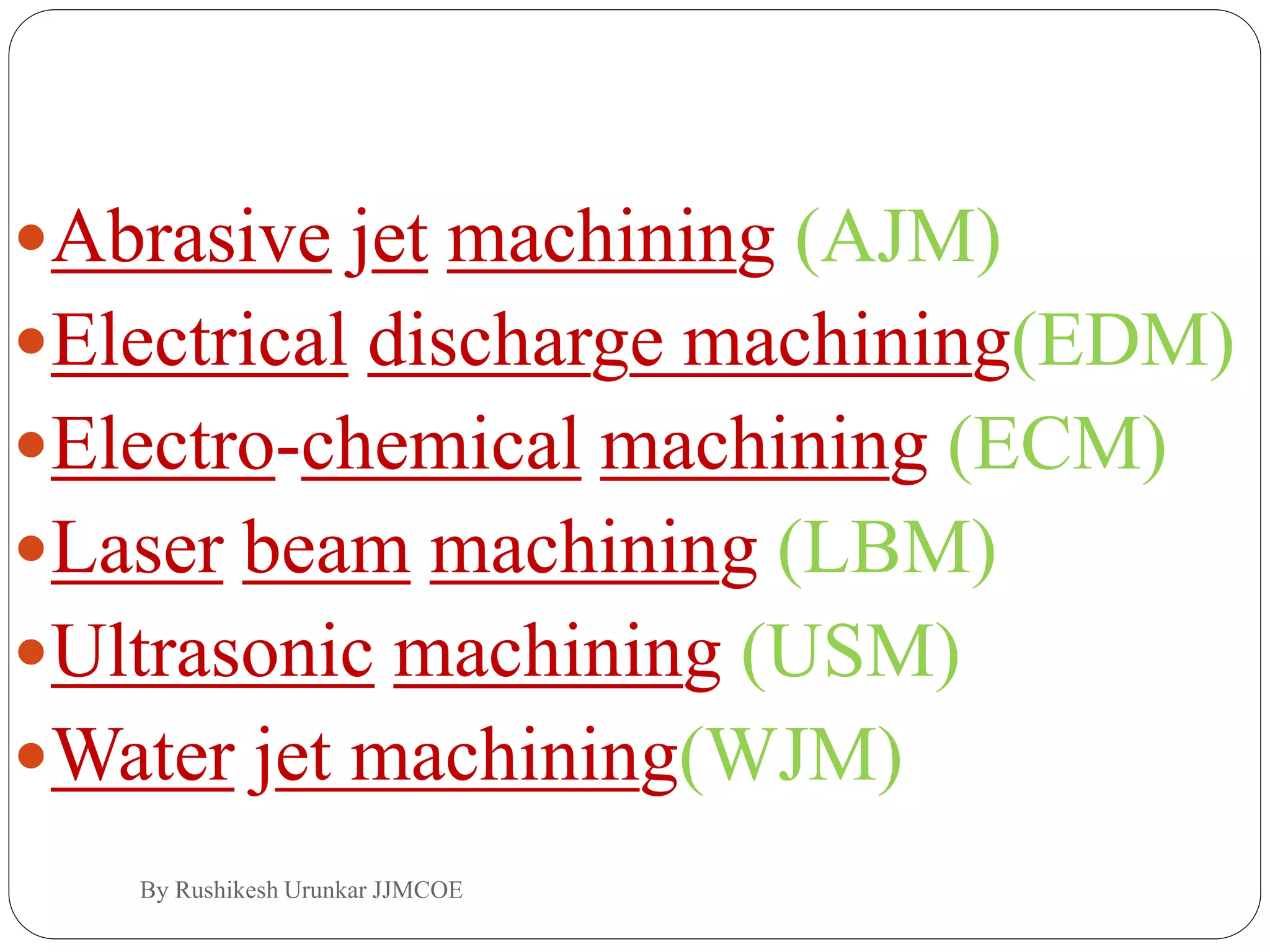
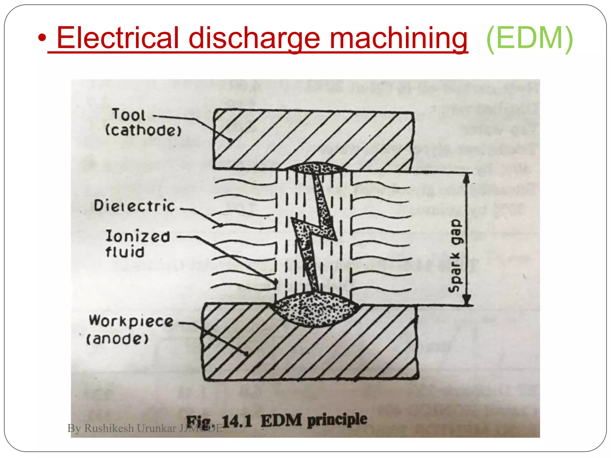
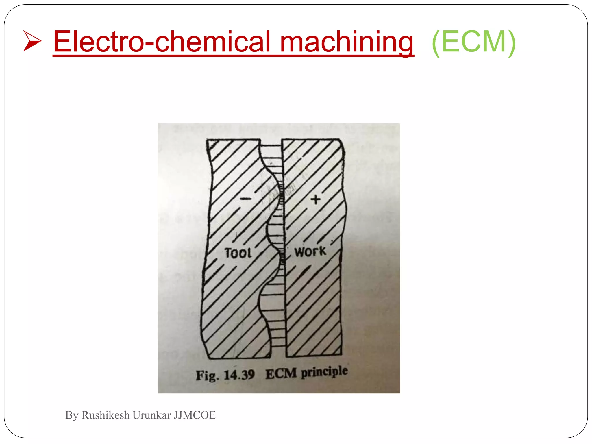
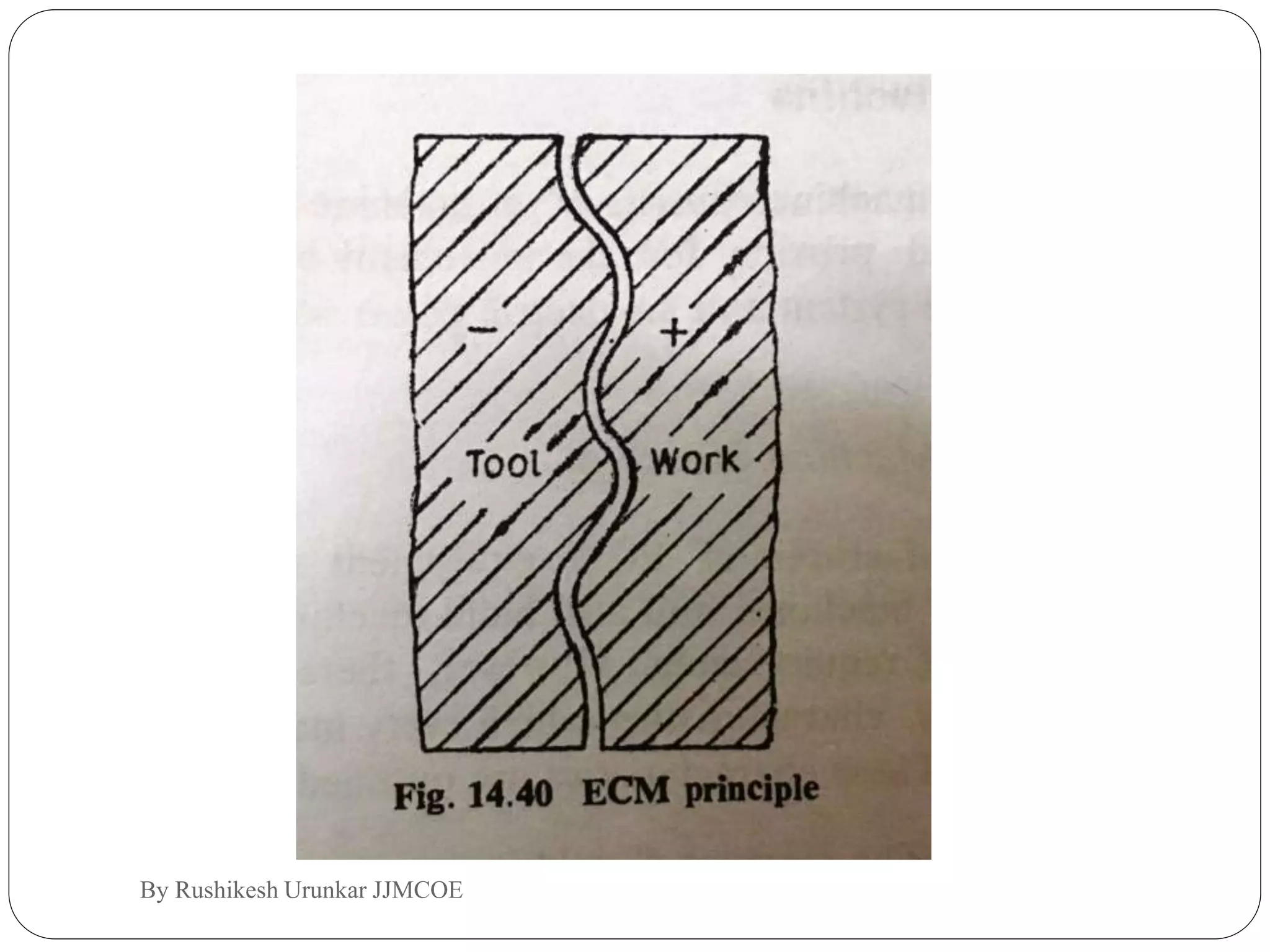
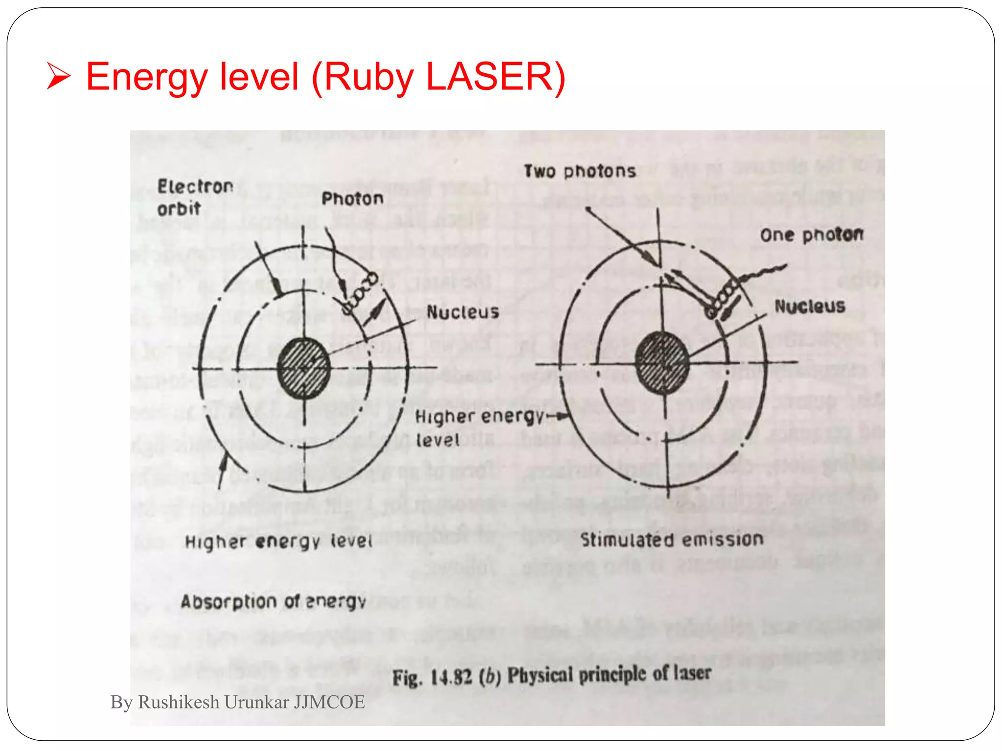
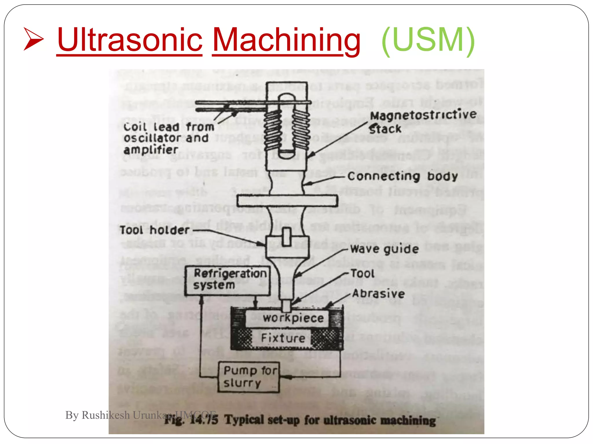
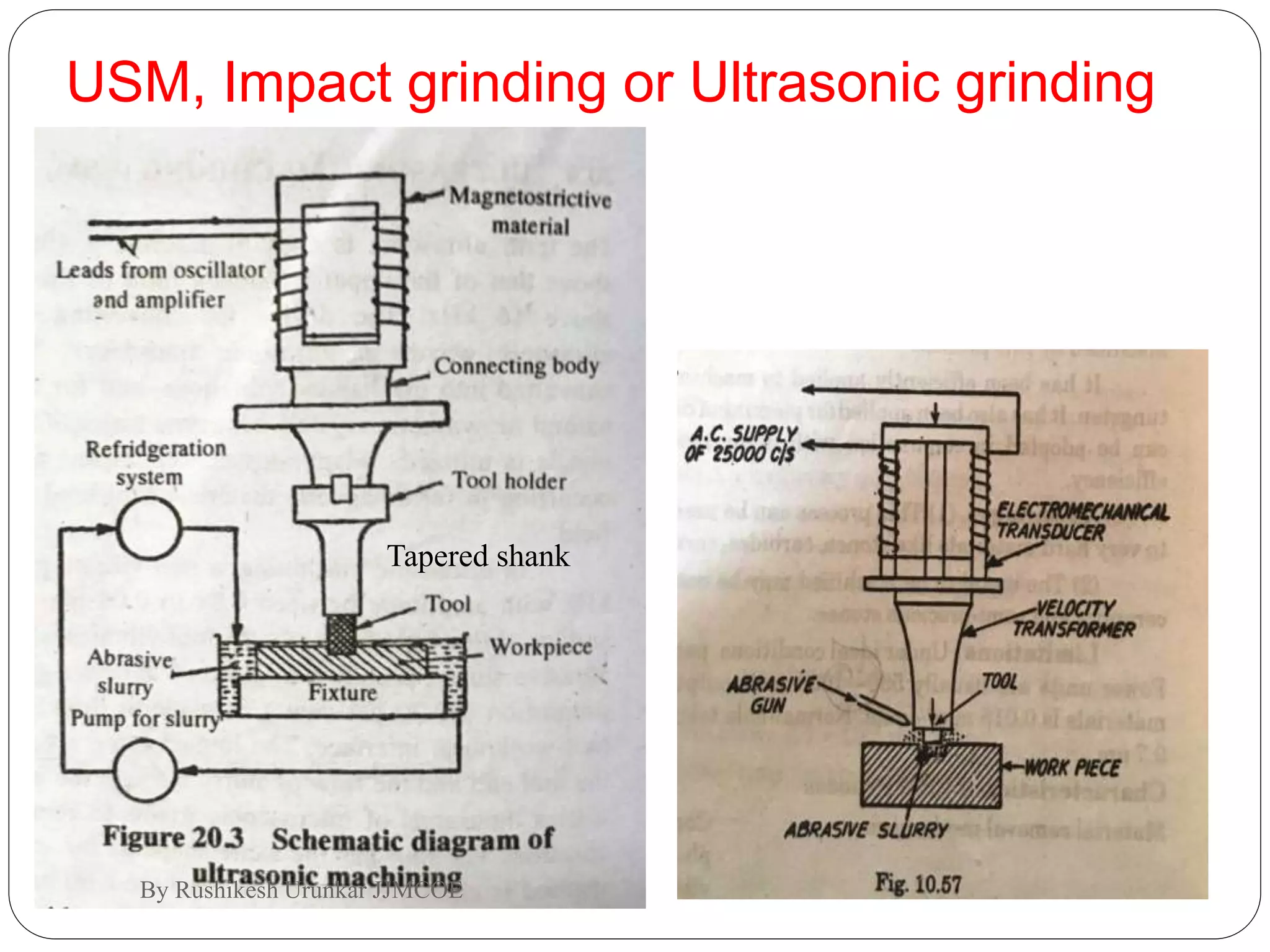
this topic comes under manufacturing engineering or particularly machine tools.it gives brief information on non conventional machining which includes total six no of machines.
High velocity forming involves imparting high kinetic energy to a workpiece by accelerating it to a high velocity before forming it using a die. This allows forming of complex parts from difficult to form alloys. It has advantages over conventional forming like better formability, uniform strains, and lower die costs. However, it requires more energy and skilled personnel. A comparison shows that high velocity forming is suitable for deep drawing, bulged parts, and complex shapes while conventional forming works better for bending, flanged parts, and linear shapes. Plane forming and deep drawing can be done by either method.
This document discusses two types of unconventional metal forming methods: high energy rate forming (HERF) and high velocity forming (HVF). HERF uses energy directly to form metals, while HVF first converts energy to mechanical energy imparting velocity. Explosive forming and electrohydraulic forming are examples of HERF that use explosives or electric sparks to rapidly form sheet metal. Explosive forming can be done via a standoff or contact method. Electrohydraulic forming uses high voltage discharge through water to rapidly form tubular parts. Both techniques can form complex shapes and large parts at high production rates.
This document summarizes the key characteristics and differences between spur gears and helical gears. It discusses how spur gears have straight teeth parallel to the axes, while helical gears have teeth that are curved and helically shaped. Helical gears operate more smoothly and quietly compared to spur gears due to the gradual contact of the teeth. However, helical gears also induce axial thrust on the bearings. The document provides examples of applications for each gear type and concludes with the authors thanking the reader.
The document provides an overview of the metal spinning process. It discusses the history and classification of different metal spinning techniques. The basic metal spinning process involves clamping a metal blank between a spinning mandrel and follower, and using specially designed tools to form the blank into an axially symmetric product while it rotates at high speeds. Key aspects covered include the mechanics of cone spinning, use of multi-pass spinning for small cone angles, mandrel and tool design, lubricants, common spinning machines, advantages over other forming processes, and applications.
This document discusses helical springs and U-clamps. It defines springs and their main uses which include exerting force, providing flexibility, and storing energy. The most common spring materials are discussed along with the types of springs including helical, flat, and special shaped. Helical springs are further broken down into open coil, closed coil, torsion, and spiral varieties. U-clamps are metal clamps used to mount pipes and are made of stainless steel or mild steel for durability.
The document discusses gears and their classification. It defines various gear types including spur gears, helical gears, bevel gears, worm gears, and rack gears. It covers gear terminology such as pressure angle and describes how parameters like pressure angle and center distance affect gear performance and interference. Methods to avoid interference include increasing center distance, tooth modification, and changing the number of teeth. Backlash is also defined as the clearance between mating gear teeth.
Rapid prototyping technologies allow engineers to create physical prototypes of designs prior to full production. The document discusses the rapid prototyping process which involves:
1. Creating a CAD model and converting it to STL format.
2. Slicing the STL file into thin layers and constructing the prototype layer-by-layer using different techniques like stereolithography, selective laser sintering, or fused deposition modeling.
3. Post-processing the prototype by removing supports, cleaning, and finishing the surface.
Specific rapid prototyping methods like stereolithography, selective laser sintering, and fused deposition modeling are described in detail. The document also discusses applications and limitations of rapid
Manufacturing Technology , Bending Process .
Tackles mainly about the definition of Bending process, how does it work, the machines & equipment used to make it work and the application of Bending on manufacturing Industries.
Please Don't forget to Like before you download the presentation.
1. The document discusses various form measurement principles and methods including straightness, flatness, thread measurement, gear measurement, surface finish measurement, and roundness measurement.
2. Thread measurement involves measuring various thread elements like major diameter, minor diameter, pitch, and form using methods such as thread plug gauges, thread wires, and thread micrometers.
3. Gear measurement includes measuring parameters like pitch, lead, backlash, tooth thickness, and errors using equipment such as involute measuring machines, gear tooth vernier calipers, and gear testers.
4. Surface finish is measured using various instruments that analyze surface texture parameters like average roughness, peak-valley height, and form factor.
CAPSTAN AND TURRET LATHES AND DIFFERENCES BY POLAYYA CHINTADAPOLAYYA CHINTADA
The document discusses capstan and turret lathes. It defines a capstan lathe as having a turret mounted on a ram that is mounted on the saddle, allowing the ram to provide feed to the cutting tools. Capstan lathes are lighter and provide limited feed and depth of cut. Turret lathes have the turret directly mounted on the saddle to provide feed, are heavier/more durable, and provide more feed and depth of cut for mass production of large parts. The key difference is the location of the turret - on the ram for capstan lathes and directly on the saddle for turret lathes.
This document discusses design considerations for additive manufacturing (AM) with metals. It outlines that while AM provides design freedom, there are still capabilities and limitations to consider. Key factors for metal AM include minimum feature size due to laser spot diameter, avoiding large overhangs and interior holes that require supports, minimizing supports through feature shape and part orientation, and preventing part distortion from residual stress. The document presents a case study comparing a conventional hydraulic manifold design to designs adapted and purposefully designed for AM, showing increased mass savings as the design leverages more AM capabilities. True design for AM allows for an extremely efficient design that consolidates parts and is self-supporting. Understanding AM characteristics is important for successful design.
The document discusses drilling and boring machines. It describes how drilling machines are used to produce circular holes in workpieces using rotating cutters called drills. Different types of drilling machines are described, including portable drilling machines, sensitive bench drilling machines, upright drilling machines, radial drilling machines, gang drilling machines, turret drilling machines, and deep hole drilling machines. The document also covers topics such as tool nomenclature, drilling operations, tool holding devices, work holding devices, drill types, and reaming.
Rod, wire and tube drawing is a metalworking process where a rod, wire or tube is pulled through a die to reduce its cross-sectional area and increase its length. It involves applying both tensile and compressive forces. Products include wire, rods, and tubes used in applications like electrical wiring, springs and hydraulic tubing. The process offers close dimensional control, lower costs than rolling or extrusion, and can produce very small cross-sections. Lubrication and annealing are important to control work hardening during multiple drawing passes. Dies are commonly made of alloy steels, carbides or diamond to withstand wear from the process.
This presentation provides an overview of worm gears, including their two types (cylindrical and cone), three types of worm gears, common materials used, key terms, how they work to reduce speed and increase torque via a high velocity ratio, common applications, advantages of being self-locking and occupying less space, disadvantages of higher costs and lower efficiency, and areas for further research such as improved lubrication. Worm gears are widely used gear systems for transmitting power between non-intersecting shafts, especially at high velocity ratios.
Bevel gears are used to transmit motion between two intersecting shafts at any angle. The design procedure involves selecting materials, tooth profiles, and module based on requirements and strength calculations. Bevel gears are then designed with the proper diameters, cone distance, and face width. Design is checked for surface and bending stresses. Bevel gears are commonly used in differentials and hand drills to change the direction of rotation. They allow transmission of power between non-parallel shafts but require precise mounting and bearings.
The taylor hobson talysurf surface roughness testervaibhav tailor
This instrument measures surface roughness using a stylus attached to an armature. Variations in the surface profile are sensed by the stylus and cause the gap between the armature and an E-shaped arm to vary, modulating the AC current in a coil. This modulation is demodulated so the output is directly proportional to the vertical displacement of the stylus, allowing a recorder to produce a record of the surface roughness. The instrument provides a more rapid and accurate measurement of surface roughness compared to the Tomlinson surface tester.
The document defines key terms related to stress, strain, and material properties including stress, strain, tensile stress, compressive stress, Young's modulus, shear stress, shear modulus, bearing stress, and thermal stresses. It also discusses stress-strain diagrams, working stress, factor of safety, stresses in composite bars, and provides examples of calculations and applications for various material properties.
This presentation provides an overview of worm gears. It defines worm gears as gears that can transmit power at high velocity ratios between non-intersecting shafts, often at right angles. There are two types of worms: cylindrical and cone. The three main types of worm gears are straight face, hobbed straight face, and concave face. Worm gears are commonly used to reduce speed and increase torque in applications like lifts, conveyors, and presses. While they provide advantages like self-locking and space efficiency, they also have disadvantages like higher power losses and lower transmission efficiency compared to other gear types.
Explosive Forming is a manufacturing technique that uses explosions to force metal into dies and molds.
The explosives are typically either detonated underwater or in direct contact with the materials.
The technique is useful for short production runs of conventionally difficult-to-manufacture parts.
In Explosive Forming a punch or diaphragm in conventional forming is replaced by an explosive charge.
Chemical energy from the explosives is used to generate shockwaves through a medium (mostly water), which are directed to deform the workpiece at very high velocities.
The document discusses surface finish and roughness measurement. It defines terms like surface texture, roughness, waviness, and provides explanations of different measurement methods and parameters like Ra, Rz, and Rmax. Measurement methods covered include comparison methods, profilometers, and instruments like the Taylor-Hobson Talysurf that can numerically analyze surface roughness.
This document provides an overview of different types of gears including their key components and terminology. It discusses common gear types like spur gears, helical gears, bevel gears, and worm gears. For each type it provides examples of advantages and disadvantages as well as typical applications. The document also discusses gear materials and common modes of gear failure such as scoring, wear, pitting, plastic flow, and tooth fracture.
Advantages and limitation of non traditional machiningMrunal Mohadikar
The document provides an overview of several non-traditional machining processes including Electrical Discharge Machining (EDM), Electrochemical Machining (ECM), Ultrasonic Machining (USM), Laser Beam Machining (LBM), Water Jet Cutting, and Abrasive Water Jet Cutting. For each process, the document discusses the basic technique, key advantages such as ability to machine hard materials and produce complex shapes, and limitations such as low material removal rates or inability to machine non-conductive materials. The document serves to educate readers on alternative manufacturing methods beyond traditional cutting tools and their various applications and constraints.
Mig welding process is semi automatic when used for manual welding . It can be used in welding automation systems for high quality welds and high productivity.
This document discusses power hacksaws, which are used to cut large pieces of metal like steel that would be difficult to cut by hand. It describes the main parts of a power hacksaw, including the reciprocating frame that moves the saw blade back and forth to cut the metal. The document outlines different types of power hacksaw drives and feed mechanisms that control the downward pressure of the blade. It provides guidance on operating a power hacksaw safely, including using coolant fluid to lubricate the blade and prevent overheating.
The document discusses various unconventional machining processes. It begins with introducing that unconventional machining uses indirect energy like sparks, heat or chemicals rather than direct contact between a tool and workpiece. It then covers different unconventional processes like EDM, laser beam machining, electrochemical machining and their characteristics. The document categorizes unconventional machining processes and provides details on processes like chemical machining, electrochemical grinding and ultrasonic machining. It concludes with discussing advantages and disadvantages of non-conventional machining.
Unit 4 discusses several non-traditional machining processes including abrasive jet machining. Abrasive jet machining involves using a high-velocity jet of abrasive particles carried by a carrier gas to remove material from a workpiece. Key aspects of the process are that abrasive particles around 50 micrometers are accelerated to 200 meters per second by compressed air or gas and directed at the workpiece by a nozzle. Process parameters that can be controlled include the abrasive type and size, carrier gas properties, abrasive jet velocity and flow rate, standoff distance, and impingement angle. Abrasive jet machining is suitable for drilling intricate shapes in hard and brittle materials.
Electrical discharge machining (EDM) is a non-traditional machining process that uses electric sparks to erode metal. In EDM, a potential difference is created between an electrode tool and conductive workpiece, causing electric sparks that remove small amounts of metal. Key advantages of EDM include the ability to machine very hard materials and complex shapes. Main applications are for molds, dies, and parts requiring close tolerances that would be difficult with traditional cutting tools. The document discusses the history, process, equipment, parameters, advantages, and limitations of EDM.
The document discusses abrasive waterjet machining (AWJM), a non-conventional machining process. It provides a brief history of AWJM, describing how abrasives were added to waterjets in the 1970s to allow cutting of harder materials. The key components of an AWJM system are described, including water reservoirs, intensifier pumps to generate ultra-high water pressures, multi-axis motion systems, and abrasive-fed nozzles. Advantages are clean cutting with minimal heat impact and ability to cut a wide range of materials efficiently. Disadvantages include high operating costs for hard materials and inability to cut very thick parts. The document outlines applications and provides comparisons to other non-conventional machining methods.
This document discusses electric discharge machining (EDM), a non-conventional machining process that removes metal using electric sparks. EDM involves removing material through electric sparking between an electrode tool and a metal workpiece separated by a dielectric fluid. There are two main types of EDM: wire-cut EDM, which uses a continuously moving wire as the electrode, and ram/sinker EDM, which uses a solid electrode. EDM can machine very hard metals, achieve a high degree of accuracy and precision, and create complex shapes without mechanical forces.
The document discusses non-conventional machining processes, specifically electric discharge machining (EDM). EDM uses electric sparks to thermally remove metal from a workpiece without contact between the tool and workpiece. There are several types of EDM including ram EDM, wire EDM, and small hole EDM. EDM can machine hard materials, achieve high accuracy and surface finish, and is widely used for dies, aerospace parts, and medical devices. While offering advantages over traditional machining, EDM also has limitations such as low material removal rates and electrode wear.
This document discusses various methods for improving material removal rate (MRR) in electrical discharge machining (EDM). It explains that EDM uses thermoelectric energy from electric sparks to remove material from conductive workpieces. MRR can be improved through electrode design and geometry, controlling process parameters like voltage, current, and pulse duration, using EDM variations with ultrasonic vibration or rotation, mixing powders into the dielectric fluid, using gas as the dielectric medium, and techniques like multi-spark EDM. Overall, MRR is an important performance measure that relies on empirical methods and requires further research due to the complex interrelationship between electrical and non-electrical parameters in the stochastic EDM process.
The document provides information on the fundamentals and operating principles of electrical discharge machining (EDM). It discusses the history and development of EDM, the preparation and phases of discharge, voltage-current characteristics, theories of material removal, debris generation and morphology, process parameters that affect performance, and components and schematics of EDM systems.
Eectrochemical Grinding by Himanshu VaidHimanshu Vaid
Electro chemical grinding is a process that involves an electrochemical reaction to remove material. It can grind intricate shapes and contours to a high precision. The document expresses gratitude to the reader for their time.
Abrasive jet machining is an unconventional machining process that uses a high-velocity stream of abrasive particles suspended in a gas to remove material through erosion. It can machine hard and brittle materials that cannot be cut through conventional processes. The process involves mixing abrasive particles with a pressurized gas and passing them through a nozzle to erode away the workpiece material. It provides advantages like ability to machine heat-sensitive materials without damaging them and capability to cut intricate holes, but has low material removal rates and accuracy issues due to stray cutting.
The document provides information about wire electrical discharge machining (EDM). It discusses how wire EDM works by using a thin wire fed through the workpiece to cut complex shapes. The document outlines the objectives, scope, safety precautions, and standard operating procedure for a project using a Mitsubishi wire EDM machine to cut a mild steel workpiece. It also analyzes the output part and discusses advantages and disadvantages of wire EDM.
Electrical discharge machining (EDM) is a non-traditional machining process that uses electrical sparks to remove metal. The document discusses the history and development of EDM, including key components like the electrode, workpiece, dielectric fluid, and power supply. It describes the basic EDM process and different EDM methods like conventional EDM, wire EDM, and hole drilling EDM. The document also covers EDM applications, innovations like dry EDM and powder-mixed EDM, and concludes with a list of references.
The document describes the electrical discharge machining (EDM) process. EDM involves using electrical sparks to erode material from a conductive workpiece. A tool shaped to the desired cavity or hole acts as an electrode and is placed near the workpiece in a dielectric fluid. High-frequency pulses of voltage are applied, causing sparks that melt and evaporate small amounts of material. The process is repeated until the cavity is shaped. Key aspects of EDM include the dielectric fluid, gap size, electrode material, and operating parameters which control the machining rate and surface finish.
Electric discharge machining (EDM) is a machining process that uses electrical sparks to erode metals. It works by maintaining a precise gap between an electrode tool and a metal workpiece submerged in a dielectric fluid. Repeated electrical sparks are generated to melt and vaporize small amounts of metal from both the tool and workpiece, allowing complex and hard-to-machine shapes to be produced. EDM can machine metals regardless of hardness and without mechanical force, giving it advantages over traditional machining methods for difficult-to-cut materials.
This document discusses electrochemical machining (ECM), which is a non-traditional machining process that involves removing metal by electrolytic dissolution. ECM works by placing a conductive workpiece and shaped electrode in an electrolytic fluid and running a low-voltage, high-amperage current between them, causing metal ions from the workpiece to dissolve into the fluid. The document covers the history, working principles, components, advantages, disadvantages, applications, and products of ECM.
Abrasive jet machining uses a high-pressure stream of abrasive particles suspended in a liquid to erode material from a workpiece. It involves a pump, mixing tube, nozzle, and motion system to direct the abrasive jet. Key components include an abrasive delivery system to store and feed abrasive, a control system to vary the feed rate, and a precision motion table. The process provides fast setup, requires no start holes, uses a single tool, and generates no heat in the workpiece. However, removal rates are low and accuracy can decrease with deeper cuts.
Electro-chemical machining (ECM) is a non-traditional machining process that removes metal by dissolving it in an electrolyte with the use of electric current. In ECM, the workpiece acts as an anode and is dissolved by the electrolyte, while a tool with the desired shape acts as a cathode. Key factors in ECM include the electrolyte, which carries current and removes dissolved material, the tool and workpiece materials, and a DC power supply. ECM can machine hard metals and complex shapes with high accuracy and no tool wear. Common applications of ECM include machining turbine blades, aerospace components, and other difficult-to-machine metals.
Nontraditional machining processes remove material using mechanical, thermal, electrical, or chemical energy instead of sharp cutting tools. They were developed after WWII to machine materials that cannot be cut conventionally like hard metals. Examples are ultrasonic machining (uses abrasives in slurry), water jet cutting (high pressure water), electric discharge machining (material removal by electric sparks), and laser beam machining (uses a laser). Nontraditional processes are used for complex parts, hard materials, and when traditional machining causes undesirable effects like high temperatures or residual stresses.
This document discusses nontraditional manufacturing processes. It provides an overview of ultrasonic machining (USM), describing the process, material removal mechanism, advantages, disadvantages, and applications. It also summarizes waterjet machining (WJM) and abrasive waterjet machining (AWJM), explaining the principles, advantages, disadvantages, and applications of these processes. Finally, it briefly introduces abrasive jet machining (AJM), describing the basic process and its uses.
The document discusses various non-conventional machining processes that remove material using means other than traditional cutting tools. It describes abrasive jet machining, ultrasonic machining, waterjet cutting, electrochemical machining, electrochemical grinding, electrodischarge machining, laser beam machining, and chemical machining. These alternative processes can machine hard or complex materials and features that cannot be done with conventional machining. The document provides details on the mechanisms, parameters, advantages, and applications of various non-traditional machining methods.
The document discusses non-conventional machining processes. It begins by distinguishing between conventional machining processes, which use hard cutting tools to remove material, and non-conventional processes, which use other energies like mechanical, thermal, electrical, or chemical. Non-conventional processes are then classified based on the type of energy used, including mechanical, electrochemical, electro-thermal, and chemical processes. Examples of specific non-conventional machining techniques are provided within each classification.
Mechanical processes
Machining and grinding (will be covered in later classes)
Shearing, blanking, and punching (sheet metalworking operations)
Ultrasonic machining (USM)
Water jet cutting (WJC or hydro-jet)
Abrasive water jet cutting (AWJC or abrasive hydro-jet)
The document discusses various unconventional machining processes. It begins by introducing unconventional machining and its advantages over conventional machining such as the ability to machine very hard materials and complex shapes. It then categorizes unconventional machining processes into mechanical, electro-thermal, and chemical/electrochemical processes. Several specific unconventional processes are described in detail, including electrical discharge machining, electrochemical machining, laser beam machining, water jet machining, and ultrasonic machining. The document provides an overview of the basic techniques, applications, and advantages of various unconventional machining processes.
The document discusses various thermal energy-based material removal techniques, focusing on electrical discharge machining (EDM) and laser beam machining (LBM). It provides details on the EDM and LBM processes, including how they work, common applications, advantages, and limitations. EDM uses electric sparks to melt and vaporize material, while LBM uses a focused laser beam. Both processes precisely shape materials by thermal heating without mechanical forces.
This document discusses various nontraditional machining and thermal cutting processes. It begins by defining these processes as those that remove material using mechanical, thermal, electrical, or chemical energy without a conventional cutting tool. These alternative processes are important for machining new metals and non-metals, producing complex geometries, and avoiding surface damage from traditional methods. The document then groups and describes various nontraditional processes including mechanical (ultrasonic machining, water jet cutting), electrochemical (electrochemical machining), thermal (electric discharge machining, laser beam machining), and chemical (chemical milling) processes.
This document provides an introduction to non-conventional machining processes. It discusses how these processes use indirect energy like sparks, lasers, heat, or chemicals rather than direct contact between a tool and workpiece. Some key non-conventional machining processes described include electrical discharge machining, wire EDM, laser beam machining, electron beam machining, water jet machining, abrasive jet machining, ultrasonic machining, electrochemical machining, and electrochemical grinding. Advantages of these processes include high accuracy, less wear, longer tool life, and reduced environmental hazards compared to conventional machining.
This document discusses various non-traditional machining (NTM) processes, including their need, classification, parameters, advantages, limitations, and applications. It covers mechanical processes like ultrasonic machining, abrasive jet machining, and water jet machining. It also discusses chemical/electrochemical processes like electrochemical machining, thermal/electrothermal processes like laser beam machining and plasma arc machining, and electrical discharge machining. Each process is explained along with diagrams and tables of parameters for different materials.
The document discusses various advanced manufacturing processes that use thermal energy or electrical discharges to remove material from a workpiece. It focuses on electrical discharge machining (EDM) and wire EDM. EDM works by sparking electrical discharges between an electrode and workpiece submerged in dielectric fluid to erode away material. Key advantages of EDM are its ability to machine hard metals and create complex shapes. The document also covers laser beam machining which uses a focused laser beam to melt, vaporize, or ablate material from the workpiece.
This document provides an overview of unconventional machining processes. It begins with an introduction to conventional machining processes and then discusses the need for unconventional processes to machine advanced materials. The document categorizes unconventional processes as mechanical, electrical, chemical/electrochemical, or thermal based. Specific unconventional processes like ultrasonic machining and abrasive water jet cutting are then described in more detail.
This document provides an overview of unconventional machining processes. It begins by defining conventional machining and its limitations in machining complex geometries and hard materials. Unconventional machining uses indirect energy sources like sparks, heat, or chemicals instead of direct tool contact. The document then discusses various unconventional processes like EDM, laser beam machining, water jet machining, and their characteristics. It classifies unconventional processes and provides details on electrochemical machining, electrochemical grinding, and ultrasonic machining. In closing, it acknowledges the development of these nontraditional techniques for precision manufacturing applications.
Abrasive jet machining uses abrasive particles suspended in a gas or liquid to machine materials through erosion. Key points include:
- Abrasive particles like aluminum oxide or silicon carbide are accelerated to high velocities and directed at a workpiece to erode away material.
- Process parameters like abrasive size and flow rate influence the material removal rate, with larger abrasives providing higher removal.
- Applications include cutting, cleaning, etching, and polishing of brittle materials like ceramics, concrete, and composites that are difficult to machine with traditional methods.
- While allowing machining of hard materials, abrasive jet machining has low material removal rates and issues with stray cutting
Abrasive jet machining uses abrasive particles suspended in a gas or liquid to machine materials. It can cut harder materials like ceramics and composites faster than conventional machining. The abrasive particles impact the workpiece at high velocities of 150-300 m/s, removing material through brittle fracture. Larger abrasive grain sizes and higher flow rates increase the material removal rate. Common abrasives include aluminum oxide, silicon carbide, and magnesium carbonate.
The document discusses various thermal energy-based material removal techniques, including electrical discharge machining (EDM) and laser beam machining (LBM). It provides details on the EDM process, including how it works using electric sparks to erode metals. Wire EDM and micro EDM are also examined. The document then covers the LBM process, the types of lasers used for different applications like cutting, drilling, and marking. It discusses key laser beam parameters such as beam waist, intensity, and depth of focus. In summary, the document provides an in-depth overview of EDM and LBM processes for removing material using thermal energy.
This document discusses advanced machining processes, which utilize chemical, electrical, or high-energy beams to machine materials that cannot be processed through traditional machining methods. It describes 10 common types of advanced machining, including chemical machining, electrochemical machining, electrical discharge machining, laser beam machining, electron beam machining, plasma arc cutting, ultrasonic machining, water jet machining, abrasive jet machining, and nanofabrication methods. The document explains the need for these advanced processes and provides examples of typical parts machined through these methods.
CHINA’S GEO-ECONOMIC OUTREACH IN CENTRAL ASIAN COUNTRIES AND FUTURE PROSPECTjpsjournal1
The rivalry between prominent international actors for dominance over Central Asia's hydrocarbon
reserves and the ancient silk trade route, along with China's diplomatic endeavours in the area, has been
referred to as the "New Great Game." This research centres on the power struggle, considering
geopolitical, geostrategic, and geoeconomic variables. Topics including trade, political hegemony, oil
politics, and conventional and nontraditional security are all explored and explained by the researcher.
Using Mackinder's Heartland, Spykman Rimland, and Hegemonic Stability theories, examines China's role
in Central Asia. This study adheres to the empirical epistemological method and has taken care of
objectivity. This study analyze primary and secondary research documents critically to elaborate role of
china’s geo economic outreach in central Asian countries and its future prospect. China is thriving in trade,
pipeline politics, and winning states, according to this study, thanks to important instruments like the
Shanghai Cooperation Organisation and the Belt and Road Economic Initiative. According to this study,
China is seeing significant success in commerce, pipeline politics, and gaining influence on other
governments. This success may be attributed to the effective utilisation of key tools such as the Shanghai
Cooperation Organisation and the Belt and Road Economic Initiative.
Redefining brain tumor segmentation: a cutting-edge convolutional neural netw...IJECEIAES
Medical image analysis has witnessed significant advancements with deep learning techniques. In the domain of brain tumor segmentation, the ability to
precisely delineate tumor boundaries from magnetic resonance imaging (MRI)
scans holds profound implications for diagnosis. This study presents an ensemble convolutional neural network (CNN) with transfer learning, integrating
the state-of-the-art Deeplabv3+ architecture with the ResNet18 backbone. The
model is rigorously trained and evaluated, exhibiting remarkable performance
metrics, including an impressive global accuracy of 99.286%, a high-class accuracy of 82.191%, a mean intersection over union (IoU) of 79.900%, a weighted
IoU of 98.620%, and a Boundary F1 (BF) score of 83.303%. Notably, a detailed comparative analysis with existing methods showcases the superiority of
our proposed model. These findings underscore the model’s competence in precise brain tumor localization, underscoring its potential to revolutionize medical
image analysis and enhance healthcare outcomes. This research paves the way
for future exploration and optimization of advanced CNN models in medical
imaging, emphasizing addressing false positives and resource efficiency.
Electric vehicle and photovoltaic advanced roles in enhancing the financial p...IJECEIAES
Climate change's impact on the planet forced the United Nations and governments to promote green energies and electric transportation. The deployments of photovoltaic (PV) and electric vehicle (EV) systems gained stronger momentum due to their numerous advantages over fossil fuel types. The advantages go beyond sustainability to reach financial support and stability. The work in this paper introduces the hybrid system between PV and EV to support industrial and commercial plants. This paper covers the theoretical framework of the proposed hybrid system including the required equation to complete the cost analysis when PV and EV are present. In addition, the proposed design diagram which sets the priorities and requirements of the system is presented. The proposed approach allows setup to advance their power stability, especially during power outages. The presented information supports researchers and plant owners to complete the necessary analysis while promoting the deployment of clean energy. The result of a case study that represents a dairy milk farmer supports the theoretical works and highlights its advanced benefits to existing plants. The short return on investment of the proposed approach supports the paper's novelty approach for the sustainable electrical system. In addition, the proposed system allows for an isolated power setup without the need for a transmission line which enhances the safety of the electrical network
Advanced control scheme of doubly fed induction generator for wind turbine us...IJECEIAES
This paper describes a speed control device for generating electrical energy on an electricity network based on the doubly fed induction generator (DFIG) used for wind power conversion systems. At first, a double-fed induction generator model was constructed. A control law is formulated to govern the flow of energy between the stator of a DFIG and the energy network using three types of controllers: proportional integral (PI), sliding mode controller (SMC) and second order sliding mode controller (SOSMC). Their different results in terms of power reference tracking, reaction to unexpected speed fluctuations, sensitivity to perturbations, and resilience against machine parameter alterations are compared. MATLAB/Simulink was used to conduct the simulations for the preceding study. Multiple simulations have shown very satisfying results, and the investigations demonstrate the efficacy and power-enhancing capabilities of the suggested control system.
Understanding Inductive Bias in Machine LearningSUTEJAS
This presentation explores the concept of inductive bias in machine learning. It explains how algorithms come with built-in assumptions and preferences that guide the learning process. You'll learn about the different types of inductive bias and how they can impact the performance and generalizability of machine learning models.
The presentation also covers the positive and negative aspects of inductive bias, along with strategies for mitigating potential drawbacks. We'll explore examples of how bias manifests in algorithms like neural networks and decision trees.
By understanding inductive bias, you can gain valuable insights into how machine learning models work and make informed decisions when building and deploying them.
KuberTENes Birthday Bash Guadalajara - K8sGPT first impressionsVictor Morales
K8sGPT is a tool that analyzes and diagnoses Kubernetes clusters. This presentation was used to share the requirements and dependencies to deploy K8sGPT in a local environment.
International Conference on NLP, Artificial Intelligence, Machine Learning an...gerogepatton
International Conference on NLP, Artificial Intelligence, Machine Learning and Applications (NLAIM 2024) offers a premier global platform for exchanging insights and findings in the theory, methodology, and applications of NLP, Artificial Intelligence, Machine Learning, and their applications. The conference seeks substantial contributions across all key domains of NLP, Artificial Intelligence, Machine Learning, and their practical applications, aiming to foster both theoretical advancements and real-world implementations. With a focus on facilitating collaboration between researchers and practitioners from academia and industry, the conference serves as a nexus for sharing the latest developments in the field.
Harnessing WebAssembly for Real-time Stateless Streaming PipelinesChristina Lin
Traditionally, dealing with real-time data pipelines has involved significant overhead, even for straightforward tasks like data transformation or masking. However, in this talk, we’ll venture into the dynamic realm of WebAssembly (WASM) and discover how it can revolutionize the creation of stateless streaming pipelines within a Kafka (Redpanda) broker. These pipelines are adept at managing low-latency, high-data-volume scenarios.
The CBC machine is a common diagnostic tool used by doctors to measure a patient's red blood cell count, white blood cell count and platelet count. The machine uses a small sample of the patient's blood, which is then placed into special tubes and analyzed. The results of the analysis are then displayed on a screen for the doctor to review. The CBC machine is an important tool for diagnosing various conditions, such as anemia, infection and leukemia. It can also help to monitor a patient's response to treatment.
3. • Abrasive jet machining (AJM)
By Rushikesh Urunkar JJMCOE
4. Abrasive materials
Aluminum oxide
Silicon carbide
Dolomite (calcium magnesium carbonate)
Sodium bicarbonate
Glass beads
Size of abrasive
Around 25µm
Medium
Air or co2
Velocity -150 to 300m/sec
Pressure 2 to 8kg/cm²
Nozzle – WC with orifice .05-0.2mm³
Nozzle tip distance 0.25-15mm
By Rushikesh Urunkar JJMCOE
5. Work material
Hard and brittle materials like glass, ceramics, mica etc
Machining operations
Drilling, cutting, debarring, cleaning
By Rushikesh Urunkar JJMCOE
8. Advantages of AJM
Ability to cut intricate hole shapes in hard and brittle materials
Ability to cut fragile and heat sensitive materials without damage
because there is no heating of working surface
Low capital cost
Machining of semiconductors
Limitations of AJM
Slow material removal rate
Low accuracy (0.1mm) due to stray cutting (taper effect)
Embedding of the abrasive in the w/p surface may occur while
m/cing softer materials
Abrasive powder can not be refuse
unwanted waste material, especially material that
is regularly thrown away from a house, factory, etc.:By Rushikesh Urunkar JJMCOE
9. Taper is also a problem
Abrasive powder can not be reused
Machining accuracy is relatively poorer
It is not suitable for machining ductile materials
There is always a danger of abrasive particles getting
embedded in the work material, hence cleaning needs to
be necessarily done after the operation
By Rushikesh Urunkar JJMCOE
10. • Applications :
Cutting slots, thin sections, contouring, drilling, deburring
and for producing intricate shapes in hard and brittle
materials
It is often used for cleaning and polishing of plastics ,
nylon and teflon components
Frosting of the interior surface of the glass tubes
Etching of markings on glass cylinders etc
Machining of semiconductors
By Rushikesh Urunkar JJMCOE
13. Small Spark gap is about 0.01-0.50mm and spark
frequency 200-500 KHz
The electric current is varied within a wide range from .5
to 400amp at 40-300V dc
The dielectric fluid is pumped through the tool or w/p at a
pressure of 2kg/cm²
Material removal rate(max) 5000mm³/min
Specific power consumption 2-10W/mm³/min
By Rushikesh Urunkar JJMCOE
14. Tool material
Brass, copper, graphite, copper tungsten, tungsten carbide
Dielectric fluid
Hydrocarbon oils, kerosene liquid paraffin, silicon oils,
aqueous solution of ethylene glycol
Materials that can be machined
All conducting metals and alloys
By Rushikesh Urunkar JJMCOE
15. Advantages
The process can be applied to all electrically conducting
metals and alloys irrespective of their melting points,
hardness, toughness or brittleness
Time of machining is less than conventional machining
No mechanical stress is present in the process
Fragile and slender w/ps can be machined without
distortion
Hard and corrosion resistant surfaces, essentially needed
for die making, can be developed
By Rushikesh Urunkar JJMCOE
16. Limitations
Machining times are too long
Excessive tool wear
High specific power consumption
Machining heats the w/p considerably and hence causes
change in surface and metallurgical properties
Profile m/cing of complex contours is not possible at
required tolerances
By Rushikesh Urunkar JJMCOE
17. Applications
The EDM provides economic advantage for making
stamping tools, wire drawing and extrusion dies, header
dies, forging dies, intricate mould cavities etc
It has been extremely used for m/cing of exotic materials
used in aerospace industry, refractory metal, hard carbide
and hardenable steels
Typical EDM applications include
fine cutting with thread shaped electrode (wire cutting
EDM)
Drilling of micro-holes
Thread cutting
Helical profile milling
Curved hole drilling
By Rushikesh Urunkar JJMCOE
20. ECM is the controlled removal of metal by anodic
dissolution in an electrolytic medium in which the w/p is
the anode and a shaped tool or electrode is the cathode
Tool material
Cupper, brass or steel
Power supply
Constant voltage DC supply
Voltage 5-30V dc
Current 50-40000 Amp
By Rushikesh Urunkar JJMCOE
21. Electrolyte
Sodium chloride (common salt)
Sodium nitrate
Material removal rate
1600mm³/min
Specific power consumption
7 W/mm³/min (around 150 times more in comparison to
conventional methods )
By Rushikesh Urunkar JJMCOE
22. Advantages of ECM
The machined work surface is free of stresses
Burr- free surface
Reduced tool wear
No cutting forces are involved in the process
No thermal damage
Used for machining difficult to machine materials and
complex shaped parts
Any good electrically conducting material can be
machined
High surface finish of order of 0.1 to 2.0 microns
Very thin sections, such as sheet metals can be easily
m/ned without any damage or distortion
By Rushikesh Urunkar JJMCOE
23. Disadvantages of ECM
Non-conducting materials can not be machined
high specific power consumption
High initial and working cost
Large floor space is required
Designing and fabrication of tools is relatively more difficult
Extremely fine corner radii, say less than 0.2mm, can not be
produce
Specially designed fixtures are required to hold the w/p in
position, because it may be displaced due to the pressure of the
inflowing electrolyte
Corrosion and rusting of w/p, m/c tool, fixture etc by
electrolyte is a constant menance
By Rushikesh Urunkar JJMCOE
24. Applications
Machining of hard to machine and heat resistant materials
Machining of blind holes and pockets, such as in forging
dies
Machining of complicated profiles, such as of jet engine
blades, turbine blades, turbine wheels etc
Drilling small deep holes, such as in nozzle
Machining of cavities and holes of irregular shapes
Deburring of parts
By Rushikesh Urunkar JJMCOE
26. Laser Beam Machining (LBM)
LBM – is a machining process in which the work material
is melted and vaporized by means of an intense,
monochromatic beam of light called the laser
The heat produced in the small area where the laser beam
strikes can melt almost any of the known material
Light Amplification by Stimulated Emission of Radiation
By Rushikesh Urunkar JJMCOE
31. Material removal technique
Heating, melting and vaporization
Tool material
Laser beams in wavelength range of 0.4-0.6 µm
Power density
As high as 107 W/mm²
Output energy of laser and its pulse duration
20J, 1milli second
Peak power
20 KW
Specific power consumption
1000 W/mm³/min
By Rushikesh Urunkar JJMCOE
32. Material removal rate
5mm³/min
Material of work piece
All materials except those with high thermal conductivity
and high reflectivity
By Rushikesh Urunkar JJMCOE
33. Materials :
Almost all materials can be cut/drilled with laser (steel
and steel alloys(including those coated with lead, tin, zinc,
nickel, paint or plastic), titanium, tantalum, nickel)
Non metals which can be cut are – pvc, reinforced plastic,
leather, wood, rubber, wool and cotton,
Inorganic materials like glass, ceramics, asbestos, mica,
stone, alumina and graphite can also be cut or drilled
Dynamic balancing of precision rotating components,
such as of watches
By Rushikesh Urunkar JJMCOE
34. Applications
Machining very small holes and cutting complex
profiles in thin, hard material like ceramics and
tungsten.
Application includes sheet metal trimming, blanking
and resistor trimming
Drilling micro holes (up to 250µm)
Cutting or engraving patterns on thin films
The laser beam is effectively used in welding and heat
treatment of material
By Rushikesh Urunkar JJMCOE
36. There is direct contact b/w tool (laser) and w/p
Machining of any material including non-metals is possible,
irrespective of their hardness and brittleness
Welding, drilling and cutting of areas not readily accessible
are possible
There is no tool wear problem
Soft materials like rubber and plastics can m/cned
Extremely small holes can be m/cned i.e drilling micro holes
(up to 250 µm)
Cutting very narrow slots
can be effectively used for welding of dissimilar metal as well
Advantages :
By Rushikesh Urunkar JJMCOE
37. High capital investment needed
Highly skilled operator are needed
Very large power consumption
Low material removal rate
The process is limited to thin sheet plates(depth limitation)
and where a very small amount of metal removal is
involved
Can not be effectively used to m/c highly heat conductive
and reflective materials
The machined holes are not round and straight
Certain materials like fiber-glass reinforced materials,
phenolics, vinyls etc. cannot be worked by laser as these
materials burn, char and bubble
Disadvantages :
By Rushikesh Urunkar JJMCOE
38. Life of the flash lamp is short
Effectively safety procedures are required
By Rushikesh Urunkar JJMCOE
40. USM, Impact grinding or Ultrasonic grinding
Tapered shank
By Rushikesh Urunkar JJMCOE
41. Material removal mechanism :
complex mechanism involving both fracture and plastic
deformation by impact of grains due to vibrating tool
Tool material :
Soft steel (generally used), monel metal or stainless steel
Monel is a group of nickel alloys, primarily composed of
nickel (up to 67%) and copper, with small amounts of
iron, manganese, carbon, and silicon. Stronger than pure
nickel, Monel alloys are resistant to corrosion by many
agents, including rapidly flowing seawater.
By Rushikesh Urunkar JJMCOE
42. Abrasive :
Silicon carbide, Aluminium oxide, boron carbide or diamond
dust (size:200 to 2000 grit 1000 for finishing)
This process is suitable only for hard and brittle materials like
carbide, glass, ceramics, silicon, precious stones, germanium,
titanium, tungsten, tool steel, die steel, etc
Medium :
Slurry of water with 30-60% by volume of the abrasives
Power :
0.2-2.5KW
Vibrating frequency and amplitude :
15 to 30 kHz as vibrating frequency
0.01 to 0.06 mm as amplitude of vibration
By Rushikesh Urunkar JJMCOE
43. Cutting rate :
1. Grain size of abrasive
2. Abrasive material
3. Concentration of slurry
4. Amplitude of vibration
5. Frequency
6. Decreases with ratio W/P hard. to tool hard.
Cooling System :
A refrigerating cooling system is used to cool the abrasive
slurry to a temp 5-6˚c
By Rushikesh Urunkar JJMCOE
44. Extremely hard and brittle materials can be easily machined
In machining operations likes drilling, grinding, profiling and
milling operations on all materials both conducting and non
conducting
The operation is noiseless
The machined workpieces are free of stresses
Very high degree of surface finish is obtained
Metal removal cast is low
Operation of the equipment is quite safe
Advantages
By Rushikesh Urunkar JJMCOE
45. Low metal removal rate
High rate of tool wear
Hole depth to diameter ratio of 10:1
The cost of tool is also high
Power consumption is quite high
Difficulties are encountered in machining softer
materials
In order to maintain an efficient cutting action, the slurry
may have to be replaced periodically
The size of the cavity that can be machined is limited
This process does not suit to heavy metal removal
Limitations :
By Rushikesh Urunkar JJMCOE
46. Applications :
This process is suitable only for hard and brittle materials
like carbide, glass, ceramics, silicon, precious stones,
germanium, titanium, tungsten, tool steel, die steel, etc
Holes as small as 0.1 mm can be drilled as well as large
holes can be made.
It is mainly used for drilling, grinding, profiling, coining
and threading operations on all materials both conducting
and non conducting
Tool and die making , especially wire drawing dies,
extrusion dies and forging dies
By Rushikesh Urunkar JJMCOE
47. Available in portable 20 W to heavy machines 2000 W
Stomatology : Enabling a dentist to drill a hole of any
shape on teeth without creating any pain
Coining operations for materials such as glass, ceramics
etc
Threading by appropriate rotating and translating the
workpiece or tool.
By Rushikesh Urunkar JJMCOE
48. Water jet machining (WJM)
High-pressure water
Orifice
Abrasive
Focusing tube
Cover
By Rushikesh Urunkar JJMCOE
49. Material removal mechanism :
High velocity jet made to impinge on workpiece. Jet
pierces the work material and performs desired action.
Water under pressure from Hydraulic accumulator is passed
through orifice of nozzle to increase its velocity.
In another type of machine abrasive particles added in high
stream of water jet. (Hydrodynamic Abrasive Jet Machine)
Orifice of nozzle : Dia. is usually varies from 0.08 to 0.5
Exit Velocity : 920 m/s
Materials :
Relatively softer and non metallic materials like paper
boards, wood, plastics, asbestos, rubber, fibreglass, leather.
All type of ferrous and non ferrous metals and alloys.By Rushikesh Urunkar JJMCOE
50. Abrasives :
Silica, Aluminium oxide and garnet
Grit Sizes : 60, 80, 100 and 120
• Focusing Tube – WC – 0.8 to 2.4 mm
• Pressure – 2500 to 4000 bar
• Abrasive – garnet and olivine - #125 to #60
• Abrasive flow - 0.1 to 1.0 Kg/min
• Stand off distance – 1 to 2 mm
• Machine Impact Angle – 60o to 900
• Traverse Speed – 100 mm/min to 5 m/min
• Depth of Cut – 1 mm to 250 mm
Parameters :
By Rushikesh Urunkar JJMCOE
51. Almost no heat generated on your part
There is no tool changing
Fast setup and programming
Better edge finish
No mechanical stresses
both metal and non-metallic materials
Are very safe
Environmentally friendly
Advantages :
By Rushikesh Urunkar JJMCOE
52. Limitations :
Water jet technology cuts slower than laser or other cutting
process
Reducing material processing productivity
Higher entry cost than the other cutting machines
Abrasive material used for cutting harder materials tends to
be quite expensive.
By Rushikesh Urunkar JJMCOE