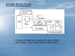
Advancements in Electrical
Discharge Machining
BY
VISHAL BORKAR
M. Tech(CAD/CAM)
I-Semester
 Most extensively used non-conventional, controlled metal
removal process that is used to remove metal by means of
electrical spark erosion.
 The first EDM system was developed by Lazarenko in 1943.
 The metal removal process is performed by applying a
pulsating (on/off) electrical charge of high frequency current
through the electrode to the work piece immersed in dielectric
medium.
INTRODUCTION
 A tool
 Work piece
 Servo mechanism
 Dielectric fluid
MAIN COMPONENTS OF EDM
EDM SYSTEM
It consist of a table with x,y axis and z axis is vertical.
A NC system, a tank in which there is dielectric fluid.
• Tool electrode is to provide electrical energy to the work material.
• Basic desirable characters of tool material:-
 High thermal conductivity
High electrical conductivity
High melting point to reduce its wear rate
Ease to manufacture
EDM TOOLS
TYPES OF ELECTRODES
 Metallic electrodes
 Non metallic electrodes
 Combined metallic and non metallic
 Metallic coating on insulators
Most commonly used: Brass, Copper, Graphite, Al alloys.
 It acts as an insulator until sufficiently high potential is reached .
 Acts as a coolant medium and reduces the extremely high temp. in the
arc gap.
 It is pumped through the arc gap to flush away the eroded particles
between the work-piece and the electrode which is critical to high metal
removal rates and good machining conditions.
Basic requirements are:
o Low viscosity
o Absence of toxic vapours
o Chemical neutrality
o Low cost.
Methods of fluid application
• Normal flow
• Reverse flow
• Jet flushing
DIELECTRIC FLUIDS
• Melting and vaporization
BASIC PRINCIPLE OF EDM
Electrical energy turned into thermal energy through a series of discrete
electrical discharges .
The thermal energy generates a channel of plasma between the cathode
and the anode.
workpiece +anode
-cathode
(a) Tool and work piece immersed in
dielectric liquid.
(b) A spark is generated between tool and
work piece.
(c) The high temperature causes the melting
and vaporization of electrodes.
(d) At the end of the pulse, the molten
material is ejected from surface, leaving a
shallow crater.
electrode
EXAMPLES OF EDM
Stepped cavities High speed turbine and mould for the
screw thread of PET bottles
Intricately detailed automobile part Turbine blades
 Conventional EDM Or Die Sinking
 Wire EDM
TYPES OF EDM
 One of the most widely used non-traditional processes.
 Sparks occur across a small gap between tool and work.
 Requires dielectric fluid, which creates a path for each discharge as
fluid becomes ionized in the gap.
Conventional EDM Or Die Sinking
ELECTRODE/ TOOL MATERIAL:
Graphite,copper, Brass
Dielectric Fluid:
Paraffin or transformer oil, mineral oils, kerosene, distilled and deionized water etc.
Work material:
Machining materials like: - steels, super alloys, refractory’s.
Applications
 Production parts
 Delicate parts
 Hole drilling
 Machining of hard metals.
 Tooling for many mechanical processes
 moulds for plastic injection moulding
 extrusion dies
 wire drawing dies
 forging and heading dies
 Work is fed slowly past wire along desired cutting path, like a band
saw operation.
 CNC used for motion control
 While cutting, wire is continuously advanced between supply
spool/reel and take up spool to maintain a constant diameter.
 Dielectric required, using nozzles directed at tool work interface or
submerging work part
 Wire is made up of brass, copper or tungsten. (0.25 mm in diameter)
WIRE EDM
 The wire is kept in tension using a mechanical tensioning
device reducing the tendency of producing inaccurate parts.
 The material is eroded ahead of the wire and there is no direct
contact between the work piece and the wire, eliminating the
mechanical stresses during machining.
Wire EDM Applications:
 Ideal for stamping die components.
 Other tools and parts with intricate outlines shapes, such as lathe
form tools, extrusion dies and flat templates
EDM DEVELOPMENT
Dry EDM EDG Hole Drilling EDM
ECDM:
 It is an emerging hybrid machining process used in precision
machining of hard and brittle non-conducting materials.
 Comprising the techniques of electrochemical machining
(ECM) and electro discharge machining (EDM).
 Also referred as electrochemical spark machining (ECSM)
process.
 Support a variety of materials including metals, ceramics,
composites, alumina, glass, etc.
inert
material
copper
Dilute HCl
 Application of voltage to the cell results in reduction of electrolyte with liberation
of hydrogen gas at the cathode tip.
 When voltage exceeds beyond a threshold value, hydrogen gas bubbles grow in
size.
Discharge occurs at the tip of the cathode and Machining takes place on the work
piece
 Suitable material (aluminium, chromium, copper, silicon carbide, etc.) in
powder form is mixed into the dielectric fluid used in EDM.
 When a voltage of 80 –320 V is applied between the tool electrode and the
work piece placed close to each other, an electric field is generated
 The additive particles fill up the spark gap. The high electric field energies
powder particles which act as conductors.
PMEDM (Powder Mixed Electrical Discharge Machining)
 These conductive particles form chains at different places under
sparking area, which bridges the gap between tool electrode and work
piece material.
 Due to bridging effect, the gap voltage and insulting strength of
dielectric fluid reduces which result in easy short circuiting.
 Due to this, electric density decreases and hence uniform distribution
of sparking takes place.
 This leads to uniform erosion on work piece which results in
improvement in surface finish.
 Dry EDM is a 'green' environment friendly EDM technique in which instead of
mineral oil based liquid dielectric, gas at high pressure is used as the dielectric
medium.
 A high velocity gas flow is supplied through a thin walled pipe electrode.
 The role of the gas is to remove the debris from the gap and to cool the inter
electrode gap.
 During the pulse interval, the gas jet blows off the plasma formed by previous
pulse discharge and decreases the temperatures of the discharge spots.
DRY EDM
INNOVATIVE EDM TECHNOLOGIES
Factors favouring dry EDM:
i .No fire hazard
ii. No toxic fumes generated
iii. No need for special treatment for disposal of sludge, dielectric waste, etc
Other Advantages:
a) Very low tool wear.
b) lower residual stresses
c) Higher Precision.
d) Smaller discharge gap length.
f) No electrolytic corrosion of w/p (as compared to water based dielectrics).
Major Disadvantages:
i. Low material removal rate (MRR)
ii. Poor process stability
 Removes conductive materials by rapid spark discharges between
a rotating tool and work piece that are separated by a flowing
dielectric fluid.
 The spark gap is normally held at 0.013 to 0.075 mm by the
servomechanism that controls the motion of the work piece
 The conductive wheel, usually made of graphite, rotates at 30 to
180 m/min in a dielectric bath of filtered hydrocarbon oil.
 The work piece is usually connected to the positive terminal of the
dc power supply.
EDG (Electro Discharge Grinding)
 The work piece is machined using a stream of electric sparks. Each
spark discharge melts or vaporizes a small amount of metal from the
work piece surface
 Material removal rates range from 0.16 to 2.54 cm3/min.
1. Steel and carbide
2. Thin sections (abrasive wheel where pressure might cause distortion)
3. Brittle materials or fragile parts on which abrasive materials might
cause fracturing.
APPLICATIONS
EDM HOLE DRILLING
 It was designed especially for fast, accurate small and deep-hole drilling
applications.
A precision tubular electrode (generally brass or copper) mounted into the
drill chuck located on the "Z" axis and held in location on top of the work piece
by the ceramic guide.
 The top of the work piece is located and the drilling depth is set.
 The electrode rotation is turned on and the de-ionized water solution,
which is pressurized between 50 -100 kg/cm2, is sent through the
tubular electrode as a flushing agent.
 The power supply parameters are set-which normally consist of on-
time, off-time, peak current and amount of capacitance.
 At this point, the discharge is turned on to begin the drilling cycle.
At the end of the drilling cycle, the discharge is turned off and the
"Z" axis is retracted above the work piece.
Applications:-
 Mould and part manufacturing-injection nozzles
 Oil drain holes, hydraulic cylinders and dowel pins,
 turbine blades, ball bearings and safety wire holes in hex nuts.
 www.wikipedia.com
 (http://www.atlantaedm.com/articles/a8-history-of-edm.php)
 (http://www.jobshop.com/techinfo/papers/whatiswireedm.shtml)
 (http://www.britannica.com/EBchecked/topic/354662/machine-
tool/39176/Nonconventional-methods-ofmachining)
 Research performed on the EDM process (http://www.fs.uni-
lj.si/lat/edm/index.html)
REFERENCES:
Edm

Edm

  • 1.
    Advancements in Electrical DischargeMachining BY VISHAL BORKAR M. Tech(CAD/CAM) I-Semester
  • 2.
     Most extensivelyused non-conventional, controlled metal removal process that is used to remove metal by means of electrical spark erosion.  The first EDM system was developed by Lazarenko in 1943.  The metal removal process is performed by applying a pulsating (on/off) electrical charge of high frequency current through the electrode to the work piece immersed in dielectric medium. INTRODUCTION
  • 3.
     A tool Work piece  Servo mechanism  Dielectric fluid MAIN COMPONENTS OF EDM
  • 4.
    EDM SYSTEM It consistof a table with x,y axis and z axis is vertical. A NC system, a tank in which there is dielectric fluid.
  • 5.
    • Tool electrodeis to provide electrical energy to the work material. • Basic desirable characters of tool material:-  High thermal conductivity High electrical conductivity High melting point to reduce its wear rate Ease to manufacture EDM TOOLS TYPES OF ELECTRODES  Metallic electrodes  Non metallic electrodes  Combined metallic and non metallic  Metallic coating on insulators Most commonly used: Brass, Copper, Graphite, Al alloys.
  • 6.
     It actsas an insulator until sufficiently high potential is reached .  Acts as a coolant medium and reduces the extremely high temp. in the arc gap.  It is pumped through the arc gap to flush away the eroded particles between the work-piece and the electrode which is critical to high metal removal rates and good machining conditions. Basic requirements are: o Low viscosity o Absence of toxic vapours o Chemical neutrality o Low cost. Methods of fluid application • Normal flow • Reverse flow • Jet flushing DIELECTRIC FLUIDS
  • 7.
    • Melting andvaporization BASIC PRINCIPLE OF EDM Electrical energy turned into thermal energy through a series of discrete electrical discharges . The thermal energy generates a channel of plasma between the cathode and the anode.
  • 8.
    workpiece +anode -cathode (a) Tooland work piece immersed in dielectric liquid. (b) A spark is generated between tool and work piece. (c) The high temperature causes the melting and vaporization of electrodes. (d) At the end of the pulse, the molten material is ejected from surface, leaving a shallow crater. electrode
  • 9.
    EXAMPLES OF EDM Steppedcavities High speed turbine and mould for the screw thread of PET bottles Intricately detailed automobile part Turbine blades
  • 10.
     Conventional EDMOr Die Sinking  Wire EDM TYPES OF EDM
  • 11.
     One ofthe most widely used non-traditional processes.  Sparks occur across a small gap between tool and work.  Requires dielectric fluid, which creates a path for each discharge as fluid becomes ionized in the gap. Conventional EDM Or Die Sinking
  • 12.
    ELECTRODE/ TOOL MATERIAL: Graphite,copper,Brass Dielectric Fluid: Paraffin or transformer oil, mineral oils, kerosene, distilled and deionized water etc. Work material: Machining materials like: - steels, super alloys, refractory’s. Applications  Production parts  Delicate parts  Hole drilling  Machining of hard metals.  Tooling for many mechanical processes  moulds for plastic injection moulding  extrusion dies  wire drawing dies  forging and heading dies
  • 13.
     Work isfed slowly past wire along desired cutting path, like a band saw operation.  CNC used for motion control  While cutting, wire is continuously advanced between supply spool/reel and take up spool to maintain a constant diameter.  Dielectric required, using nozzles directed at tool work interface or submerging work part  Wire is made up of brass, copper or tungsten. (0.25 mm in diameter) WIRE EDM
  • 14.
     The wireis kept in tension using a mechanical tensioning device reducing the tendency of producing inaccurate parts.  The material is eroded ahead of the wire and there is no direct contact between the work piece and the wire, eliminating the mechanical stresses during machining. Wire EDM Applications:  Ideal for stamping die components.  Other tools and parts with intricate outlines shapes, such as lathe form tools, extrusion dies and flat templates
  • 15.
    EDM DEVELOPMENT Dry EDMEDG Hole Drilling EDM
  • 16.
    ECDM:  It isan emerging hybrid machining process used in precision machining of hard and brittle non-conducting materials.  Comprising the techniques of electrochemical machining (ECM) and electro discharge machining (EDM).  Also referred as electrochemical spark machining (ECSM) process.  Support a variety of materials including metals, ceramics, composites, alumina, glass, etc.
  • 17.
    inert material copper Dilute HCl  Applicationof voltage to the cell results in reduction of electrolyte with liberation of hydrogen gas at the cathode tip.  When voltage exceeds beyond a threshold value, hydrogen gas bubbles grow in size. Discharge occurs at the tip of the cathode and Machining takes place on the work piece
  • 18.
     Suitable material(aluminium, chromium, copper, silicon carbide, etc.) in powder form is mixed into the dielectric fluid used in EDM.  When a voltage of 80 –320 V is applied between the tool electrode and the work piece placed close to each other, an electric field is generated  The additive particles fill up the spark gap. The high electric field energies powder particles which act as conductors. PMEDM (Powder Mixed Electrical Discharge Machining)
  • 19.
     These conductiveparticles form chains at different places under sparking area, which bridges the gap between tool electrode and work piece material.  Due to bridging effect, the gap voltage and insulting strength of dielectric fluid reduces which result in easy short circuiting.  Due to this, electric density decreases and hence uniform distribution of sparking takes place.  This leads to uniform erosion on work piece which results in improvement in surface finish.
  • 20.
     Dry EDMis a 'green' environment friendly EDM technique in which instead of mineral oil based liquid dielectric, gas at high pressure is used as the dielectric medium.  A high velocity gas flow is supplied through a thin walled pipe electrode.  The role of the gas is to remove the debris from the gap and to cool the inter electrode gap.  During the pulse interval, the gas jet blows off the plasma formed by previous pulse discharge and decreases the temperatures of the discharge spots. DRY EDM INNOVATIVE EDM TECHNOLOGIES
  • 21.
    Factors favouring dryEDM: i .No fire hazard ii. No toxic fumes generated iii. No need for special treatment for disposal of sludge, dielectric waste, etc Other Advantages: a) Very low tool wear. b) lower residual stresses c) Higher Precision. d) Smaller discharge gap length. f) No electrolytic corrosion of w/p (as compared to water based dielectrics). Major Disadvantages: i. Low material removal rate (MRR) ii. Poor process stability
  • 22.
     Removes conductivematerials by rapid spark discharges between a rotating tool and work piece that are separated by a flowing dielectric fluid.  The spark gap is normally held at 0.013 to 0.075 mm by the servomechanism that controls the motion of the work piece  The conductive wheel, usually made of graphite, rotates at 30 to 180 m/min in a dielectric bath of filtered hydrocarbon oil.  The work piece is usually connected to the positive terminal of the dc power supply. EDG (Electro Discharge Grinding)
  • 23.
     The workpiece is machined using a stream of electric sparks. Each spark discharge melts or vaporizes a small amount of metal from the work piece surface  Material removal rates range from 0.16 to 2.54 cm3/min. 1. Steel and carbide 2. Thin sections (abrasive wheel where pressure might cause distortion) 3. Brittle materials or fragile parts on which abrasive materials might cause fracturing. APPLICATIONS
  • 24.
    EDM HOLE DRILLING It was designed especially for fast, accurate small and deep-hole drilling applications. A precision tubular electrode (generally brass or copper) mounted into the drill chuck located on the "Z" axis and held in location on top of the work piece by the ceramic guide.
  • 25.
     The topof the work piece is located and the drilling depth is set.  The electrode rotation is turned on and the de-ionized water solution, which is pressurized between 50 -100 kg/cm2, is sent through the tubular electrode as a flushing agent.  The power supply parameters are set-which normally consist of on- time, off-time, peak current and amount of capacitance.  At this point, the discharge is turned on to begin the drilling cycle. At the end of the drilling cycle, the discharge is turned off and the "Z" axis is retracted above the work piece.
  • 26.
    Applications:-  Mould andpart manufacturing-injection nozzles  Oil drain holes, hydraulic cylinders and dowel pins,  turbine blades, ball bearings and safety wire holes in hex nuts.
  • 27.
     www.wikipedia.com  (http://www.atlantaedm.com/articles/a8-history-of-edm.php) (http://www.jobshop.com/techinfo/papers/whatiswireedm.shtml)  (http://www.britannica.com/EBchecked/topic/354662/machine- tool/39176/Nonconventional-methods-ofmachining)  Research performed on the EDM process (http://www.fs.uni- lj.si/lat/edm/index.html) REFERENCES: