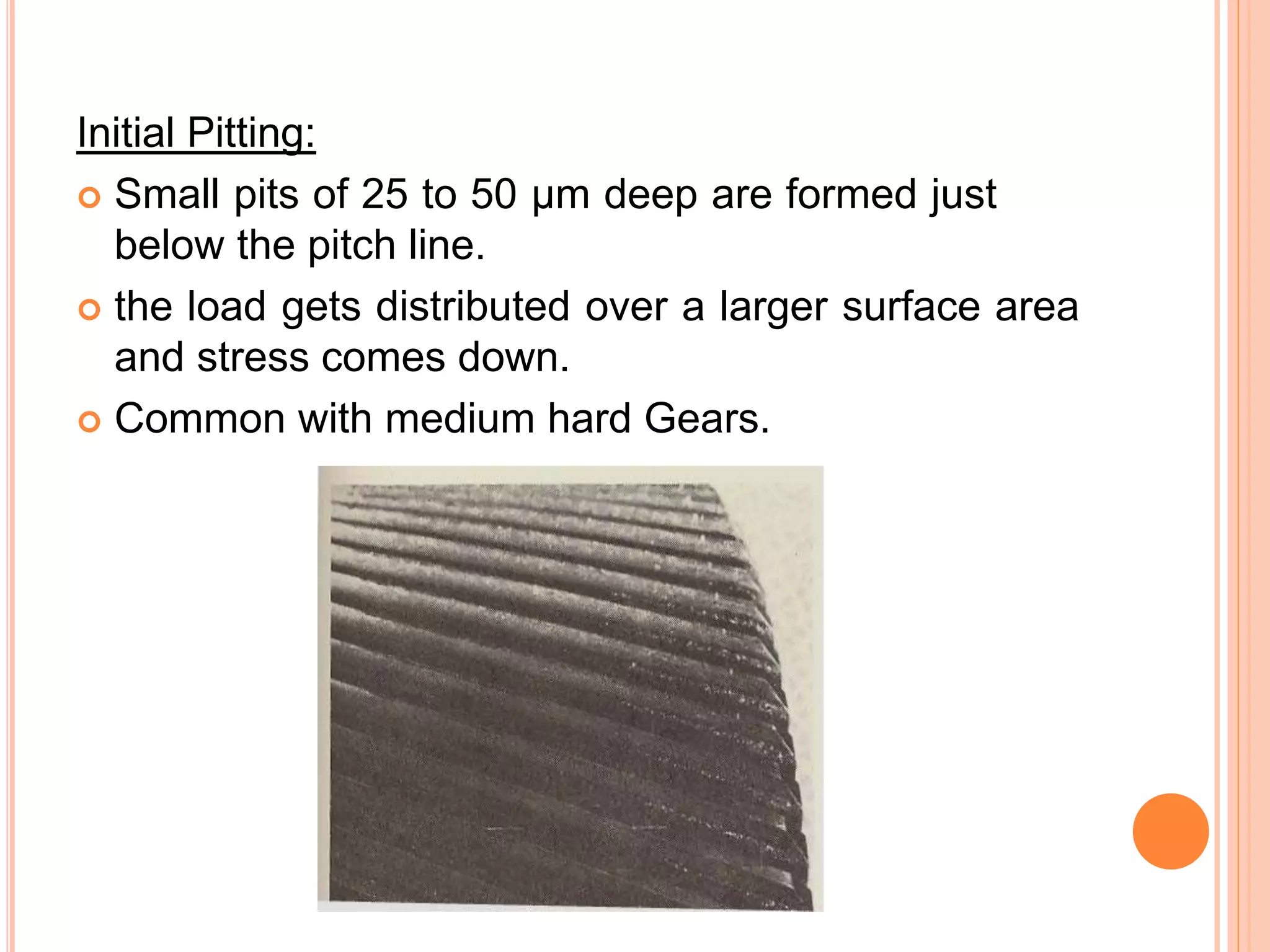
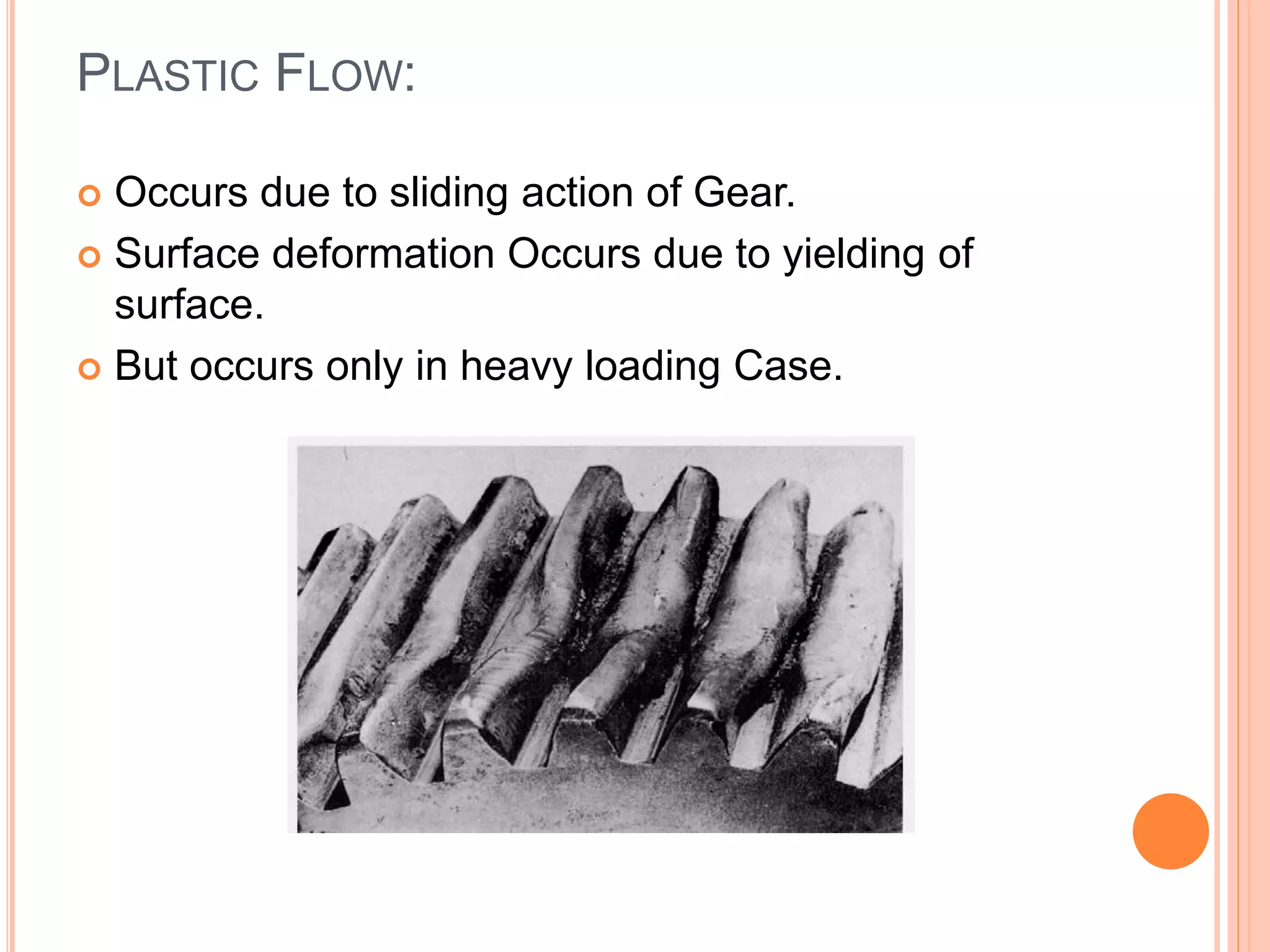
KUMARAGURU COLLEGE OF TECHNOLOGY
P15CCT104 - INTEGRATED MECHANICAL DESIGN
GEARS
Presented By,
RAGHUL S(17MCC006)
TABLE OF CONTENTS
 Introduction
 General Nomenclature
 Types Of Gears
 Gear Materials
 Gear Tooth Failure
INTRODUCTION:
 A gear is a wheel with teeth that mesh together with
other gears.
 Transmit motion by engaging teeth
 Two or more meshing gears, working in a
sequence, are called a gear train
 Used to change,
 Speed
 Torque
 Direction
GENERAL NOMENCLATURE
Face Width:
 The Face width of a gear is the length of teeth in an
axial plane.
Pressure Angle ( α ):
 Pressure angle is the leaning angle of a gear tooth, an
element determining the tooth profile.
Whole depth:
 The distance from the top of the tooth to the root; it is
equal to addendum plus dedendum or to working depth
plus clearance.
Working depth:
 Depth of engagement of two gears, that is, the sum of
their operating addendums.
Pitch circle:
 A Pitch circle is the curve of intersection of a pitch
surface of revolution and a plane of rotation.
Outside diameter:
 Diameter of the gear, measured from the tops of the
teeth.
Root diameter :
 Diameter of the gear, measured at the base of the tooth.
Clearance:
 Distance between the root circle of a gear and the
addendum circle of its mate.
Addendum:
 Radial distance between the pitch diameter and the
outside diameter.
Addendum circle:
 Coincides with the tops of the teeth of a gear and is
concentric with the standard pitch circle.
Dedendum:
 Radial distance from the depth of the tooth trough to the
pitch surface.
Dedendum Circle:
 The circle touching the bottom of the spaces between
the teeth of a gear wheel.
TYPES OF GEAR:
 Spur Gear
 Helical Gear
 Bevel Gear
 Worm Gear
 Rack And Pinion
 Herringbone Gear
SPUR GEAR:
 Most commonly used Gear type.
 Teeth are parallel to the axis of the gear.
 Transmit power from one shaft to other parallel
shaft.
Advantage:
Low Cost
Ease of manufacture
Availability
Disadvantage:
Only works with mating gear
Axis of each gear must be parallel
Applications:
Washing Machines, Rolling Mills, Marine
Engines.
HELICAL GEAR
 Teeth are at an angle to the gear axis
 This gradual arrangement makes helical gear
operate much more smoothly and quietly than spur
gear
 Can transmit power between Right angle or Parallel
Axis
Advantage:
Smooth and quiet due to gradual tooth
engagements
Parallel to perpendicular shaft arrangement
Disadvantage:
Difficult to Manufacture
Cost is High
Resulting axial thrust component
Applications:
Fertilizer industries, Printing industries, earth
moving industries, Conveyors, Elevators
BEVEL GEAR:
 Usefull when the direction of shaft location has to
be changed.
 Mounted on shaft that are 90deg apart, can also be
designed to work in other angles.
 Teeth can be straight, Spiral or Hypoid
Advantage:
Operate on Shafts intersecting at an Angle.
Sliding friction will be low.
Disadvantage:
Assembled with respective shaft precisely.
At high speed it will produce noise.
Applications:
Textile Machine, Sewing Machine.
WORM GEAR:
 Used when large Gear Reduction is needed.
 Have good intersecting property.
 Used widely in material Handling and transportation
machinery, machine tools etc…
Advantage:
Higher speed reduction could be secured;
speed reduction could be secured up to 300:1
Worm and worm gears operate silently
Disadvantage:
Manufacturing cost is high as compared with
manufacturing cost of bevel gear
Worm and worm gear set will have heavy
power losses.
Efficiency will be low
Applications:
 Tuning Instruments, Lifts/Elevators.
RACK AND PINION:
 Convert Rotational to Linear motion
 Round Gear – Pinion
Flat or Straight Gear – Rack
 Best example is Car Steering System.
Advantage:
Rack and pinion gives easier and more
compact control over the vehicle
Cheap, Compact, Robust.
Disadvantage:
The rack and pinion can only work with certain
levels of friction.
Applications:
Rack Elevators, Steering.
HERRINGBONE GEAR:
 Two helical gears that have been placed side by
side.
 Referred to as “double helical”.
 No thrust loading on the bearings
Advantage:
The double helical form balances the inherent
thrust forces.
Efficient transfer of torque and smooth motion
at very high rotational velocities.
Disadvantage:
High cost due to special gear shaping
equipment and special cutting tools.
Applications:
Used in Heavy Machinery.
GEAR MATERIALS:
 Numerous nonferrous alloys, cast irons, powder-
metallurgy and plastics are used in the manufacture
of gears.
 Steels - commonly used - high strength-to-weight
ratio and low cost.
 Plastics - cost or weight is a concern - Reduce
repair cost.
GEAR TOOTH FAILURE:
 Gear failure can occur in various modes.
 Care has to be taken to avoid such failures
 Types of Gear Tooth Failure:
 Scoring Failure
 Wear Failure
 Pitting Failure
 Plastic Flow
 Tooth Fracture
SCORING FAILURE:
 Occurs Due to Lubrication failure in Contact region
and metal to metal contact.
 Welding and tearing action resulting from metallic
contact removes the metal.
 Types of Scoring:
 Initial Scoring
 Moderate Scoring
 Destructive Scoring
Initial Scoring:
 Occurs by High spots left by previous machine.
 Lubrication failure at this point leads to Scoring
 Scoring stops when temperature, load and speed
remains unchanged.
Moderate Scoring:
 Occurs After initial scoring if the load, speed or oil
temperature increases, the scoring will spread over
to a larger area.
 Progresses at tolerable rate.
Destructive Scoring:
 If the load, speed or oil temperature
increases appreciably, then severe scoring sets in
with heavy metal will occur.
 Predominant over Pitch line since the lubrication
is least at that region.
WEAR FAILURE:
 Wear is a kind of tooth damage where a layers of
metal are removed more or less uniformly from the
surface.
 Tooth Thins and get weakened.
 Cause of gear tooth wear is
 Adhesive Wear
 Abrasive Wear
 Corrosion Wear
Adhesive Wear:
 Hard to detect.
 Occurs from start since the rate of wear is low.
 When the load and speed of operation are more
than mild wear conditions, moderate wear takes
place with higher rate.
 Occurs over long Period.
Abrasive Wear:
 Reason for the failure of open gearing and closed
gearing of machine operated in Abrasive materials.
 Depending on the size, shape and concentration of
the abrasives the wear will change.
Corrosion Wear:
 Due to the chemical action of the lubricating oil or
the additives.
PITTING FAILURE:
 Surface fatigue failure of the gear tooth.
 Occur due to repeated loading of tooth surface and
contact stress.
 Pit is formed.
 Impact load resulting from pitting may cause failure.
 Types of Pitting
 Initial Pitting
 Progressive Pitting
Initial Pitting:
 Small pits of 25 to 50 μm deep are formed just
below the pitch line.
 the load gets distributed over a larger surface area
and stress comes down.
 Common with medium hard Gears.
Progressive Pitting:
 High load and corrective action of initial pitting
leads to Progressive Pitting.
 Pitting begins on the tooth flanks near the line
along the tooth passing through the pitch point.
 Very rare in tooth Face.
PLASTIC FLOW:
 Occurs due to sliding action of Gear.
 Surface deformation Occurs due to yielding of
surface.
 But occurs only in heavy loading Case.
TOOTH FRACTURE:
 Dangerous kind of gear failure leads to disablement
of drive and frequently to damage of other
components.
 Occurs over a long a period of time.
 Tooth failure may result low-cycle fatigue, Repeated
cyclic load
THANK YOU

Gears And its types

  • 1.
    KUMARAGURU COLLEGE OFTECHNOLOGY P15CCT104 - INTEGRATED MECHANICAL DESIGN GEARS Presented By, RAGHUL S(17MCC006)
  • 2.
    TABLE OF CONTENTS Introduction  General Nomenclature  Types Of Gears  Gear Materials  Gear Tooth Failure
  • 3.
    INTRODUCTION:  A gearis a wheel with teeth that mesh together with other gears.  Transmit motion by engaging teeth  Two or more meshing gears, working in a sequence, are called a gear train  Used to change,  Speed  Torque  Direction
  • 4.
  • 5.
    Face Width:  TheFace width of a gear is the length of teeth in an axial plane. Pressure Angle ( α ):  Pressure angle is the leaning angle of a gear tooth, an element determining the tooth profile. Whole depth:  The distance from the top of the tooth to the root; it is equal to addendum plus dedendum or to working depth plus clearance. Working depth:  Depth of engagement of two gears, that is, the sum of their operating addendums.
  • 6.
    Pitch circle:  APitch circle is the curve of intersection of a pitch surface of revolution and a plane of rotation. Outside diameter:  Diameter of the gear, measured from the tops of the teeth. Root diameter :  Diameter of the gear, measured at the base of the tooth. Clearance:  Distance between the root circle of a gear and the addendum circle of its mate.
  • 7.
    Addendum:  Radial distancebetween the pitch diameter and the outside diameter. Addendum circle:  Coincides with the tops of the teeth of a gear and is concentric with the standard pitch circle. Dedendum:  Radial distance from the depth of the tooth trough to the pitch surface. Dedendum Circle:  The circle touching the bottom of the spaces between the teeth of a gear wheel.
  • 9.
    TYPES OF GEAR: Spur Gear  Helical Gear  Bevel Gear  Worm Gear  Rack And Pinion  Herringbone Gear
  • 10.
    SPUR GEAR:  Mostcommonly used Gear type.  Teeth are parallel to the axis of the gear.  Transmit power from one shaft to other parallel shaft.
  • 11.
    Advantage: Low Cost Ease ofmanufacture Availability Disadvantage: Only works with mating gear Axis of each gear must be parallel Applications: Washing Machines, Rolling Mills, Marine Engines.
  • 12.
    HELICAL GEAR  Teethare at an angle to the gear axis  This gradual arrangement makes helical gear operate much more smoothly and quietly than spur gear  Can transmit power between Right angle or Parallel Axis
  • 13.
    Advantage: Smooth and quietdue to gradual tooth engagements Parallel to perpendicular shaft arrangement Disadvantage: Difficult to Manufacture Cost is High Resulting axial thrust component Applications: Fertilizer industries, Printing industries, earth moving industries, Conveyors, Elevators
  • 14.
    BEVEL GEAR:  Usefullwhen the direction of shaft location has to be changed.  Mounted on shaft that are 90deg apart, can also be designed to work in other angles.  Teeth can be straight, Spiral or Hypoid
  • 15.
    Advantage: Operate on Shaftsintersecting at an Angle. Sliding friction will be low. Disadvantage: Assembled with respective shaft precisely. At high speed it will produce noise. Applications: Textile Machine, Sewing Machine.
  • 16.
    WORM GEAR:  Usedwhen large Gear Reduction is needed.  Have good intersecting property.  Used widely in material Handling and transportation machinery, machine tools etc…
  • 17.
    Advantage: Higher speed reductioncould be secured; speed reduction could be secured up to 300:1 Worm and worm gears operate silently Disadvantage: Manufacturing cost is high as compared with manufacturing cost of bevel gear Worm and worm gear set will have heavy power losses. Efficiency will be low Applications:  Tuning Instruments, Lifts/Elevators.
  • 18.
    RACK AND PINION: Convert Rotational to Linear motion  Round Gear – Pinion Flat or Straight Gear – Rack  Best example is Car Steering System.
  • 19.
    Advantage: Rack and piniongives easier and more compact control over the vehicle Cheap, Compact, Robust. Disadvantage: The rack and pinion can only work with certain levels of friction. Applications: Rack Elevators, Steering.
  • 20.
    HERRINGBONE GEAR:  Twohelical gears that have been placed side by side.  Referred to as “double helical”.  No thrust loading on the bearings
  • 21.
    Advantage: The double helicalform balances the inherent thrust forces. Efficient transfer of torque and smooth motion at very high rotational velocities. Disadvantage: High cost due to special gear shaping equipment and special cutting tools. Applications: Used in Heavy Machinery.
  • 22.
    GEAR MATERIALS:  Numerousnonferrous alloys, cast irons, powder- metallurgy and plastics are used in the manufacture of gears.  Steels - commonly used - high strength-to-weight ratio and low cost.  Plastics - cost or weight is a concern - Reduce repair cost.
  • 23.
    GEAR TOOTH FAILURE: Gear failure can occur in various modes.  Care has to be taken to avoid such failures  Types of Gear Tooth Failure:  Scoring Failure  Wear Failure  Pitting Failure  Plastic Flow  Tooth Fracture
  • 24.
    SCORING FAILURE:  OccursDue to Lubrication failure in Contact region and metal to metal contact.  Welding and tearing action resulting from metallic contact removes the metal.  Types of Scoring:  Initial Scoring  Moderate Scoring  Destructive Scoring
  • 25.
    Initial Scoring:  Occursby High spots left by previous machine.  Lubrication failure at this point leads to Scoring  Scoring stops when temperature, load and speed remains unchanged.
  • 26.
    Moderate Scoring:  OccursAfter initial scoring if the load, speed or oil temperature increases, the scoring will spread over to a larger area.  Progresses at tolerable rate.
  • 27.
    Destructive Scoring:  Ifthe load, speed or oil temperature increases appreciably, then severe scoring sets in with heavy metal will occur.  Predominant over Pitch line since the lubrication is least at that region.
  • 28.
    WEAR FAILURE:  Wearis a kind of tooth damage where a layers of metal are removed more or less uniformly from the surface.  Tooth Thins and get weakened.  Cause of gear tooth wear is  Adhesive Wear  Abrasive Wear  Corrosion Wear
  • 29.
    Adhesive Wear:  Hardto detect.  Occurs from start since the rate of wear is low.  When the load and speed of operation are more than mild wear conditions, moderate wear takes place with higher rate.  Occurs over long Period.
  • 30.
    Abrasive Wear:  Reasonfor the failure of open gearing and closed gearing of machine operated in Abrasive materials.  Depending on the size, shape and concentration of the abrasives the wear will change.
  • 31.
    Corrosion Wear:  Dueto the chemical action of the lubricating oil or the additives.
  • 32.
    PITTING FAILURE:  Surfacefatigue failure of the gear tooth.  Occur due to repeated loading of tooth surface and contact stress.  Pit is formed.  Impact load resulting from pitting may cause failure.  Types of Pitting  Initial Pitting  Progressive Pitting
  • 33.
    Initial Pitting:  Smallpits of 25 to 50 μm deep are formed just below the pitch line.  the load gets distributed over a larger surface area and stress comes down.  Common with medium hard Gears.
  • 34.
    Progressive Pitting:  Highload and corrective action of initial pitting leads to Progressive Pitting.  Pitting begins on the tooth flanks near the line along the tooth passing through the pitch point.  Very rare in tooth Face.
  • 35.
    PLASTIC FLOW:  Occursdue to sliding action of Gear.  Surface deformation Occurs due to yielding of surface.  But occurs only in heavy loading Case.
  • 36.
    TOOTH FRACTURE:  Dangerouskind of gear failure leads to disablement of drive and frequently to damage of other components.  Occurs over a long a period of time.  Tooth failure may result low-cycle fatigue, Repeated cyclic load
  • 37.