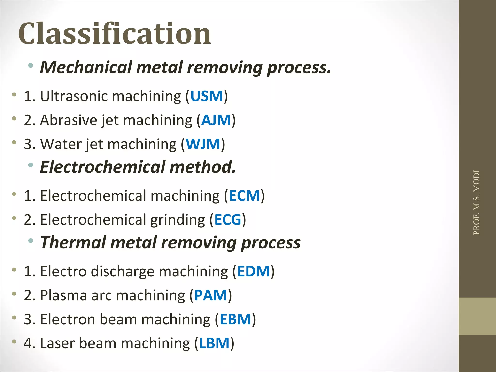
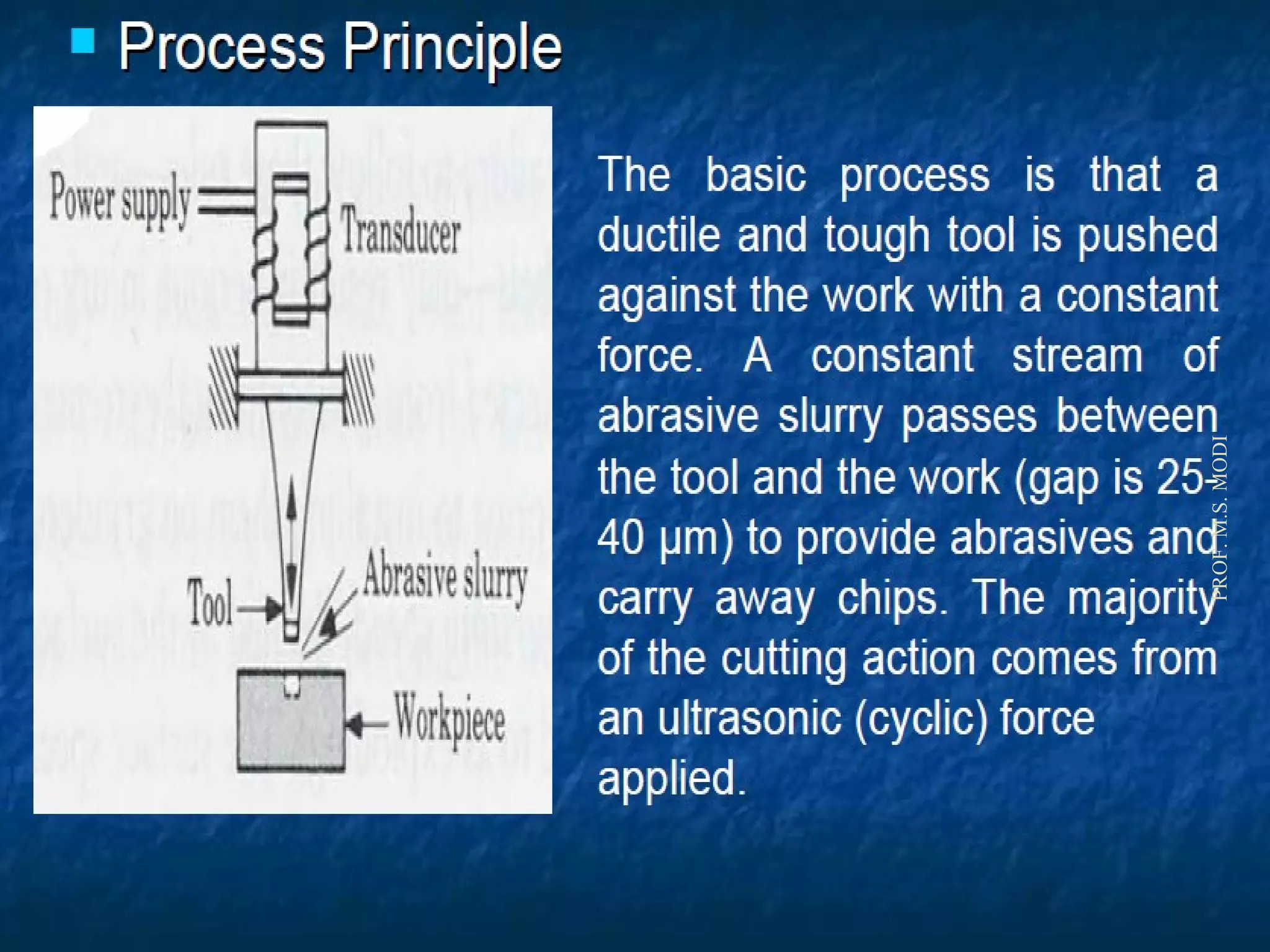
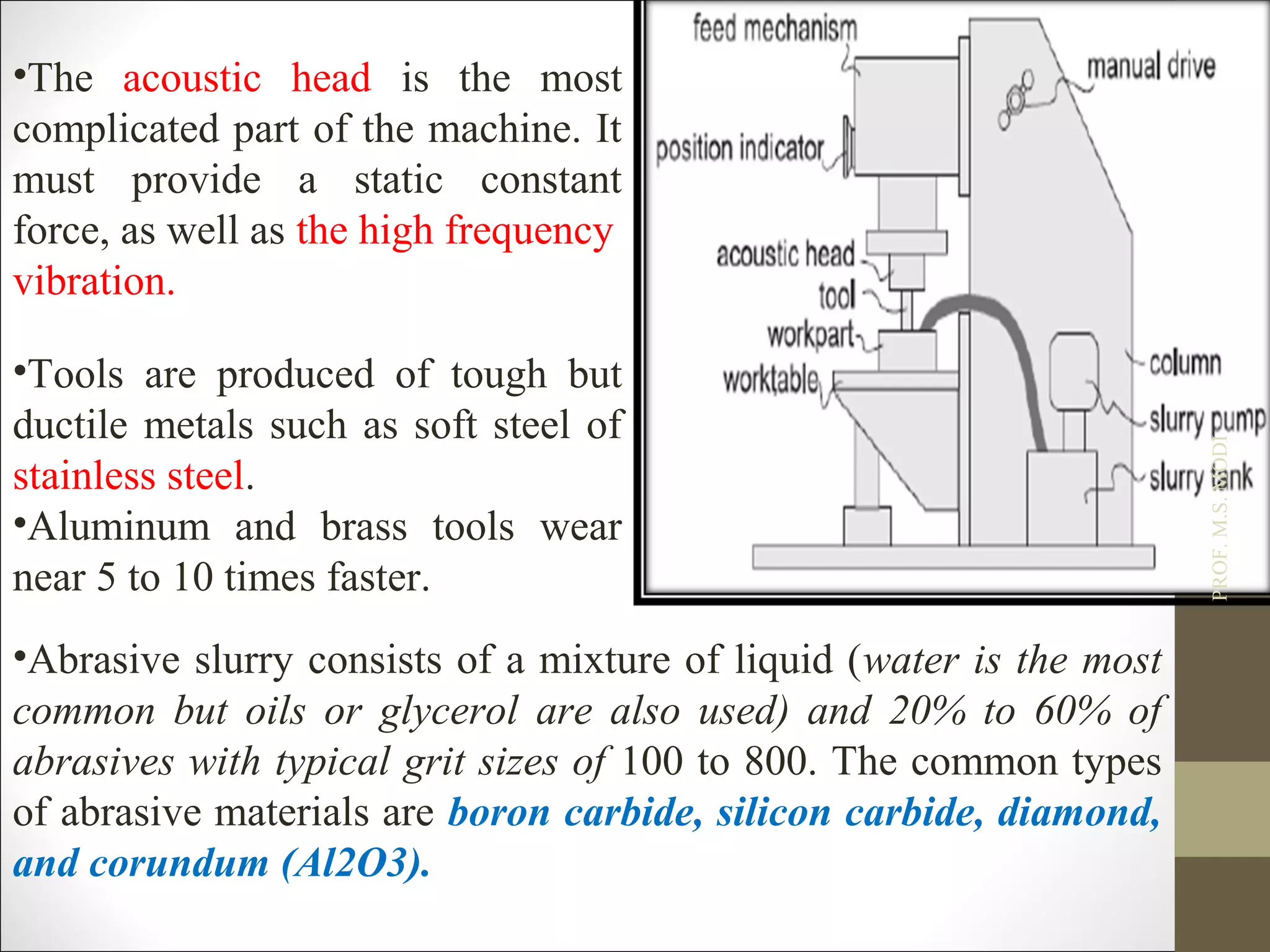
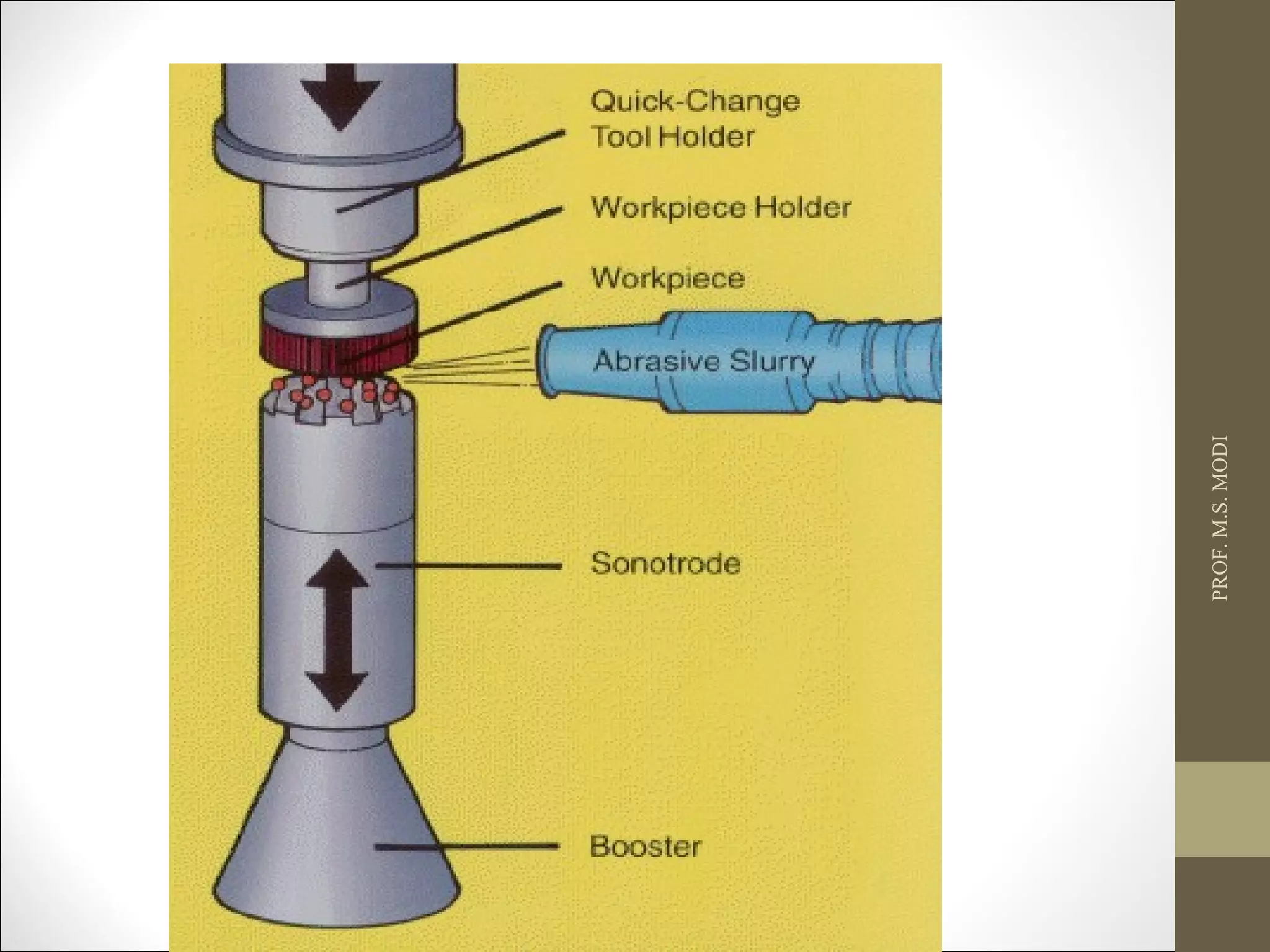
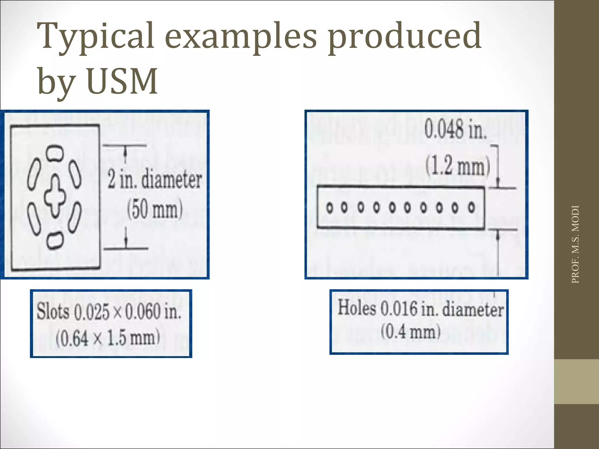
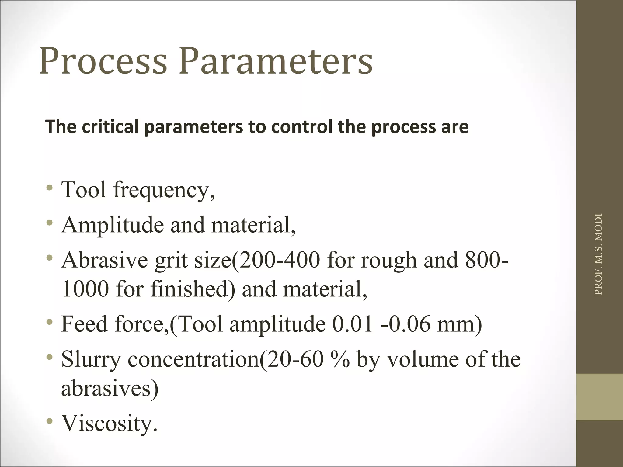
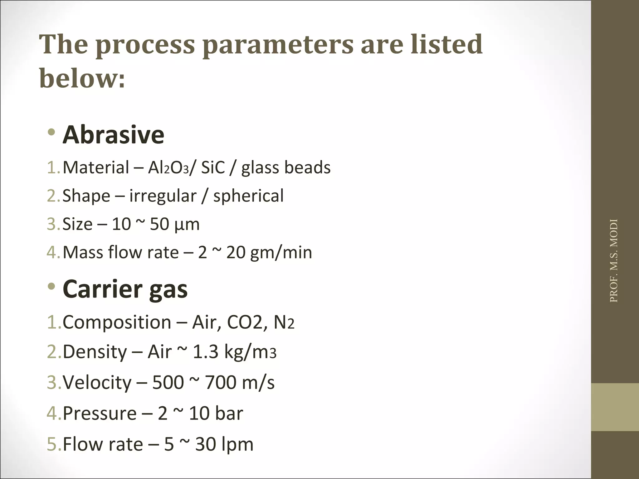
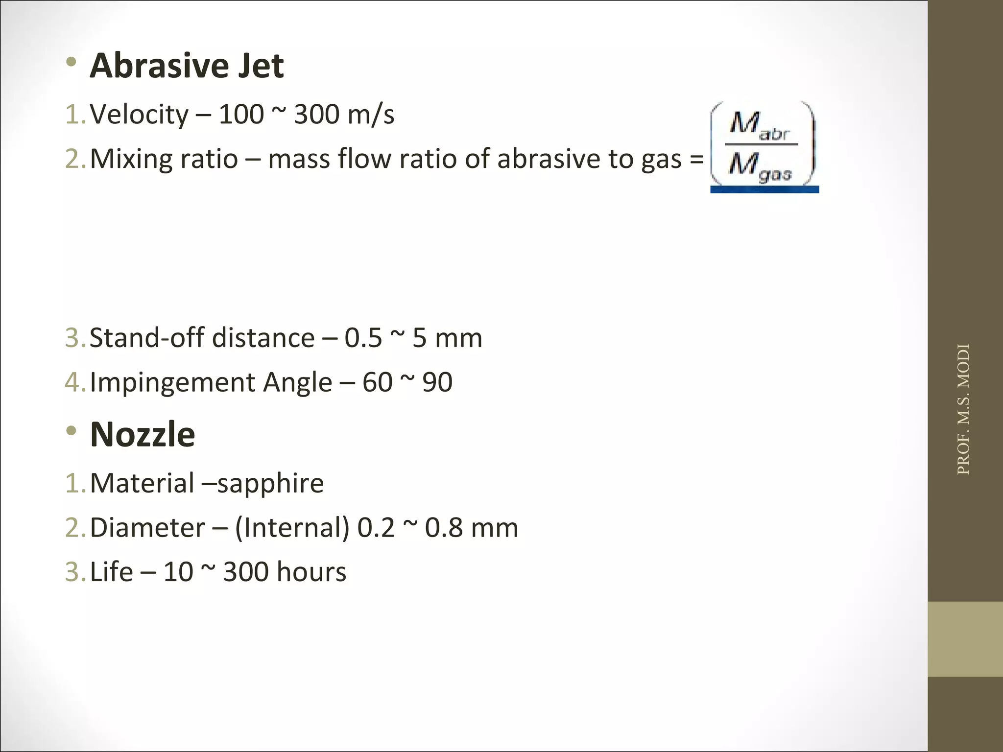
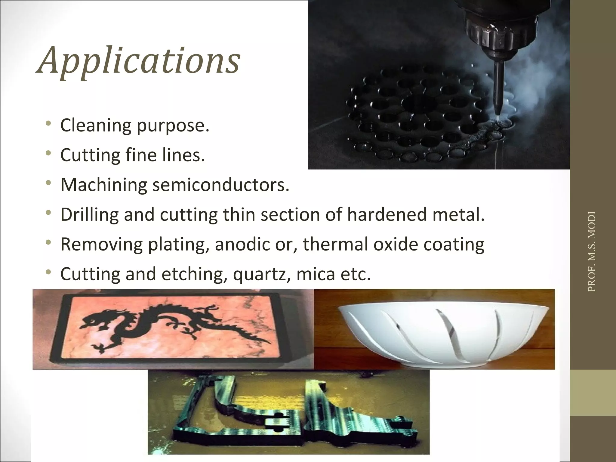
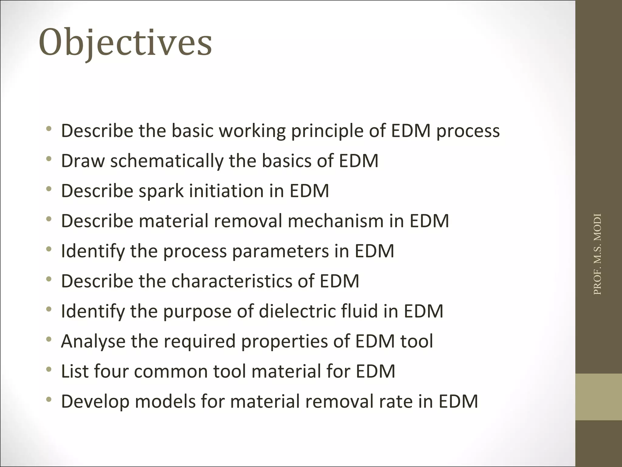
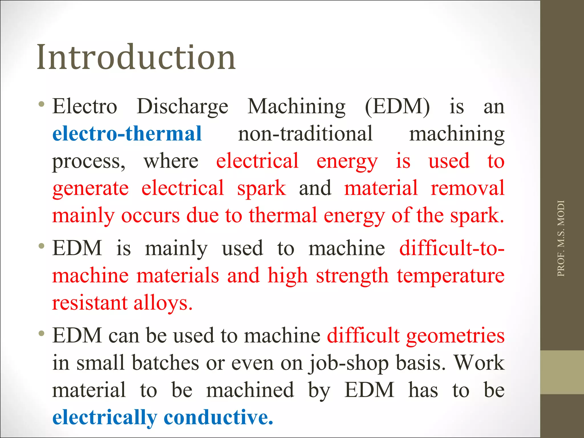
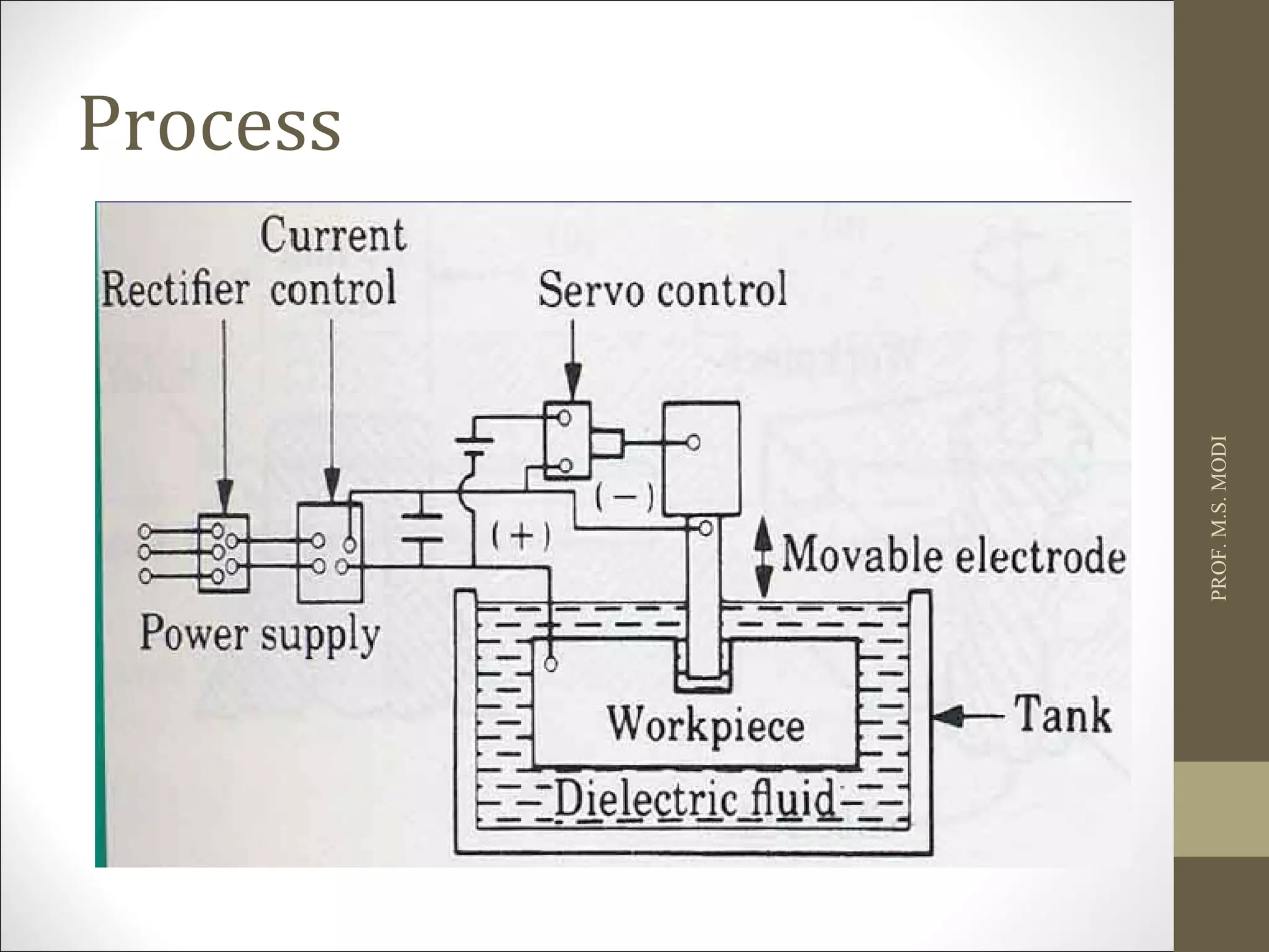
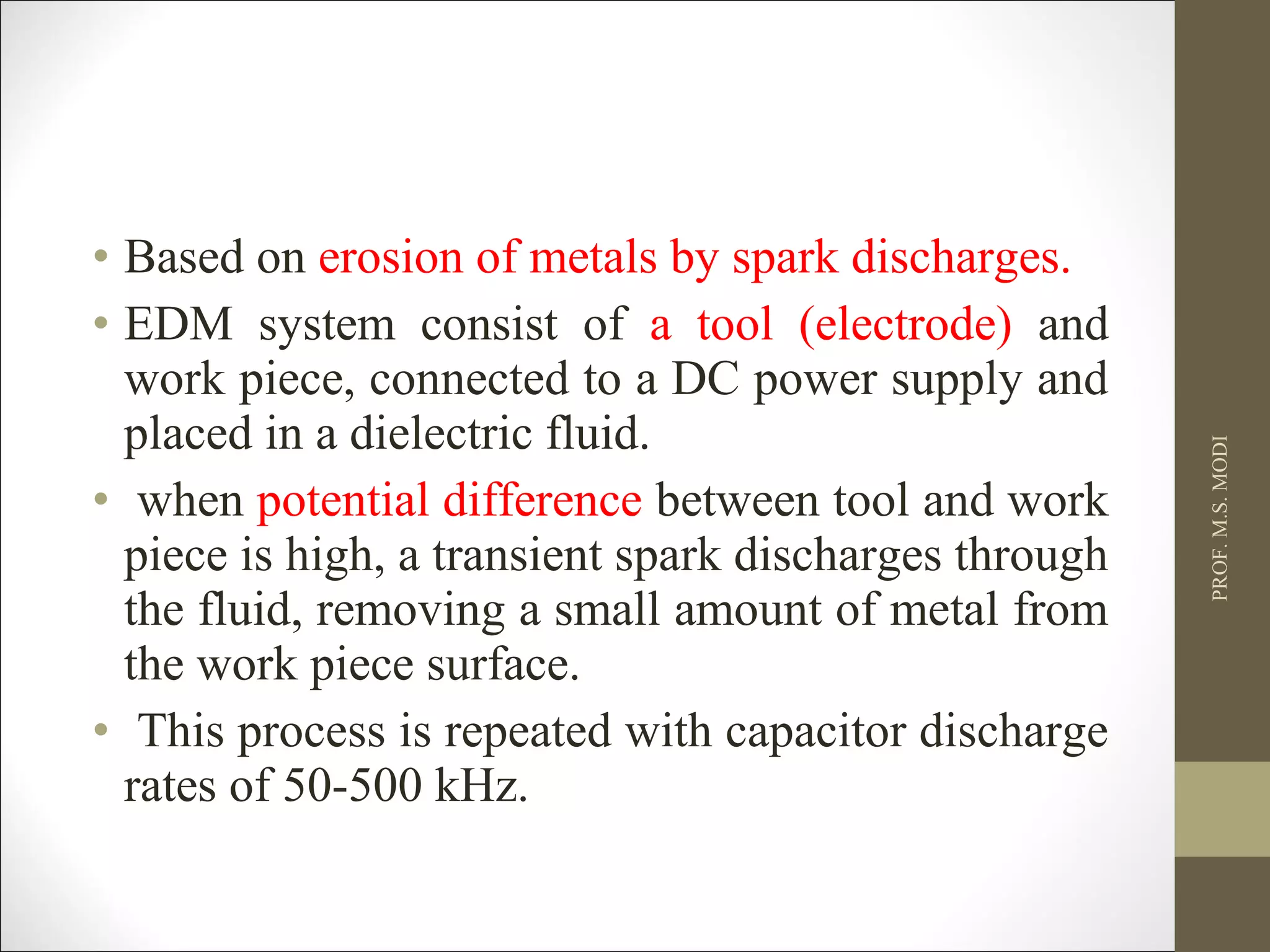
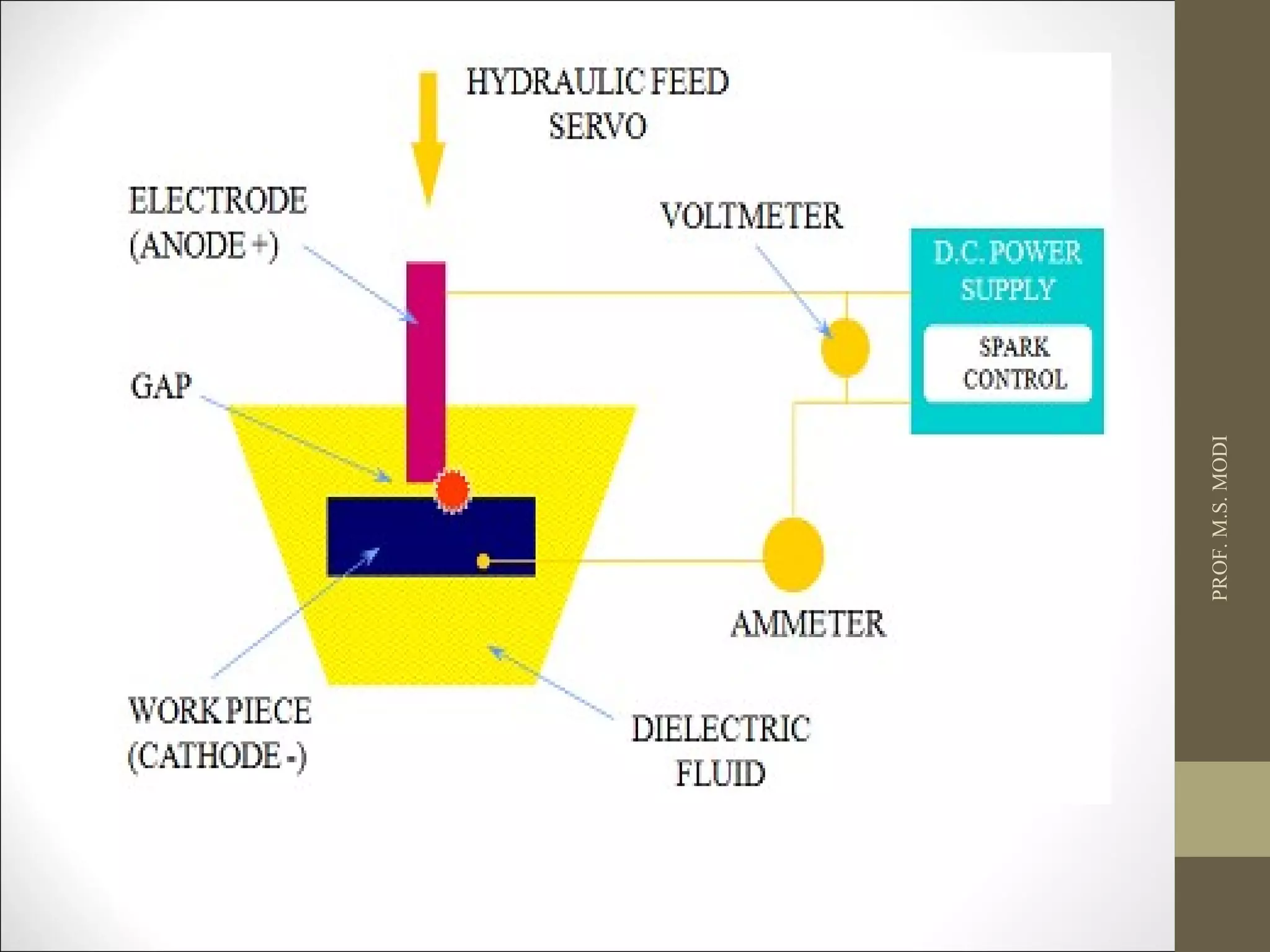
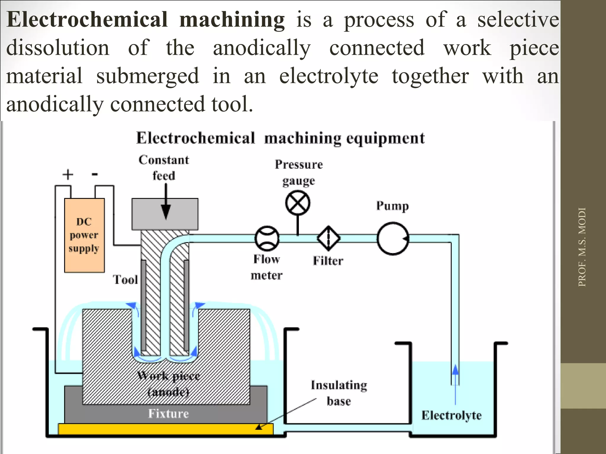
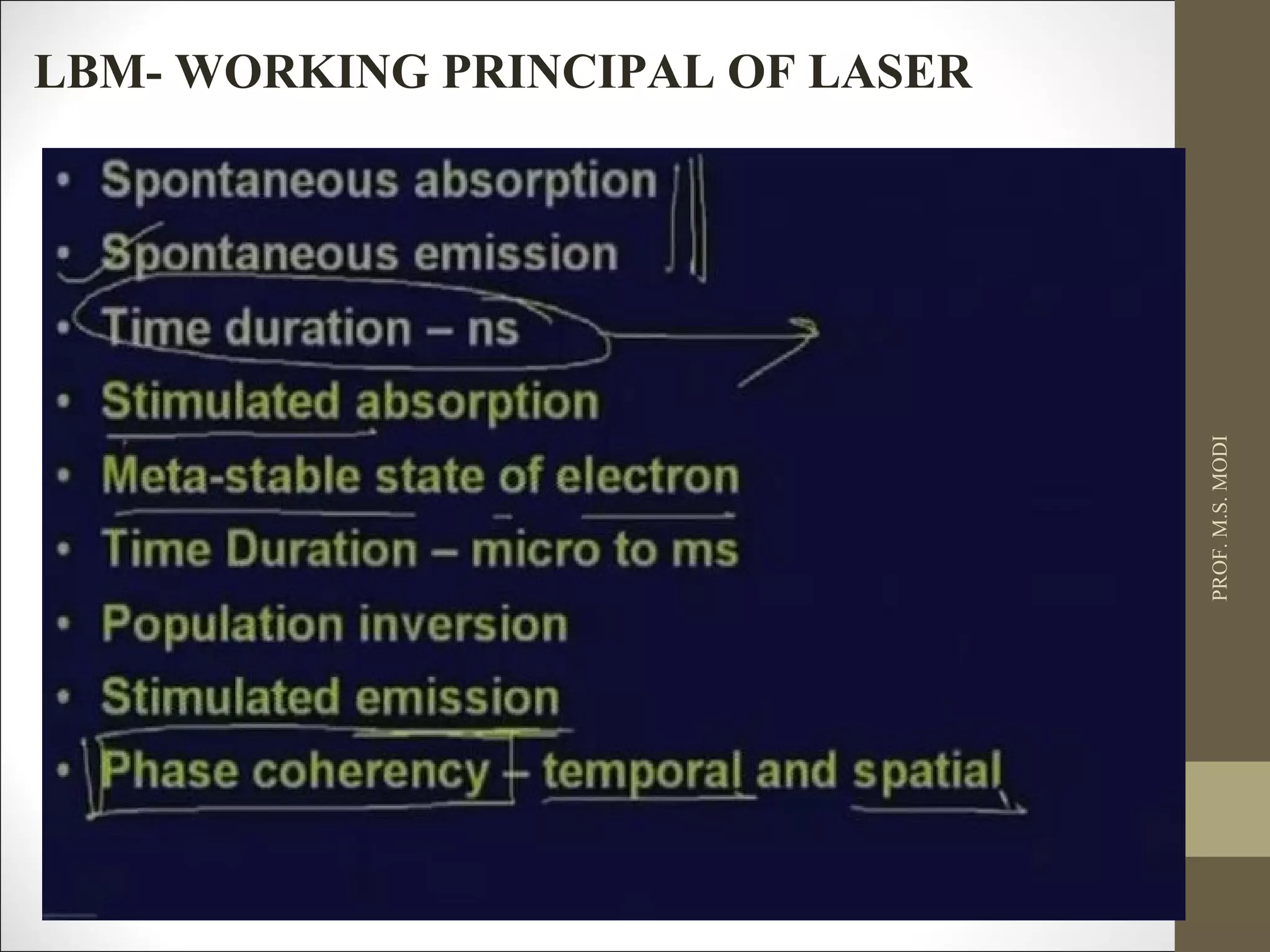
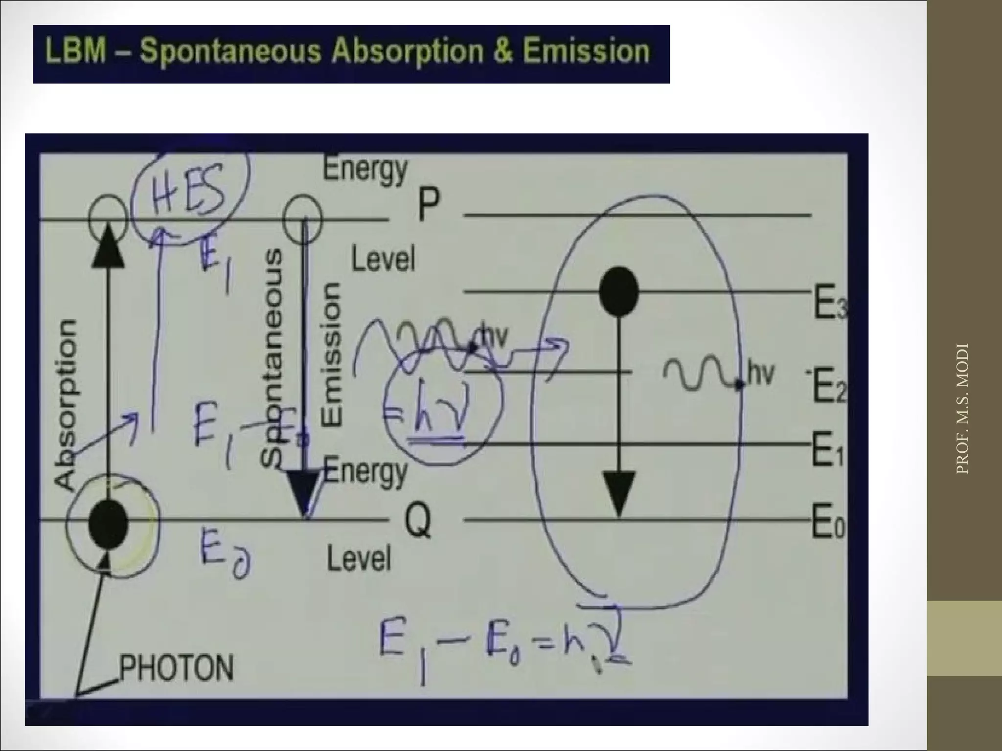
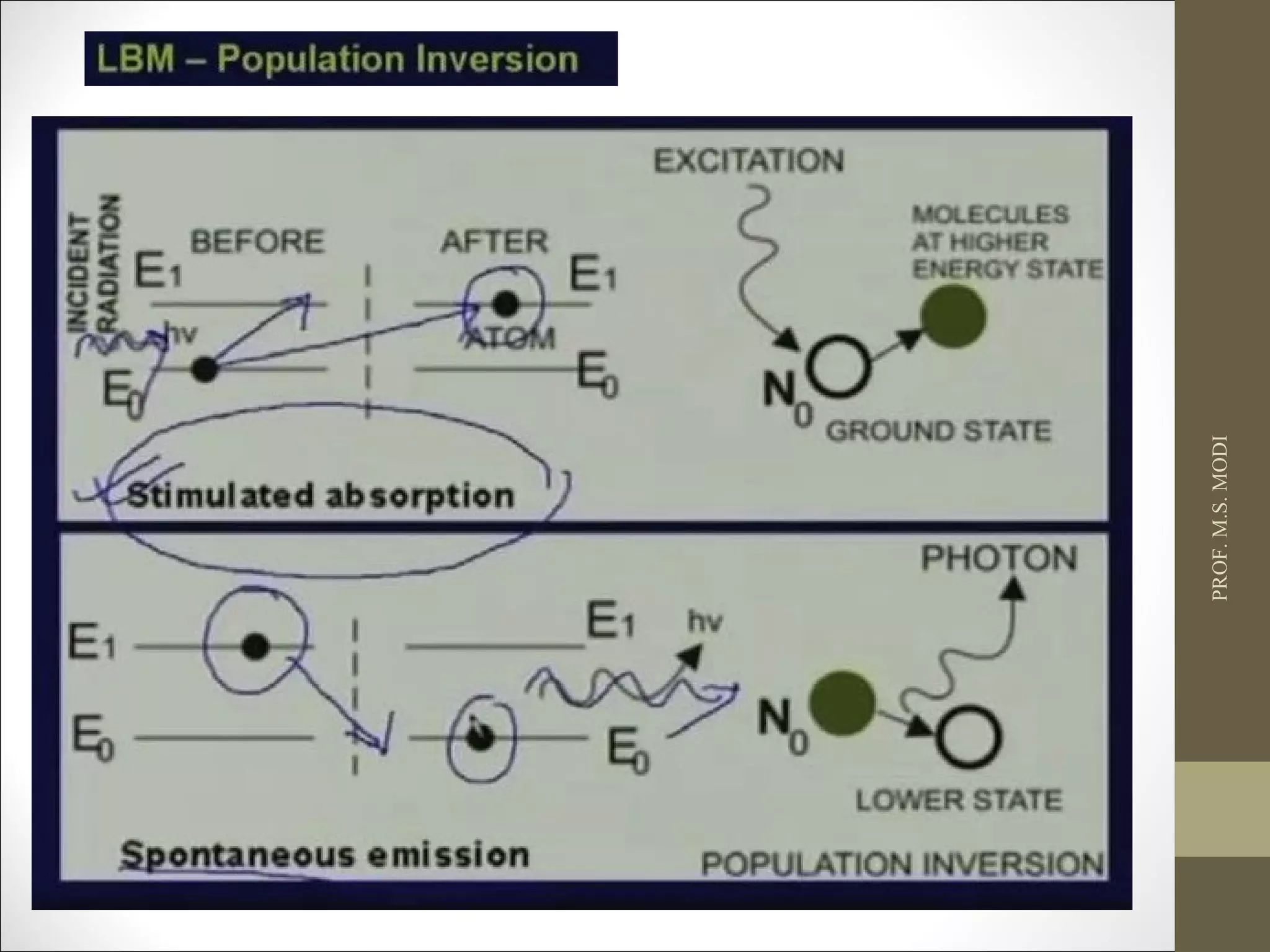
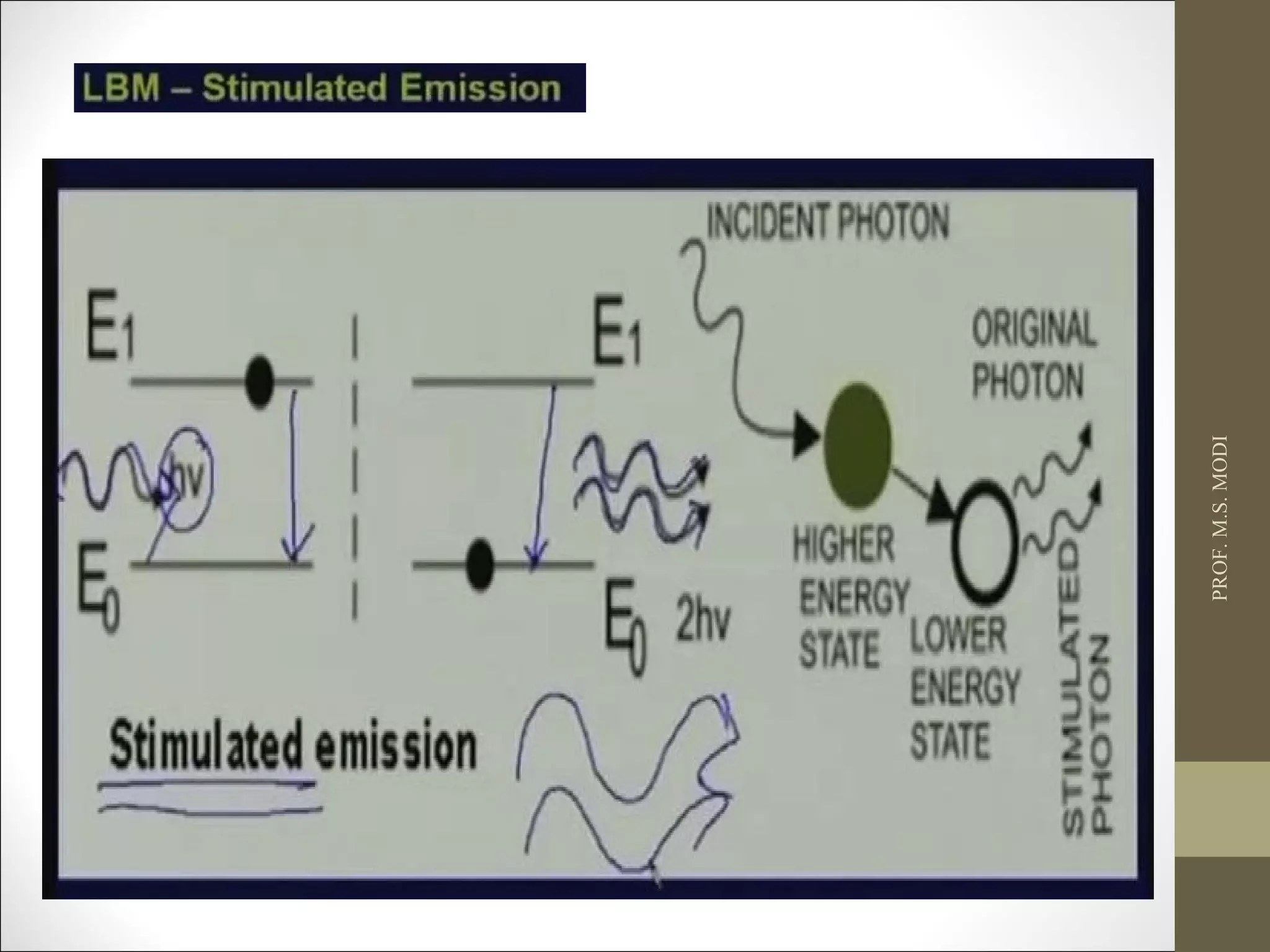
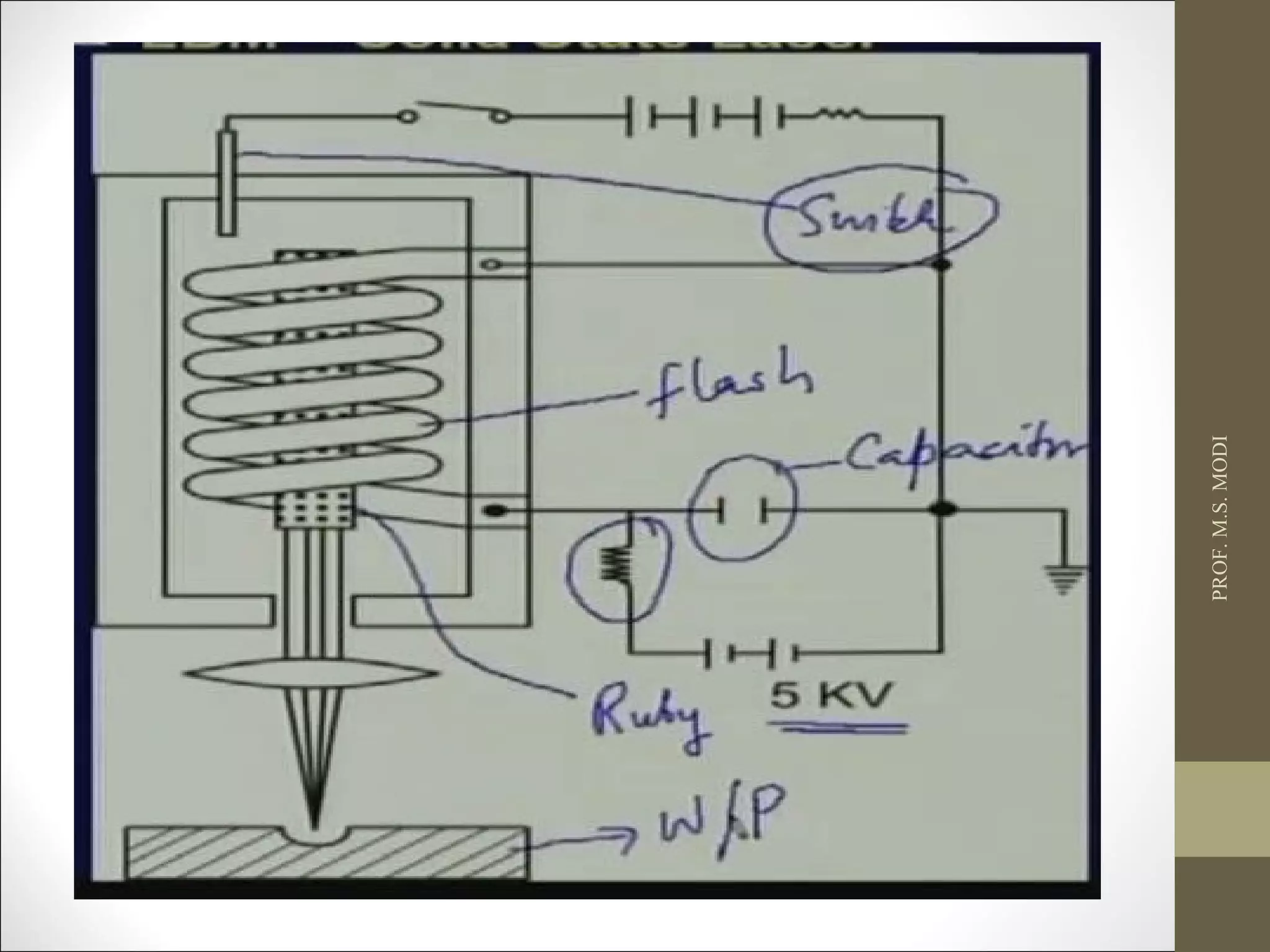
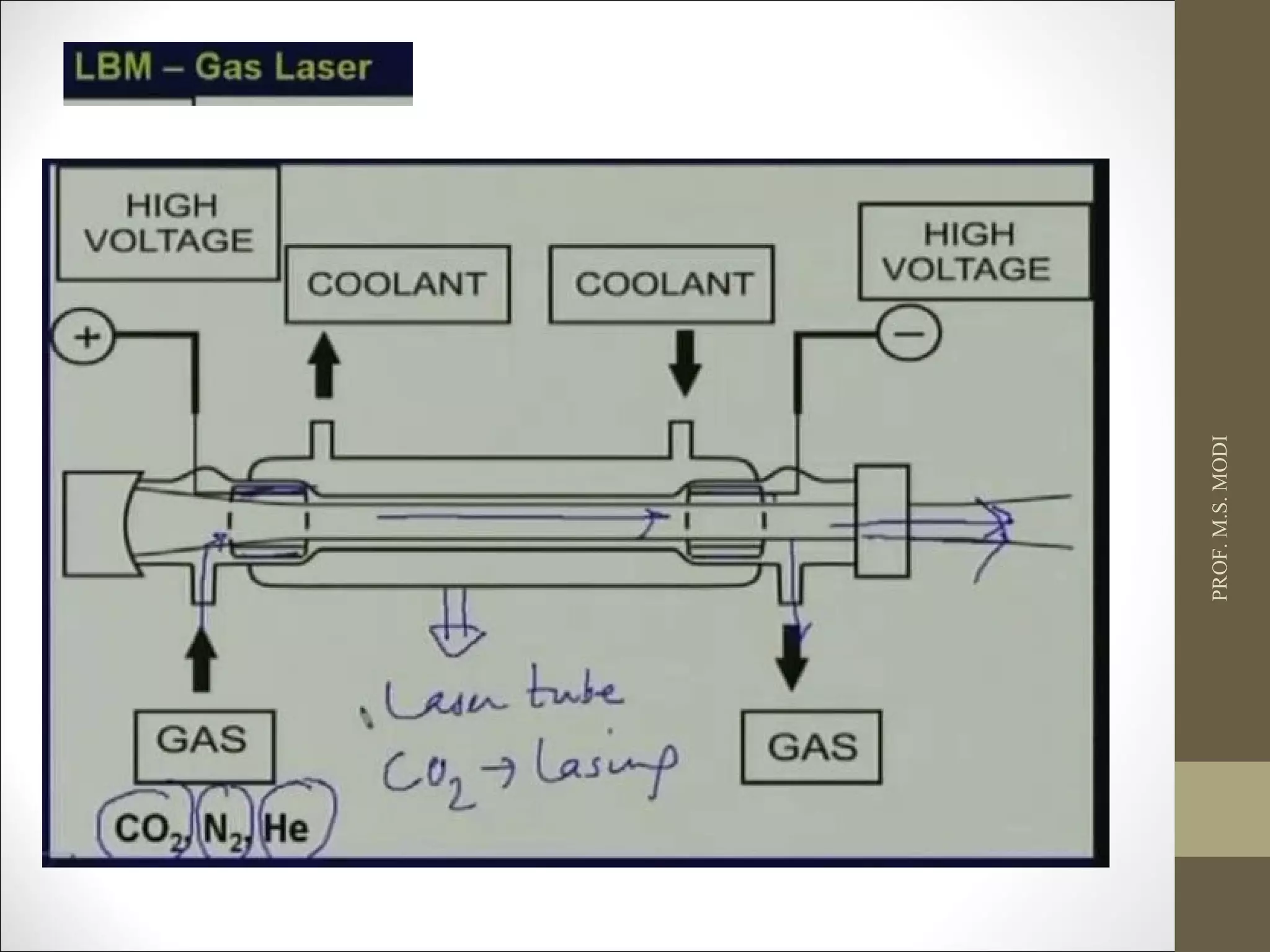
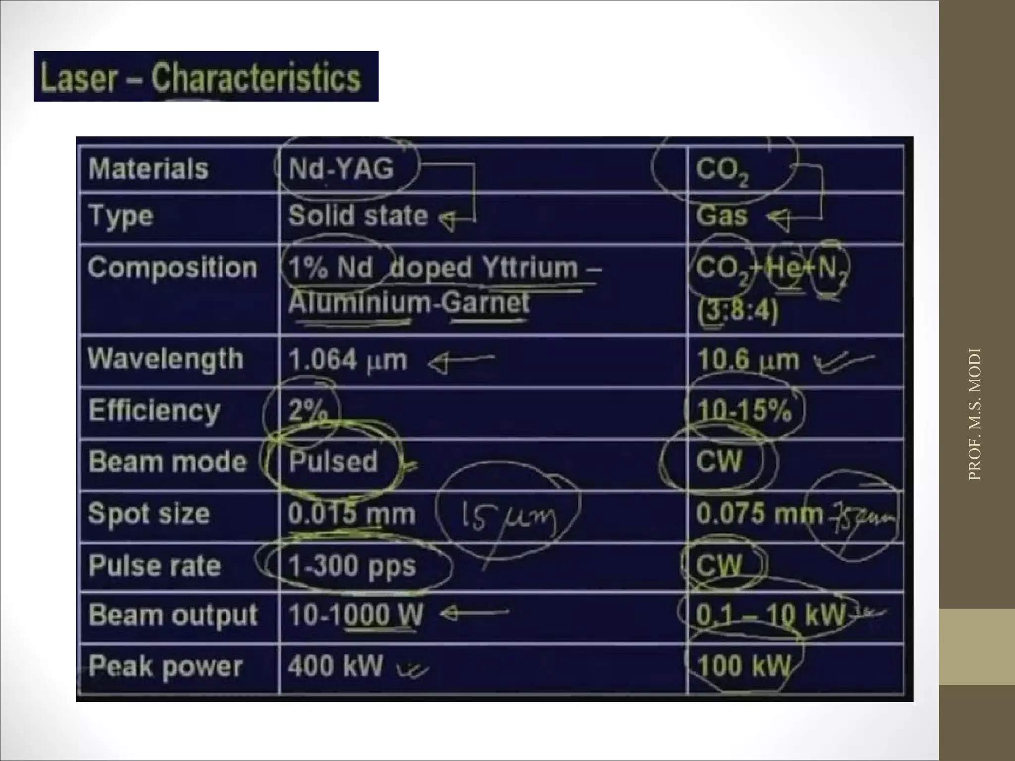
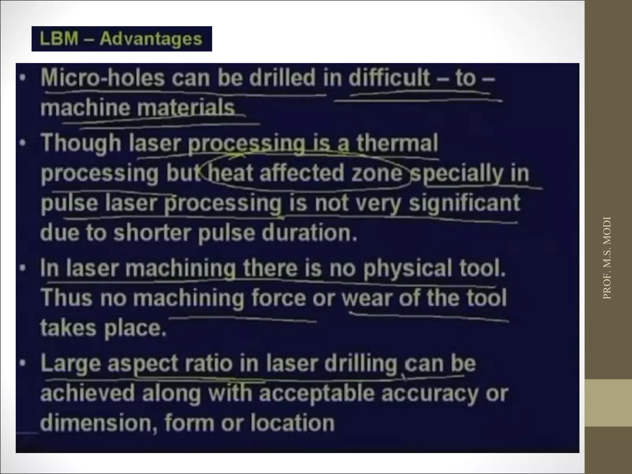
The document discusses various non-traditional machining processes including ultrasonic machining, abrasive jet machining, electrical discharge machining, electrochemical machining, and laser beam machining. It provides descriptions of how each process works, key parameters that affect the processes, and examples of materials and applications where each process is useful. Specifically, it focuses on describing the working principles, advantages, limitations and applications of ultrasonic machining, abrasive jet machining, and electrical discharge machining in more detail.
Electrochemical machining (ECM) is a non-traditional machining process that removes metal by electrolysis rather than mechanical forces. In ECM, a tool acts as a cathode and the workpiece as an anode, and an electric current is passed through an electrolyte in the gap between them, chemically dissolving metal from the workpiece. ECM can machine hard metals and complex shapes more accurately than traditional machining. It provides a smooth surface finish with no mechanical forces or heat affecting the workpiece material. However, ECM requires an electrolyte solution, specialized equipment, and produces chemical waste, making it more expensive and less environmentally friendly than other processes.
The document discusses fixtures used in manufacturing. It defines a fixture as a work-holding or support device used to accurately manufacture duplicate parts while reducing skilled labor requirements. The document outlines key elements of fixtures including locating, clamping, and tool guiding elements. It then classifies common fixtures for milling, welding, drilling, assembly, and gauging. Advantages of fixtures are listed as increased production speed, reduced manpower needs, improved accuracy and conformity while disadvantages include complex design requirements.
This document discusses various forming operations used in sheet metal working. It describes processes like bending, coining, embossing, flanging, hole flanging, beading and curling, ironing, and drawing. For each process, it provides details on how the process works, common applications, advantages and disadvantages. It also discusses considerations for forming die design like part material properties, number of required stampings, and clearance between the punch and die.
This document discusses plasma arc machining (PAM). PAM uses a high-velocity jet of heated gas at around 50,000°C to melt and remove material. Gases are ionized to form plasma which is directed at the workpiece. Key components of PAM systems include a plasma gun, power supply, and cooling mechanisms. PAM can machine hard metals and is used for applications like tube milling, welding specialty alloys, and nuclear pipe systems. Advantages are high production rates and ability to machine hard metals, while disadvantages include high initial costs and inefficient for large cavities. Various PAM types are also described such as conventional, air, and dual-flow systems.
This document provides an overview of friction stir welding (FSW). It describes FSW as a solid-state welding process that uses friction and mechanical stirring to join materials without melting. Key points include: FSW uses a rotating tool to generate frictional heat and plastically deform the materials, leaving a solid phase bond; important parameters are tool rotation/travel speeds and geometry; FSW eliminates issues like porosity and shrinkage seen in fusion welding. Applications include aerospace, transportation, industrial structures, and shipbuilding.
The document discusses various metal forming processes. It describes hot working and cold working of metals, where hot working involves shaping metals above their recrystallization temperature and cold working is below this temperature. Specific metal forming processes covered include forging processes like open die forging, closed die forging, and roll forging. Other forming methods discussed are drawing, extrusion, and bending. The advantages and limitations of hot and cold working are also compared.
The document describes a project report on the design of a common bending tool for two sheet metal components (left and right). It discusses the history of metal shaping tools and introduces press tools and their types like blanking, piercing, bending, etc. It also covers topics like strip layout, types of strip layout arrangements, factors that affect strip arrangement, die design parameters and calculations. The key objectives are to maximize material utilization, reduce production costs, and increase part output through an efficient strip layout and tool design.
This document provides an overview of press working and various sheet metal forming operations. It defines press working as a chipless manufacturing process that uses a press machine to form sheet metal components by applying force. It then describes common sheet metal cutting operations like blanking, punching, trimming, shaving, notching, and shearing. Forming operations like bending and embossing are also summarized. The document aims to introduce students to basic press tool operations for modifying sheet metal geometry.
Design of Stage Progressive Die for a Sheet Metal Component STAY CURIOUS
Progressive die stamping is a metal forming process widely used to produce parts for various industries, such as automotive, electronics and appliances. Progressive die stamping consists of several individual work stations, each of which performs one or more different operations on the part.
This document discusses advanced machining processes, which utilize chemical, electrical, or high-energy beams to machine materials that cannot be processed through traditional machining methods. It describes 10 common types of advanced machining, including chemical machining, electrochemical machining, electrical discharge machining, laser beam machining, electron beam machining, plasma arc cutting, ultrasonic machining, water jet machining, abrasive jet machining, and nanofabrication methods. The document explains the need for these advanced processes and provides examples of typical parts machined through these methods.
Chemical machining or chemical milling uses acidic or alkaline solutions to dissolve materials in a controlled manner for milling or blanking parts. Maskants that are chemically resistant are used to protect surfaces that should not be machined. Etchants like FeCl3 or HNO3 dissolve metals into metallic salts. Process parameters like the selection of etchant and maskant are important. Chemical machining allows for complex contours and hard materials to be machined with a high surface finish and low tooling costs but the process is generally slow. Applications include undercuts, eliminating recast layers, and thinning materials.
Electro-chemical grinding (ECG) is a process that uses both mechanical grinding and electrochemical removal to shape electrically conductive materials. In ECG, a negatively charged grinding wheel with abrasive particles contacts the positively charged workpiece in the presence of an electrolyte fluid. This sets up an electrochemical reaction that dissolves metal from the workpiece, with around 90% of material removed electrochemically and 10% by abrasion. ECG produces very smooth, burr-free surfaces with little heat, making it suitable for grinding fragile or heat-sensitive parts. Applications include shaping tungsten carbide cutting tools, sharpening needles, grinding turbine blades, and removing cracks from steel structures.
Manufacturing Engineering 2, cutting tools and tool holdersGaurav Mistry
Detail study of cutting tool materials, some special materials, carbide tip tools, carbide inserts, types, carbide insert holders, ISO designation of carbide inserts, single point cutting tool nomenclature and angles, tool geometry, Tool life, tool wear and types, machinability
The document describes abrasive flow machining (AFM) and summarizes two research papers on the topic. It defines AFM and discusses different types of AFM machines. The first research paper studies the effect of process variables in AFM and develops models to optimize the process. The second paper examines using AFM to finish difficult-to-machine titanium alloy and finds that boron carbide and silicon carbide abrasives most effectively remove surface imperfections within few cycles. Scanning electron microscopy images show the removal of heat-affected layers on the titanium.
The document discusses drilling and provides objectives about drilling machines. It defines drilling as cutting holes in metal using a drill and rotating motion. It identifies the parts of a drilling machine like the drive, table, and spindle. It describes different types of drills, reamers, and drilling machines. It lists safety precautions like securely clamping the workpiece and using correct drilling speeds.
- Drill bushes are used to guide tools like drills and reamers and are made of hardened steel.
- There are different types of bushes including press fit, removable, and special bushes. Press fit bushes provide long life while guiding tools. Removable bushes like renewable and slip bushes allow for replacement of worn bushes. Special bushes can have unique shapes to prevent tool deflection.
- Drill bushes may have collars to control hole depth or be headless. Renewable bushes are replaced through a liner bush while slip bushes provide quick changeover between operations. Threaded and plate bushes can accommodate closely spaced holes.
This document provides an introduction to electrical discharge machining (EDM). EDM is an unconventional machining process where material is removed by electric sparks between an electrode tool and conductive workpiece, with no direct contact between them. Key aspects of EDM covered include the construction of EDM machines, the role of dielectric fluids, factors that affect the material removal rate such as capacitance and spark parameters, and electrode tool materials and wear characteristics. Graphite, copper, and copper-tungsten are commonly used as tool materials in EDM due to properties like machinability and erosion resistance.
The document provides information about planer machine tools. It describes that planers are used to produce flat surfaces on large workpieces by moving the workpiece past stationary cutting tools. The key parts of a planer are identified as the bed, work table, housings, cross rail, saddles, toolheads, and driving mechanism. Different types of planers are described including double housing, open side, pit, edge, and divided table planers. The document also discusses the drive mechanisms and feed mechanisms used in planers.
Unconventional machining processes remove metal without direct contact between the tool and workpiece. They were developed to address the limitations of conventional machining, such as waste disposal, heat generation, and difficulty machining hard or complex materials. Some unconventional processes include metal forming techniques that shape metals using high energy inputs in short time intervals. Selection of unconventional machining involves considering physical parameters, part shapes, process capabilities, and cost. While unconventional machining enables new applications, it also has limitations such as higher costs and slower speeds than conventional techniques.
Jigs and fixtures are production tools used to accurately manufacture duplicate and interchangeable parts when large numbers are required. Jigs are guiding devices that locate and hold workpieces for machining, while fixtures are holding devices that attach to machines for quick, consistent locating, supporting, and clamping of blanks. Common jig types include plate jigs, box jigs, and indexing jigs. Common fixture types are plate fixtures, angle plate fixtures, and multistation fixtures. The main advantages of using jigs and fixtures are increased productivity, interchangeability of parts, uniform quality, reduced skill requirements, and lower costs.
Fundamentals of Metal cutting and Machining Processes
MACHINING OPERATIONS AND MACHINING TOOLS
Turning and Related Operations
Drilling and Related Operations
Milling
Machining Centers and Turning Centers
Other Machining Operations
High Speed Machining
Electric discharge machining (EDM) is a machining process that uses electrical sparks to erode metals. It works by maintaining a precise gap between an electrode tool and a metal workpiece submerged in a dielectric fluid. Repeated electrical sparks are generated to melt and vaporize small amounts of metal from both the tool and workpiece, allowing complex and hard-to-machine shapes to be produced. EDM can machine metals regardless of hardness and without mechanical force, giving it advantages over traditional machining methods for difficult-to-cut materials.
The document provides an overview of the theory of metal cutting. It discusses the mechanics of chip formation, types of chips, cutting tools and their components/angles. It also describes the metal cutting process, orthogonal vs oblique cutting, thermal aspects of cutting, tool wear and life, factors affecting surface finish and machinability. Cutting fluids, their functions and types are also summarized.
EDM is an electrical discharge machining process that uses electrical sparks to erode materials to shape and cut electrically conductive materials, even very hard metals. It has various applications in industries like molds, dies, aerospace where complex shapes are required. While EDM allows machining hard metals and complex shapes, it has slow material removal rates and high power consumption compared to traditional machining.
This seminar report discusses the hydroforming process. Hydroforming uses liquid pressure to form complex metal shapes. There are two types: tube hydroforming forms tubing, while sheet hydroforming forms sheet metal. Hydroforming offers advantages over conventional forming like reduced weight, fewer parts, and tighter tolerances. It is increasingly used in automotive and aerospace industries. The report provides details on the different hydroforming techniques, design considerations, materials used, and economics of hydroforming.
Metal forming processes are used to shape metals into useful products. Rolling is the most common forming process and accounts for around 90% of metal forming. It involves passing metal between rolls to reduce thickness or change cross-section. Forging uses dies and compression to shape hot or cold metal. Extrusion forces heated metal through a die to create shapes like rods, tubes and structural sections. Drawing pulls metal through a die to make wires, rods and tubes from both hot and cold workpieces. Deep drawing specifically makes cylindrical parts like cups from sheet metal.
The document provides an overview of metal cutting principles and processes. It discusses:
- The fundamentals of metal cutting including chip formation and common cutting processes like turning, milling, and cutting-off.
- Key variables that influence the cutting process like cutting speed, feed, depth of cut, tool material, and workpiece material.
- Different tool geometries including single-point and multi-point tools as well as tool nomenclature systems.
- The mechanics of chip formation involving shear deformation along the shear plane as material is removed.
- The two main methods of metal cutting - orthogonal and oblique cutting.
The document discusses various non-traditional machining processes including chemical machining, electrochemical machining, electrical discharge machining, laser beam machining, electron beam machining, water jet machining, abrasive jet machining, and ultrasonic machining. These processes are used for hard materials, complex shapes, or where heat and stresses from traditional machining would cause damage. Each process removes material in unique ways such as through chemical dissolution, electrochemical erosion, electrical sparks, focused light/electron beams, or abrasive particle impact.
The document discusses various traditional and nontraditional machining processes. It describes grinding as a traditional machining process that uses abrasive particles to remove small amounts of metal. It then discusses several nontraditional processes including chemical machining, electrochemical machining, electrical discharge machining, laser beam machining, electron beam machining, water jet machining, abrasive jet machining, and ultrasonic machining. Each of these processes removes material using methods other than traditional cutting, such as through chemical or electrical erosion, melting with lasers or electrons, or erosion with high-pressure water or abrasive particles. The document provides details on the mechanisms and applications of each of these nontraditional machining methods
Non Traditional Machining is playing vital role in now a days in mechanical Industries so student it should be need sound knowledge in this particular subject due to impact of this subject i am prepare in this materials it is most useful for my students...
All The Best ...
By: Author-Prof.S.Sathishkumar
This document outlines several non-traditional machining processes including ultrasonic machining, abrasive water jet machining, chemical machining, electro-chemical machining, electro-chemical grinding, electrodischarge machining, and laser beam machining. It provides brief descriptions of each process and examples of their applications. Case studies are presented comparing different processes such as CNC milling, wire EDM, and die sinker EDM for specific part geometries. Overall comparisons of machining tolerances and surface roughness between different processes are also discussed.
Non-traditional machining processes like EDM, ECM, laser beam machining and waterjet machining were developed to machine materials that cannot be processed through traditional methods due to limitations such as high hardness, complex shapes, or thin/delicate parts. EDM works by eroding metals using electrical sparks between an electrode tool and workpiece, allowing complex shapes to be machined. Laser beam machining uses a focused high-energy laser beam to drill, cut or mark materials. Waterjet machining directs a high-velocity water jet, sometimes with abrasives added, to cut through materials using the force of the water. These advanced processes enable machining of materials and shapes not possible through traditional methods.
The document discusses various thermal energy-based material removal techniques, focusing on electrical discharge machining (EDM) and wire EDM. EDM works by using electrical sparks to erode metals, with the sparks controlled by a power supply. Wire EDM uses a continuously moving wire to remove material through controlled repetitive sparks in a dielectric fluid. Both processes can machine hard materials and leave minimal burrs. The document also covers laser beam machining, which uses a focused laser beam to melt, vaporize, or ablate material.
The document discusses non-traditional machining processes. It defines these processes as those that remove material using techniques involving mechanical, thermal, electrical or chemical energy rather than traditional sharp cutting tools. The document outlines the key characteristics of non-traditional machining, provides examples of different types of processes classified by energy type used, and discusses specific processes like abrasive jet machining and ultrasonic machining in more detail.
This document provides an overview of the manufacturing technology course ME-202 on nontraditional machining processes. The document discusses several advanced machining processes including electrical discharge machining (EDM), electrochemical machining (ECM), laser beam machining (LBM), electron beam machining (EBM). For each process, the document outlines the basic principles, mechanisms of material removal, advantages, limitations and applications. Examples are given of parts made using these advanced processes such as turbine blades, fuel injection nozzles, and knee implants.
The document discusses non-conventional machining processes. It begins by distinguishing between conventional machining processes, which use hard cutting tools to remove material, and non-conventional processes, which use other energies like mechanical, thermal, electrical, or chemical. Non-conventional processes are then classified based on the type of energy used, including mechanical, electrochemical, electro-thermal, and chemical processes. Examples of specific non-conventional machining techniques are provided within each classification.
NTMM for GATE IES PSUs 2023 by S K Mondal.pdfRamMishra65
1. Electrochemical machining (ECM) is a non-traditional machining process that involves removing metal by anodic dissolution using a high-amperage electrical current passed through an electrolyte.
2. In ECM, the workpiece acts as an anode and is placed close to a cathode tool, with an electrolyte flowing between them. Metal dissolves from the workpiece and is carried away by the electrolyte.
3. ECM can machine very hard metals and produce complex shapes with a high material removal rate and excellent surface finish without thermal or mechanical damage. However, it requires expensive equipment and the electrolyte is corrosive.
The document discusses various thermal energy-based material removal techniques, focusing on electrical discharge machining (EDM) and laser beam machining (LBM). It provides details on the EDM and LBM processes, including how they work, common applications, advantages, and limitations. EDM uses electric sparks to melt and vaporize material, while LBM uses a focused laser beam. Both processes precisely shape materials by thermal heating without mechanical forces.
The document discusses conventional and unconventional machining processes. Conventional machining involves direct contact between the tool and workpiece and removal of metal through chip formation, which produces chips as waste. Unconventional processes do not require direct contact and instead use various forms of energy like thermal, electrical or electrochemical to remove metal. Common unconventional processes described include EDM, ECM, laser beam machining and water jet machining. The document also covers CNC machines and how part programs control automated machining through coded G and M commands.
This document provides an overview of unconventional machining processes. It begins with an introduction to conventional machining processes and then discusses the need for unconventional processes to machine advanced materials. The document categorizes unconventional processes as mechanical, electrical, chemical/electrochemical, or thermal based. Specific unconventional processes like ultrasonic machining and abrasive water jet cutting are then described in more detail.
Non-traditional machining processes are used to manufacture complex precision parts. They use indirect energy like sparks, lasers, heat or chemicals instead of direct tool contact. This allows machining of hard materials with complex shapes. Some common non-traditional processes include electrical discharge machining (EDM), electrochemical machining (ECM), laser beam machining, and abrasive jet machining. These processes remove material using techniques like electrical sparks, electrolysis, focused laser beams or high pressure abrasive jets. Non-traditional machining provides benefits like high accuracy, improved surface finish, less tool wear and greater design flexibility compared to traditional machining.
This document provides an overview of ultrasonic machining (USM). It explains that in USM, a tool oscillated at ultrasonic frequencies (around 20 kHz) with abrasive particles in the gap between the tool and workpiece. The abrasive particles are forced to repeatedly impact the work surface due to the ultrasonic oscillations, removing material through micro-chipping. Key advantages of USM include the ability to machine hard and brittle materials precisely without producing thermal or chemical defects, while disadvantages include low material removal rates and fast tool wear. Common abrasives used include aluminum oxide and silicon carbide in a water slurry. USM is suitable for machining intricate shapes, small holes, and hard non-conductive
This document provides information on various unconventional machining processes. It begins by classifying these processes into categories based on the type of energy used, including mechanical, electrical, thermal, and chemical. Specific processes discussed include ultrasonic machining, water jet cutting, abrasive jet machining, electrochemical machining, electric discharge machining, and chemical machining. Key aspects like principles of operation, equipment, process variables, applications, and limitations are summarized for each process.
The document discusses various thermal energy-based material removal techniques, including electrical discharge machining (EDM) and laser beam machining (LBM). It provides details on the EDM process, including how it works using electric sparks to erode metals. Wire EDM and micro EDM are also examined. The document then covers the LBM process, the types of lasers used for different applications like cutting, drilling, and marking. It discusses key laser beam parameters such as beam waist, intensity, and depth of focus. In summary, the document provides an in-depth overview of EDM and LBM processes for removing material using thermal energy.
This document discusses nontraditional manufacturing processes. It provides an overview of ultrasonic machining (USM), describing the process, material removal mechanism, advantages, disadvantages, and applications. It also summarizes waterjet machining (WJM) and abrasive waterjet machining (AWJM), explaining the principles, advantages, disadvantages, and applications of these processes. Finally, it briefly introduces abrasive jet machining (AJM), describing the basic process and its uses.
Similar to Non convention machining process,Advanced Machining Process,Production Technology (20)
1. The diesel cycle model assumes air is the working substance with constant specific heats. It is taken into the cylinder during the suction stroke at constant pressure and compressed adiabatically.
2. Heat is added at constant pressure, causing the substance to expand adiabatically in the cylinder. It then drops instantly to atmospheric pressure at constant volume.
3. The efficiency of the theoretical diesel cycle depends on the compression ratio, cut-off ratio, and specific heat ratio. Higher compression ratios increase efficiency up to the point of pre-ignition.
The document discusses broaching and sawing manufacturing processes. It defines broaching as removing metal with a row of teeth on a tool, where each tooth removes more material. Broaching can produce both internal and external features to tight tolerances. It then covers broaching tool design, chip formation mechanics, heat generation, advantages and disadvantages, and different broaching machines and methods of operation. The document also classifies different types of sawing machines like reciprocating, circular, and band saws and discusses saw blade terminology and tooth forms.
World class manufacturing is a collection of concepts that set production standards for organizations to follow. It originated from Japanese manufacturing practices and focuses on process-driven techniques like just-in-time production, streamlined flow, small lot sizes, and zero defects. The goals of world class manufacturing include improving safety, quality, cost, delivery times, and environmental impact. It utilizes principles like just-in-time, total quality management, total productive maintenance, lean manufacturing, agile manufacturing, and concurrent engineering. Agile manufacturing allows organizations to quickly respond to customer needs and market changes while controlling costs and quality.
Total Productive Maintenance (TPM) is a method for improving equipment effectiveness through employee involvement. It originated in Japan in 1971 as a way to improve machine availability and reduce waste. TPM involves management, operators, and maintenance working together to ensure overall equipment effectiveness. The key pillars of TPM include 5S, autonomous maintenance by operators, continuous improvement activities, planned predictive maintenance, quality maintenance, training, and safety/environmental practices. TPM is implemented in stages, starting with preparation, then introduction, implementation involving the eight pillars, and finally institutionalization so that TPM becomes the organizational culture.
This document provides an overview of Just-In-Time (JIT) manufacturing. It defines JIT as a method that organizes production so that parts are available when needed. The key aspects of JIT discussed include: eliminating waste through continuous improvement, leveling production using a pull system like Kanban, setting up cells/modules, reducing setup times, and ensuring quality from suppliers. JIT aims to provide customers what they want, when they want it, with no excess inventory or waste.
Benchmarking is the process of comparing business processes and performance metrics to industry best practices in order to improve performance. It involves identifying top performers in other organizations, understanding what makes them successful, and adapting practices for one's own organization. The key advantages are improved processes and products, reduced costs and time, and a more competitive strategy. While benchmarking has helped many organizations, there are also risks if benchmarks are not well-defined or comparisons are incorrect. The typical benchmarking process involves planning, analysis, integration, action, and recalibrating benchmarks over time. There are different types of benchmarking based on what is compared (e.g. products, processes) and who is compared against (e.g. internal/external
Six Sigma is a data-driven methodology for improving processes by reducing variability and minimizing defects. It aims for near perfection by targeting no more than 3.4 defects per million opportunities. The Six Sigma methodology includes DMAIC (Define, Measure, Analyze, Improve, Control) for improving existing processes and DMADV (Define, Measure, Analyze, Design, Verify) for developing new processes. Key roles include Champions, Master Black Belts, Black Belts and Green Belts who lead Six Sigma projects and use statistical tools to drive process improvement. Implementing Six Sigma helps companies better meet customer expectations, accelerate improvement rates, and enhance business performance and value.
The document discusses different types of drilling machines. It describes portable, sensitive, upright, radial, gang, and deep hole drilling machines. It provides details on the typical parts of drilling machines like the base, column, table, head, spindle, and feed mechanisms. It also explains twist drills, reamers, counterbores, and taps used with drilling machines.
This document provides an overview of different types of pumps. It begins by defining a pump as a mechanical device that conveys liquid from one place to another by adding energy. Pumps are classified as either positive displacement pumps, which include reciprocating, gear, vane and screw pumps, or centrifugal pumps, which include single-stage, multi-stage, axial and mixed flow pumps. Key concepts discussed include pump components, classifications, operating principles, calculations and comparisons between reciprocating and centrifugal pumps. Terminology such as head, discharge and efficiency are also defined.
Gear finishing processes are necessary to produce accurate, smooth gear teeth after initial formation. The main gear finishing processes are gear shaving, burnishing, grinding, lapping, and honing. Gear shaving involves running a gear against a cutter to scrape off irregularities. Gear burnishing plastically moves excess material during rolling. Gear grinding is the most accurate but also the most expensive method. Lapping and honing use abrasives to remove burrs and irregularities from heat treated gears in a faster process than other methods.
The document discusses various heat treatment processes used to alter the properties of metals and alloys. It describes processes like normalizing, annealing, hardening, and tempering. Normalizing involves heating above the critical temperature and air cooling to refine grains. Annealing fully softens metals by heating above the critical temperature and slow cooling. Hardening involves heating above the critical temperature and quenching in water or oil to form martensite. Tempering reduces the brittleness of hardened steel by reheating below the critical temperature.
Drilling jigs are used to accurately locate and hold workpieces for drilling and other machining operations. There are various types of drilling jigs defined by their shape, construction method, and how they locate and support the workpiece. The most common types include template jigs, plate jigs, channel jigs, diameter jigs, solid jigs, and post jigs. Drilling jigs provide accuracy and repeatability for drilling multiple holes in production environments.
Powder metallurgy is a process for manufacturing parts from metal powders by compacting and sintering. Key steps include producing metal powders through methods like atomization or chemical reduction, blending powders and lubricants, compacting the blended powder in a die under pressure to form a green compact, and sintering the compact at high temperatures to bond the powder particles. The sintered parts have properties that cannot be achieved through conventional manufacturing and the process allows for high precision and low waste production of simple parts.
Comparators are used to compare measurements and dimensions. There are several types of comparators including mechanical, optical, electric, electronic, and pneumatic. Mechanical-optical comparators use both mechanical and optical systems to magnify small variations in measurements. Electrical comparators have no moving parts and allow remote measurement indication. Pneumatic comparators measure differences in air pressure caused by variations in airflow through an orifice to determine dimensions. Each type has advantages like accuracy, remote sensing, and simplicity, as well as disadvantages like measurement limitations, required power sources, and sensitivity to environmental factors.
The document discusses various metal joining processes including welding. It begins by defining welding and outlining the key principles of heat and pressure used to join metals. The document then categorizes and describes different types of arc welding processes like metal arc welding, flux-cored arc welding, gas tungsten arc welding, and gas metal arc welding. It also covers gas welding processes like oxy-acetylene welding and discusses terminology, applications, advantages, and limitations of welding.
introduction to Mechanical Measurement and Metrology.Prof.Mayur Modi
This document discusses various concepts related to measurement in mechanical engineering. It defines key terms like accuracy, precision, linearity, sensitivity, readability, calibration, repeatability, reproducibility, and sources of error in measurement. Accuracy refers to how close a measurement is to the true value, while precision refers to the consistency of repeated measurements. Errors can arise from reading errors, characteristics of the measuring instrument, environmental factors, loading effects, and dynamic influences. Proper measurement requires selecting an appropriate method and standard, and accounting for various error sources.
Electric vehicle and photovoltaic advanced roles in enhancing the financial p...IJECEIAES
Climate change's impact on the planet forced the United Nations and governments to promote green energies and electric transportation. The deployments of photovoltaic (PV) and electric vehicle (EV) systems gained stronger momentum due to their numerous advantages over fossil fuel types. The advantages go beyond sustainability to reach financial support and stability. The work in this paper introduces the hybrid system between PV and EV to support industrial and commercial plants. This paper covers the theoretical framework of the proposed hybrid system including the required equation to complete the cost analysis when PV and EV are present. In addition, the proposed design diagram which sets the priorities and requirements of the system is presented. The proposed approach allows setup to advance their power stability, especially during power outages. The presented information supports researchers and plant owners to complete the necessary analysis while promoting the deployment of clean energy. The result of a case study that represents a dairy milk farmer supports the theoretical works and highlights its advanced benefits to existing plants. The short return on investment of the proposed approach supports the paper's novelty approach for the sustainable electrical system. In addition, the proposed system allows for an isolated power setup without the need for a transmission line which enhances the safety of the electrical network
Applications of artificial Intelligence in Mechanical Engineering.pdfAtif Razi
Historically, mechanical engineering has relied heavily on human expertise and empirical methods to solve complex problems. With the introduction of computer-aided design (CAD) and finite element analysis (FEA), the field took its first steps towards digitization. These tools allowed engineers to simulate and analyze mechanical systems with greater accuracy and efficiency. However, the sheer volume of data generated by modern engineering systems and the increasing complexity of these systems have necessitated more advanced analytical tools, paving the way for AI.
AI offers the capability to process vast amounts of data, identify patterns, and make predictions with a level of speed and accuracy unattainable by traditional methods. This has profound implications for mechanical engineering, enabling more efficient design processes, predictive maintenance strategies, and optimized manufacturing operations. AI-driven tools can learn from historical data, adapt to new information, and continuously improve their performance, making them invaluable in tackling the multifaceted challenges of modern mechanical engineering.
Comparative analysis between traditional aquaponics and reconstructed aquapon...bijceesjournal
The aquaponic system of planting is a method that does not require soil usage. It is a method that only needs water, fish, lava rocks (a substitute for soil), and plants. Aquaponic systems are sustainable and environmentally friendly. Its use not only helps to plant in small spaces but also helps reduce artificial chemical use and minimizes excess water use, as aquaponics consumes 90% less water than soil-based gardening. The study applied a descriptive and experimental design to assess and compare conventional and reconstructed aquaponic methods for reproducing tomatoes. The researchers created an observation checklist to determine the significant factors of the study. The study aims to determine the significant difference between traditional aquaponics and reconstructed aquaponics systems propagating tomatoes in terms of height, weight, girth, and number of fruits. The reconstructed aquaponics system’s higher growth yield results in a much more nourished crop than the traditional aquaponics system. It is superior in its number of fruits, height, weight, and girth measurement. Moreover, the reconstructed aquaponics system is proven to eliminate all the hindrances present in the traditional aquaponics system, which are overcrowding of fish, algae growth, pest problems, contaminated water, and dead fish.
Advanced control scheme of doubly fed induction generator for wind turbine us...IJECEIAES
This paper describes a speed control device for generating electrical energy on an electricity network based on the doubly fed induction generator (DFIG) used for wind power conversion systems. At first, a double-fed induction generator model was constructed. A control law is formulated to govern the flow of energy between the stator of a DFIG and the energy network using three types of controllers: proportional integral (PI), sliding mode controller (SMC) and second order sliding mode controller (SOSMC). Their different results in terms of power reference tracking, reaction to unexpected speed fluctuations, sensitivity to perturbations, and resilience against machine parameter alterations are compared. MATLAB/Simulink was used to conduct the simulations for the preceding study. Multiple simulations have shown very satisfying results, and the investigations demonstrate the efficacy and power-enhancing capabilities of the suggested control system.
artificial intelligence and data science contents.pptxGauravCar
What is artificial intelligence? Artificial intelligence is the ability of a computer or computer-controlled robot to perform tasks that are commonly associated with the intellectual processes characteristic of humans, such as the ability to reason.
› ...
Artificial intelligence (AI) | Definitio
Batteries -Introduction – Types of Batteries – discharging and charging of battery - characteristics of battery –battery rating- various tests on battery- – Primary battery: silver button cell- Secondary battery :Ni-Cd battery-modern battery: lithium ion battery-maintenance of batteries-choices of batteries for electric vehicle applications.
Fuel Cells: Introduction- importance and classification of fuel cells - description, principle, components, applications of fuel cells: H2-O2 fuel cell, alkaline fuel cell, molten carbonate fuel cell and direct methanol fuel cells.
Embedded machine learning-based road conditions and driving behavior monitoringIJECEIAES
Car accident rates have increased in recent years, resulting in losses in human lives, properties, and other financial costs. An embedded machine learning-based system is developed to address this critical issue. The system can monitor road conditions, detect driving patterns, and identify aggressive driving behaviors. The system is based on neural networks trained on a comprehensive dataset of driving events, driving styles, and road conditions. The system effectively detects potential risks and helps mitigate the frequency and impact of accidents. The primary goal is to ensure the safety of drivers and vehicles. Collecting data involved gathering information on three key road events: normal street and normal drive, speed bumps, circular yellow speed bumps, and three aggressive driving actions: sudden start, sudden stop, and sudden entry. The gathered data is processed and analyzed using a machine learning system designed for limited power and memory devices. The developed system resulted in 91.9% accuracy, 93.6% precision, and 92% recall. The achieved inference time on an Arduino Nano 33 BLE Sense with a 32-bit CPU running at 64 MHz is 34 ms and requires 2.6 kB peak RAM and 139.9 kB program flash memory, making it suitable for resource-constrained embedded systems.
Non convention machining process,Advanced Machining Process,Production Technology
1. PROF. MAYUR S MODI
Assistant Professor
Mechanical Engineering Department
SSASIT, Surat
Non-conventionalNon-conventional
Machining ProcessMachining Process
Production technology
(181903)
PROF.M.S.MODI
2. Introduction
• In recent years a number of new material have
been developed which are being commonly used
in space research missiles and nuclear industry.
• These materials are stronger, harder, tougher,
heat and wear resistant and cannot be machined
by this conventional machining process.
• These difficulties of conventional machining
process are solved by this process.
• It is new metal removing process called newer
machining process or unconventional machining
process.
PROF.M.S.MODI
5. A machining process is called non-traditional if
its material removal mechanism is basically
different than those in the traditional processes,
i.e. a different form of energy (other than the
excessive forces exercised by a tool, which is in
physical contact with the work piece) is applied
to remove the excess material from the work
surface, or to separate the work piece into
smaller parts.
PROF.M.S.MODI
8. Non-traditional processes generally should be
employed when
1.There is a need to process some newly developed
difficult to- cut materials, machining of which is
accompanied by excessive cutting forces and tool wear;
2.There is a need for unusual and complex shapes, which
cannot easily be machined or cannot at all be machined
by traditional processes;
PROF.M.S.MODI
12. Ultrasonic Machining
• Process principle, process parameters and their
Applications
• Utilizes mechanical energy for material removal by
erosion - for conducting and non-conducting materials.
PROF.M.S.MODI
14. •The acoustic head is the most
complicated part of the machine. It
must provide a static constant
force, as well as the high frequency
vibration.
•Tools are produced of tough but
ductile metals such as soft steel of
stainless steel.
•Aluminum and brass tools wear
near 5 to 10 times faster.
•Abrasive slurry consists of a mixture of liquid (water is the most
common but oils or glycerol are also used) and 20% to 60% of
abrasives with typical grit sizes of 100 to 800. The common types
of abrasive materials are boron carbide, silicon carbide, diamond,
and corundum (Al2O3).
PROF.M.S.MODI
16. Applications
• The ultrasonic machining process can be used to
cut through and blind holes of round or irregular
cross-sections.
• The process is best suited to poorly conducting,
hard and brittle materials like glass, ceramics,
carbides, and semiconductors.
PROF.M.S.MODI
18. Process Parameters
The critical parameters to control the process are
• Tool frequency,
• Amplitude and material,
• Abrasive grit size(200-400 for rough and 800-
1000 for finished) and material,
• Feed force,(Tool amplitude 0.01 -0.06 mm)
• Slurry concentration(20-60 % by volume of the
abrasives)
• Viscosity.
PROF.M.S.MODI
19. BE SEM-VIII Examination
May 2012
• Describe Ultrasonic Machining (USM) process with neat
sketch. Discuss how the following factors effects the material
removal rate of USM. (7 Marks)
• (i) Grain Size (iv) Feed force
• (ii) Frequency (v) Hardness ratio
• (iii) Amplitude (vi) Abrasive concentration
PROF.M.S.MODI
21. Introduction
• Abrasive jet cutting machines which are used to
cut sheet materials or to remove materials of
work piece from a surface by generating a
focused stream of fluid mixed with abrasive
particles.
• Abrasive jet cutting machines includes four main
types of devices abrasive water jet cutters, air
abrasive jet cutters, and precision blaster or
micro-jets.
• They are used for drilling, detailing and precision
cutting of printed circuit boards and other high
quality components.
PROF.M.S.MODI
24. • The high pressure air/gas entrains the abrasive particles
and this mixture emerges from a small nozzle at high
velocity.
• This stream of abrasive particles strikes the work piece at
nearly the speed of sound and cuts the material
PROF.M.S.MODI
25. The process parameters are listed
below:
• Abrasive
1.Material – Al2O3/ SiC / glass beads
2.Shape – irregular / spherical
3.Size – 10 ~ 50 μm
4.Mass flow rate – 2 ~ 20 gm/min
• Carrier gas
1.Composition – Air, CO2, N2
2.Density – Air ~ 1.3 kg/m3
3.Velocity – 500 ~ 700 m/s
4.Pressure – 2 ~ 10 bar
5.Flow rate – 5 ~ 30 lpm
PROF.M.S.MODI
26. • Abrasive Jet
1.Velocity – 100 ~ 300 m/s
2.Mixing ratio – mass flow ratio of abrasive to gas =
3.Stand-off distance – 0.5 ~ 5 mm
4.Impingement Angle – 60 ~ 90
• Nozzle
1.Material –sapphire
2.Diameter – (Internal) 0.2 ~ 0.8 mm
3.Life – 10 ~ 300 hours
PROF.M.S.MODI
27. Advantages
• Ability to cut brittle or heat sensitive material without
damage.
• Ability to cut intricate holes in material of any hardness.
• Low capital cost.
• Surface finish obtain is good.
• Virtually no heat is generated in the work piece
PROF.M.S.MODI
28. Disadvantages
• Slow material removal rate.
• Stray cutting and hence accuracy is not good.
• Abrasive powder cannot be reused.
• Embedding of abrasive in the work piece.
• A suitable dust collecting system is required.
PROF.M.S.MODI
29. Applications
• Cleaning purpose.
• Cutting fine lines.
• Machining semiconductors.
• Drilling and cutting thin section of hardened metal.
• Removing plating, anodic or, thermal oxide coating
• Cutting and etching, quartz, mica etc.
PROF.M.S.MODI
31. Objectives
• Describe the basic working principle of EDM process
• Draw schematically the basics of EDM
• Describe spark initiation in EDM
• Describe material removal mechanism in EDM
• Identify the process parameters in EDM
• Describe the characteristics of EDM
• Identify the purpose of dielectric fluid in EDM
• Analyse the required properties of EDM tool
• List four common tool material for EDM
• Develop models for material removal rate in EDM
PROF.M.S.MODI
32. Introduction
• Electro Discharge Machining (EDM) is an
electro-thermal non-traditional machining
process, where electrical energy is used to
generate electrical spark and material removal
mainly occurs due to thermal energy of the spark.
• EDM is mainly used to machine difficult-to-
machine materials and high strength temperature
resistant alloys.
• EDM can be used to machine difficult geometries
in small batches or even on job-shop basis. Work
material to be machined by EDM has to be
electrically conductive.
PROF.M.S.MODI
34. • Based on erosion of metals by spark discharges.
• EDM system consist of a tool (electrode) and
work piece, connected to a DC power supply and
placed in a dielectric fluid.
• when potential difference between tool and work
piece is high, a transient spark discharges through
the fluid, removing a small amount of metal from
the work piece surface.
• This process is repeated with capacitor discharge
rates of 50-500 kHz.
PROF.M.S.MODI
36. • Dielectric fluid mineral oils, kerosene, distilled and de
ionized water etc.
• Role of the dielectric fluid
1. Acts as a insulator until the potential is sufficiently high.
2. Acts as a flushing medium and carries away the debris.
3. Also acts as a cooling medium.
• Electrodes usually made of graphite.
• EDM can be used for die cavities, small diameter deep
holes, turbine blades and various intricate shapes.
PROF.M.S.MODI
37. • Cold emmision
• Collision take place, mainly depends on energy of
electron and die electric fluid molecules.
• Cyclic process.
• Plasma (channel) state generated.
• Finally electrical energy is converted into thermal energy.
• 10,000 degree C temp. can achived.
• Plasma state is not for longer period of time so it will
collapsed and it generates pressure and shock waves,
which evacuates the molten metal forming and crater of
removed material around the site of the spark.
PROF.M.S.MODI
SPARK IGNITION
39. • Thus to summarise, the material removal in
EDM mainly occurs due to formation of shock
waves as the plasma channel collapse owing to
discontinuation of applied potential difference.
PROF.M.S.MODI
41. Characteristics of EDM
(a) The process can be used to machine any work material
if it is electrically conductive
(b) Material removal depends on mainly thermal properties
of the work material rather than its strength, hardness etc
(c) In EDM there is a physical tool and geometry of the
tool is the positive impression of the hole or geometric
feature machined
(d) The tool has to be electrically conductive as well. The
tool wear once again depends on the thermal properties of
the tool material
PROF.M.S.MODI
42. (e) Though the local temperature rise is rather high, still
due to very small pulse on time, there is not enough time
for the heat to diffuse and thus almost no increase in bulk
temperature takes place. Thus the heat affected zone is
limited to 2 – 4 μm of the spark crater
(f) However rapid heating and cooling and local high
temperature leads to surface hardening which may be
desirable in some applications
(g) Though there is a possibility of taper cut and overcut in
EDM, they can be controlled and compensated.
PROF.M.S.MODI
43. Dielectric
• In EDM, as has been discussed earlier, material removal
mainly occurs due to thermal evaporation and melting.
• As thermal processing is required to be carried out in
absence of oxygen so that the process can be controlled
and oxidation avoided.
• Oxidation often leads to poor surface conductivity
(electrical) of the work piece hindering further
machining. Hence, dielectric fluid should provide an
oxygen free machining environment.
PROF.M.S.MODI
44. • Further it should have enough strong dielectric resistance
so that it does not breakdown electrically too easily but at
the same time ionise when electrons collide with its
molecule. Moreover, during sparking it should be
thermally resistant as well.
• Generally kerosene and deionised water is used as
dielectric fluid in EDM. Tap water cannot be used as it
ionises too early and thus breakdown due to presence of
salts as impurities occur.
• Dielectric medium is generally flushed around the spark
zone. It is also applied through the tool to achieve
efficient removal of molten material.
PROF.M.S.MODI
45. Electrode Material
• High electrical conductivity – electrons are cold emitted
more easily and there is less bulk electrical heating
• High thermal conductivity – for the same heat load, the local
temperature rise would be less due to faster heat conducted
to the bulk of the tool and thus less tool wear
• Higher density – for the same heat load and same tool wear
by weight there would be less volume removal or tool wear
and thus less dimensional loss or inaccuracy
• High melting point – high melting point leads to less tool
wear due to less tool material melting for the same heat load
• Easy manufacturability
• Cost – cheap
• Graphite , Electrolytic oxygen free copper ETC...
PROF.M.S.MODI
47. Wire EDM
• This process is similar to contour cutting with a band
saw.
• A slow moving wire travels along a prescribed path,
cutting the work piece with discharge sparks.
• Wire should have sufficient tensile strength and fracture
toughness.
• Wire is made of brass, copper or tungsten. (About
0.25mm in diameter).
PROF.M.S.MODI
48. Advantages
• Material of any hardness can be machined
• No burrs are left in machined surface
• One of the main advantaged of this process is that thin
and fragile/brittle components can be machined without
distortion.
• Complex internal shapes can be machine
PROF.M.S.MODI
49. Limitations
• Cant be applied to electrically non
• non-conducting materials. The surface machined , in
some of the cases, has been found to have micro cracks.
• Tool wear can limit the degree of accuracy attainable.
• Normally applicable to small sized jobs.
PROF.M.S.MODI
54. • Residual stress relieving
If the part to be machined has residual stresses from the
previous processing, these stresses first should be relived
in order to prevent warping after chemical milling.
• Preparing surfaces
The surfaces are degreased and cleaned thoroughly to
ensure both good adhesion of the masking material and
the uniform material removal
• Scribing
A template is placed over the part and the areas to be
exposed to the etchant are circumscribed and the masking
material stripped away.
PROF.M.S.MODI
55. • Masking
masking material is applied.(coating or protecting areas
not to be etched)
• Etching
The exposed surfaces are machined chemically with
etchants
• Demasking
After machining, the parts should be washed thoroughly
to prevent further reactions with or exposure to any
etchant residues. Then the rest of the masking material is
removed and the part is cleaned and inspected.
PROF.M.S.MODI
58. Introduction
• ECM is based on the electrolysis
• Electrochemical machining (ECM) is a method of
removing metal by an electrochemical process.
• It is normally used for mass production and is used for
working extremely hard materials or materials that are
difficult to machine using conventional methods.
PROF.M.S.MODI
59. • Its use is limited to electrically conductive materials.
• ECM can cut small or odd shaped angles, intricate
contours or cavities in hard and exotic metals, such as
nickel alloy, cobalt alloy, aluminum alloys. Both external
and internal geometries can be machined.
• In the ECM process, a cathode (tool) is advanced into an
anode (work piece).
• The pressurized electrolyte is injected at a set
temperature to the area being cut.
PROF.M.S.MODI
61. PROF.M.S.MODI
Electrochemical machining is a process of a selective
dissolution of the anodically connected work piece
material submerged in an electrolyte together with an
anodically connected tool.
63. Advantages of electrochemical machining:
• The rate of machining does not depend on the
hardness of the work piece material.
• The tool does not wear. Soft materials (e.g.,
copper) may be used for tool fabrication.
• No stresses are produced on the work piece
surface.
• No burrs form in the machining operation.
• High surface quality may be achieved.
• High accuracy of the machining operation
PROF.M.S.MODI
64. Disadvantages of electrochemical machining:
• Higher cost.
• Electrolyte may cause corrosion of the equipment.
• Large production floor is required.
• Only electrically conductive materials may be
machined.
• Not environmentally friendly process.
PROF.M.S.MODI
65. Application
• 1. Small deep hole.
• 2. To machine through holes of any cross-
section.
• 3. To machine blind holes and shaped cavities
such as in forging dies.
• 4. To machining jet engine blade cooling holes.
PROF.M.S.MODI
67. Introduction
Electrochemical grinding (ECG) is an electrolytic
material-removal process involving a negatively charged
abrasive grinding wheel, a conductive fluid (electrolyte),
and a positively charged work piece. Work piece material
depletes in to the electrolyte solution. ECG is similar to
electrochemical machining except that the cathode is a
specially constructed grinding wheel instead of a tool
shaped like the contour to be machined.
68. Defination
ECG is the material removal process in which the material
is removed by the combination of Electro- Chemical
decomposition as in ECM process and abrasive due to
grinding.
74. Process Characteristics
Utilizes electrically conductive grinding wheels
Removes material by electrochemical
decomposition and abrasive action
Deplates work piece materials and deposits them
in electrolyte
Wheels wear extremely slowly
Work pieces are electrically conductive
80. Applications
Sharpening of cemented carbide tools
Surgical needles, other thin wall tubes, and fragile parts
Advantages
Deplating removes 95%, and abrasives remaining 5%
of metal Removal - grinding wheel
81. Disadvantages
High capital costs, because of the special wheel
tool. Power consumption is quite high.
Electrolyte is corrosive.
Limitations
The work material must be conductive.
Nit suitable for machining soft material.
Require dressing tools for preparing the wheels.
83. Introduction
• Electron Beam Machining is the metal removal process by a
high velocity focused stream of electrons which heats,
melts and vaporizes the work material at the point of
bombardment.
• The production of free electrons is obtained from thermo-
electronic cathodes wherein metal are heated to the
temperature at which the electrons acquire sufficient speed
for escaping to the space around the cathode.
• The acceleration of the electrons is carried by an electric
field while the focusing and concentration are done by
controlled magnetic fields.
PROF.M.S.MODI
84. • The kinetic energy of a beam of free electrons is
transformed into heat energy as a result of the interaction
of the electrons with the work piece material.
• EBM is a THERMO-ELECTRIC process.
PROF.M.S.MODI
85. Principal Process
• A beam of electrons is emitted from the electron gun
which is basically following three points.
• A cathode which is a hot tungsten filament (2500o
C)
emitting high negative potential electrons.
• A grid cup negatively based with respect to the filament.
• An anode which is heats at ground potential, and through
which the high velocity electrons pass.
• The gun is supplied with electronic current from a high
voltage D.C source.
PROF.M.S.MODI
88. • The flow of electrons is controlled by the negative bias
applied to the grid cup.
• The electron passing through the anode is accelerated to
two-third of the velocity of light by applying 50kv to
100kv at the anode, and this speed is maintained till they
strike the work piece.
• Due to the pattern of the electrostatic field produced by
the grid cup, the electrons are focused and made to flow
in the form of a converging beam through a hole in the
anode.
PROF.M.S.MODI
89. • A magnetic deflection coil is used to make the
electron beam circular having a cross-sectional
diameter of 0.01 to 0.02 mm and deflect it
anywhere.
• A built –in microscope with a magnification of 40
on the work piece enables the operator to accurately
locate the beam impact and observe the actual
machining operation.
• As the beam impacts on the work piece surface the
kinetic energy of high velocity electrons is
immediately converted into the thermal energy and
it vaporized the material at the spot of its impact.
PROF.M.S.MODI
90. • The power density being very high (about 1.5 billion
w/cm3) it takes a few microseconds to melt and vaporize
material on impact.
• The process is carried out in repeated pulses of short
duration may range from 1 to 16,000 Hz and from 4 to
64,000 microseconds.
PROF.M.S.MODI
91. Process – Parameters
• The accelerating voltage
• The beam current
• Pulse duration
• Energy per pulse
• Power per pulse
• Lens current
• Spot size
• Power density
PROF.M.S.MODI
92. Advantage
• Suitable for automatic machining.
• Absence of mechanical contact between work piece and
tool.
• Capability of making very small holes and slots with high
precision, in a short time in any material.
PROF.M.S.MODI
93. Disadvantage
• High cost of equipment.
• Slow production rate because of slow metal removal rate
and time required to evacuate the chamber.
• Limited application due to
a) Small metal removal rate.
b) Vacuum chamber limits the size of the work piece.
• Skill operators are required.
PROF.M.S.MODI
94. Application
• EBM has been used to perforate holes in glass fibber
spinning head made from a heat resistant supper alloy.
• Slotting and related milling operations are economically
practical with EBM technology.
• It is used foe thin materials for micro-machining.
PROF.M.S.MODI
97. •A laser is a device which is built on the principles of
quantum mechanics to create a beam of light where all of
the photons are in a coherent state - usually with the same
frequency and phase a device that produces a nearly
parallel, nearly monochromatic, and coherent beam of light
by exciting atoms and causing them to radiate their energy
in phase.
•Laser beam machining (LBM) uses the light energy from a
laser to remove material
PROF.M.S.MODI
100. Applications
• Lasers are being used for a variety of industrial
applications, including heat treatment, welding, and
measurement, as well as a number of cutting operations
such as drilling, slitting, slotting, and marking operations.
Drilling small-diameter holes is possible, down to 0.025
mm. For larger holes, the laser beam is controlled to cut
the outline of the hole.
• The range of work materials that can be machined by
LBM is virtually unlimited including metals with high
hardness and strength, soft metals, ceramics, glass,
plastics, rubber, cloth, and wood.
PROF.M.S.MODI