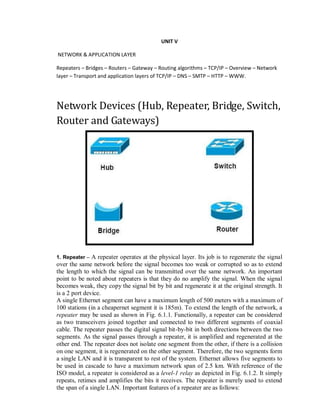
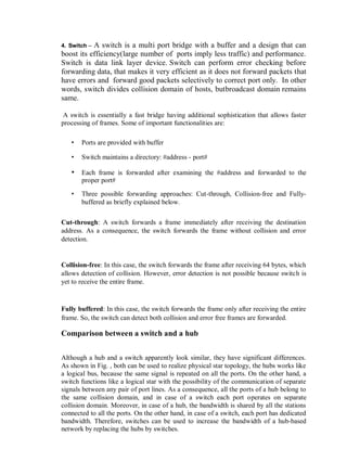
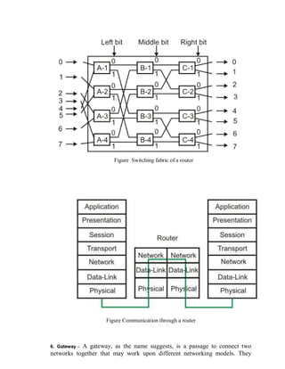
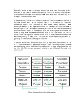
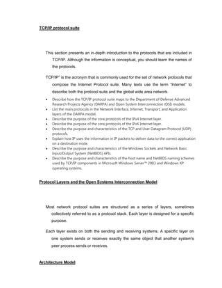
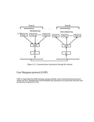
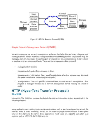
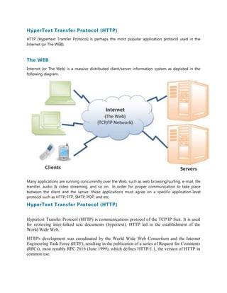
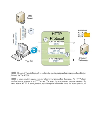
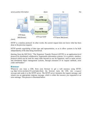
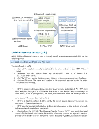
SlideShare a Scribd company logo
1 of 35
Download to read offline
UNIT V
NETWORK & APPLICATION LAYER
Repeaters – Bridges – Routers – Gateway – Routing algorithms – TCP/IP – Overview – Network
layer – Transport and application layers of TCP/IP – DNS – SMTP – HTTP – WWW.
Network Devices (Hub, Repeater, Bridge, Switch,
Router and Gateways)
1. Repeater – A repeater operates at the physical layer. Its job is to regenerate the signal
over the same network before the signal becomes too weak or corrupted so as to extend
the length to which the signal can be transmitted over the same network. An important
point to be noted about repeaters is that they do no amplify the signal. When the signal
becomes weak, they copy the signal bit by bit and regenerate it at the original strength. It
is a 2 port device.
A single Ethernet segment can have a maximum length of 500 meters with a maximum of
100 stations (in a cheapernet segment it is 185m). To extend the length of the network, a
repeater may be used as shown in Fig. 6.1.1. Functionally, a repeater can be considered
as two transceivers joined together and connected to two different segments of coaxial
cable. The repeater passes the digital signal bit-by-bit in both directions between the two
segments. As the signal passes through a repeater, it is amplified and regenerated at the
other end. The repeater does not isolate one segment from the other, if there is a collision
on one segment, it is regenerated on the other segment. Therefore, the two segments form
a single LAN and it is transparent to rest of the system. Ethernet allows five segments to
be used in cascade to have a maximum network span of 2.5 km. With reference of the
ISO model, a repeater is considered as a level-1 relay as depicted in Fig. 6.1.2. It simply
repeats, retimes and amplifies the bits it receives. The repeater is merely used to extend
the span of a single LAN. Important features of a repeater are as follows:
• A repeater connects different segments of a LAN
• A repeater forwards every frame it receives
• A repeater is a regenerator, not an amplifier
• It can be used to create a single extended LAN
Figure Repeater connecting two LAN segments
Figure Operation of a repeater as a level-1 relay
2. Hub – A hub is basically a multiport repeater. A hub connects multiple wires
coming from different branches, for example, the connector in star topology
which connects different stations. Hubs cannot filter data, so data packets are
sent to all connected devices. In other words, collision domain of all hosts
connected through Hub remains one. Also, they do not have intelligence to
find out best path for data packets which leads to inefficiencies and wastage.
Hub is a generic term, but commonly refers to a multiport repeater. It can be used to
create multiple levels of hierarchy of stations. The stations connect to the hub with RJ-45
connector having maximum segment length is 100 meters. This type of interconnected set
of stations is easy to maintain and diagnose. Figure shows how several hubs can be
connected in a hierarchical manner to realize a single LAN of bigger size with a large
number of nodes.
Figure Hub as a multi-port repeater can be connected in a hierarchical manner to form a
single LAN with many nodes
3. Bridge – A bridge operates at data link layer. A bridge is a repeater, with add
on functionality of filtering content by reading the MAC addresses of source
and destination. It is also used for interconnecting two LANs working on the
same protocol. It has a single input and single output port, thus making it a 2
port device.
The device that can be used to interconnect two separate LANs is known as a bridge. It
is commonly used to connect two similar or dissimilar LANs as shown in Fig. 6.1.4. The
bridge operates in layer 2, that is data-link layer and that is why it is called level-2 relay
with reference to the OSI model. It links similar or dissimilar LANs, designed to store
and forward frames, it is protocol independent and transparent to the end stations. The
flow of information through a bridge is shown in Fig. 6.1.5. Use of bridges offer a
number of advantages, such as higher reliability, performance, security, convenience and
larger geographic coverage. But, it is desirable that the quality of service (QOS) offered
by a bridge should match that of a single LAN. The parameters that define the QOS
include availability, frame mishaps, transit delay, frame lifetime, undetected bit errors,
frame size and priority. Key features of a bridge are mentioned below:
• A bridge operates both in physical and data-link layer
• A bridge uses a table for filtering/routing
• A bridge does not change the physical (MAC) addresses in a frame
• Types of bridges:
o Transparent Bridges o
Source routing bridges
A bridge must contain addressing and routing capability. Two routing algorithms have
been proposed for a bridged LAN environment. The first, produced as an extension of
IEEE 802.1 and applicable to all IEEE 802 LANs, is known as transparent bridge. And
the other, developed for the IEEE 802.5 token rings, is based on source routing
approach. It applies to many types of LAN including token ring, token bus and
CSMA/CD bus.
Figure A bridge connecting two separate LANs
Figure Information flow through a bridge
4. Switch – A switch is a multi port bridge with a buffer and a design that can
boost its efficiency(large number of ports imply less traffic) and performance.
Switch is data link layer device. Switch can perform error checking before
forwarding data, that makes it very efficient as it does not forward packets that
have errors and forward good packets selectively to correct port only. In other
words, switch divides collision domain of hosts, butbroadcast domain remains
same.
A switch is essentially a fast bridge having additional sophistication that allows faster
processing of frames. Some of important functionalities are:
• Ports are provided with buffer
• Switch maintains a directory: #address - port#
• Each frame is forwarded after examining the #address and forwarded to the
proper port#
• Three possible forwarding approaches: Cut-through, Collision-free and Fully-
buffered as briefly explained below.
Cut-through: A switch forwards a frame immediately after receiving the destination
address. As a consequence, the switch forwards the frame without collision and error
detection.
Collision-free: In this case, the switch forwards the frame after receiving 64 bytes, which
allows detection of collision. However, error detection is not possible because switch is
yet to receive the entire frame.
Fully buffered: In this case, the switch forwards the frame only after receiving the entire
frame. So, the switch can detect both collision and error free frames are forwarded.
Comparison between a switch and a hub
Although a hub and a switch apparently look similar, they have significant differences.
As shown in Fig. , both can be used to realize physical star topology, the hubs works like
a logical bus, because the same signal is repeated on all the ports. On the other hand, a
switch functions like a logical star with the possibility of the communication of separate
signals between any pair of port lines. As a consequence, all the ports of a hub belong to
the same collision domain, and in case of a switch each port operates on separate
collision domain. Moreover, in case of a hub, the bandwidth is shared by all the stations
connected to all the ports. On the other hand, in case of a switch, each port has dedicated
bandwidth. Therefore, switches can be used to increase the bandwidth of a hub-based
network by replacing the hubs by switches.
Figure Difference between a switch and a bridge
5. Routers – A router is a device like a switch that routes data packets based on
their IP addresses. Router is mainly a Network Layer device. Routers normally
connect LANs and WANs together and have a dynamically updating routing
table based on which they make decisions on routing the data packets. Router
divide broadcast domains of hosts connected through it.
A router is used to route data packets between two networks. It reads the information in
each packet to tell where it is going. If it is destined for an immediate network it has
access to, it will strip the outer packet (IP packet for example), readdress the packet to
the proper ethernet address, and transmit it on that network. If it is destined for another
network and must be sent to another router, it will re-package the outer packet to be
received by the next router and send it to the next router. Routing occurs at the network
layer of the OSI model. They can connect networks with different architectures such as
Token Ring and Ethernet. Although they can transform information at the data link
level, routers cannot transform information from one data format such as TCP/IP to
another such as IPX/SPX. Routers do not send broadcast packets or corrupted packets.
If the routing table does not indicate the proper address of a packet, the packet is
discarded. There are two types of routers:
1. Static routers - Are configured manually and route data packets based on
information in a router table.
2. Dynamic routers - Use dynamic routing algorithms. There are two types
of algorithms:
o Distance vector - Based on hop count, and periodically broadcasts
the routing table to other routers which takes more network
bandwidth especially with more routers. RIP uses distance
vectoring. Does not work on WANs as well as it does on LANs.
o Link state - Routing tables are broadcast at startup and then only
when they change. The open shortest path first (OSPF) protocol
uses the link state routing method to configure routes or distance
vector algorithm (DVA).
Common routing protocols include:
 IS-IS -Intermediate system to intermediate system which is a routing
protocol for the OSI suite of protocols.
 IPX - Internet Packet Exchange. Used on Netware systems.
 NLSP - Netware Link Services protocol - Uses OSPF algorithm and is
replacing IPX to provide internet capability.
 RIP - Routing information protocol uses a distance vector algorithm.
There is a device called a brouter which will function similar to a bridge for
network transport protocols that are not routable, and will function as a router
for routable protocols. It functions at the network and data link layers of the
OSI network model.
A router is considered as a layer-3 relay that operates in the network layer, that is it acts
on network layer frames. It can be used to link two dissimilar LANs. A router isolates
LANs in to subnets to manage and control network traffic. However, unlike bridges it is
not transparent to end stations. A schematic diagram of the router is shown on Fig.
6.1.13. A router has four basic components: Input ports, output ports, the routing
processor and the switching fabric. The functions of the four components are briefly
mentioned below.
• Input port performs physical and data-link layer functions of the router. As shown in
Fig. 6.1.14 (a), the ports are also provided with buffer to hold the packet before
forwarding to the switching fabric.
• Output ports, as shown in Fig., perform the same functions as the input ports, but in
the reverse order.
• The routing processor performs the function of the network layer. The process
involves table lookup.
• The switching fabric, shown in Fig. moves the packet from the input queue to the
output queue by using specialized mechanisms. The switching fabric is realized with
the help of multistage interconnection networks.
• Communication of a frame through a router is shown in Fig. 6.1.16.
Figure Schematic diagram of a router
(a)
Figure 6.1.14 Schematic diagram of a router
Figure Switching fabric of a router
Figure Communication through a router
6. Gateway – A gateway, as the name suggests, is a passage to connect two
networks together that may work upon different networking models. They
basically works as the messenger agents that take data from one system,
interpret it, and transfer it to another system. Gateways are also called protocol
converters and can operate at any network layer. Gateways are generally more
complex than switch or router.
A gateway can translate information between different network data formats or
network architectures. It can translate TCP/IP to AppleTalk so computers
supporting TCP/IP can communicate with Apple brand computers. Most
gateways operate at the application layer, but can operate at the network or
session layer of the OSI model. Gateways will start at the lower level and strip
information until it gets to the required level and repackage the information and
work its way back toward the hardware layer of the OSI model. To confuse
issues, when talking about a router that is used to interface to another network,
the word gateway is often used. This does not mean the routing machine is a
gateway as defined here, although it could be.
A gateway works above the network layer, such as application layer as shown in Fig.
6.1.17. As a consequence, it is known as a Layer-7 relay. The application level gateways
can look into the content application layer packets such as email before forwarding it to
the other side. This property has made it suitable for use in Firewalls discussed in the
next module.
Figure Communication through a gateway
TCP/IP protocol suite
This section presents an in-depth introduction to the protocols that are included in
TCP/IP. Although the information is conceptual, you should learn the names of
the protocols.

TCP/IP” is the acronym that is commonly used for the set of network protocols that
compose the Internet Protocol suite. Many texts use the term “Internet” to
describe both the protocol suite and the global wide area network.
 Describe how the TCP/IP protocol suite maps to the Department of Defense Advanced
Research Projects Agency (DARPA) and Open System Interconnection (OSI) models.
 List the main protocols in the Network Interface, Internet, Transport, and Application
layers of the DARPA model.
 Describe the purpose of the core protocols of the IPv4 Internet layer.
 Describe the purpose of the core protocols of the IPv6 Internet layer.
 Describe the purpose and characteristics of the TCP and User Datagram Protocol (UDP)
protocols.
 Explain how IP uses the information in IP packets to deliver data to the correct application
on a destination node.
 Describe the purpose and characteristics of the Windows Sockets and Network Basic
Input/Output System (NetBIOS) APIs.
 Describe the purpose and characteristics of the host name and NetBIOS naming schemes
used by TCP/IP components in Microsoft Windows Server™ 2003 and Windows XP
operating systems.
Protocol Layers and the Open Systems Interconnection Model
Most network protocol suites are structured as a series of layers, sometimes
collectively referred to as a protocol stack. Each layer is designed for a specific
purpose.

Each layer exists on both the sending and receiving systems. A specific layer on
one system sends or receives exactly the same object that another system's
peer process sends or receives.
Architecture Model
The OSI model describes idealized network communications with a family of
protocols. TCP/IP does not directly correspond to this model. TCP/IP either
combines several OSI layers into a single layer, or does not use certain layers at
all.
TCP/IP Model Layers
The TCP/IP model uses four
layers that logically span the
equivalent of the top six
layers of the OSI reference
model; this is shown (The
physical layer is not covered
by the TCP/IP model
because the data link layer is
considered the point at
which the interface occurs
between the TCP/IP stack
and the underlying
networking hardware.) The
following
are the TCP/IP model layers, starting from the bottom.
TCP/IP protocol suite maps to a four-layer conceptual model known as the DARPA model, which
was named after the U.S. government agency that initially developed TCP/IP. The four layers of
the DARPA model are: Application, Transport, Internet, and Network Interface. Each layer in the
DARPA model corresponds to one or more layers of the seven-layer OSI model.
Figure 2-1 shows the architecture of the TCP/IP protocol suite.
The TCP/IP protocol suite has two sets of protocols at the Internet layer:
 IPv4, also known as IP, is the Internet layer in common use today on private intranets and
the Internet.
 IPv6 is the new Internet layer that will eventually replace the existing IPv4 Internet layer.
Network Interface Layer
The Network Interface layer (also called the Network Access layer) sends TCP/IP packets on the
network medium and receives TCP/IP packets off the network medium. TCP/IP was designed to
be independent of the network access method, frame format, and medium. Therefore, you can
use TCP/IP to communicate across differing network types that use LAN technologies—such as
Ethernet and 802.11 wireless LAN—and WAN technologies—such as Frame Relay and
Asynchronous Transfer Mode (ATM). By being independent of any specific network technology,
TCP/IP can be adapted to new technologies.
The Network Interface layer of the DARPA model encompasses the Data Link and Physical layers
of the OSI model. The Internet layer of the DARPA model does not take advantage of sequencing
and acknowledgment services that might be present in the Data Link layer of the OSI model. The
Internet layer assumes an unreliable Network Interface layer and that reliable communications
through session establishment and the sequencing and acknowledgment of packets is the
responsibility of either the Transport layer or the Application layer.
Internet Layer
The Internet layer responsibilities include addressing, packaging, and routing functions. The
Internet layer is analogous to the Network layer of the OSI model.
The core protocols for the IPv4 Internet layer consist of the following:
 The Address Resolution Protocol (ARP) resolves the Internet layer address to a Network
Interface layer address such as a hardware address.
 The Internet Protocol (IP) is a routable protocol that addresses, routes, fragments, and
reassembles packets.
 The Internet Control Message Protocol (ICMP) reports errors and other information to
help you diagnose unsuccessful packet delivery.
 The Internet Group Management Protocol (IGMP) manages IP multicast groups.
For more information about the core protocols for the IPv4 Internet layer, see "IPv4 Internet
Layer" later in this chapter.
The core protocols for the IPv6 Internet layer consist of the following:
 IPv6 is a routable protocol that addresses and routes packets.
 The Internet Control Message Protocol for IPv6 (ICMPv6) reports errors and other
information to help you diagnose unsuccessful packet delivery.
 The Neighbor Discovery (ND) protocol manages the interactions between neighboring
IPv6 nodes.
 The Multicast Listener Discovery (MLD) protocol manages IPv6 multicast groups.
For more information about the core protocols for the IPv6 Internet layer, see "IPv6 Internet
Layer" later in this chapter.
Transport Layer
The Transport layer (also known as the Host-to-Host Transport layer) provides the Application
layer with session and datagram communication services. The Transport layer encompasses the
responsibilities of the OSI Transport layer. The core protocols of the Transport layer are TCP and
UDP.
TCP provides a one-to-one, connection-oriented, reliable communications service. TCP establishes
connections, sequences and acknowledges packets sent, and recovers packets lost during
transmission.
In contrast to TCP, UDP provides a one-to-one or one-to-many, connectionless, unreliable
communications service. UDP is used when the amount of data to be transferred is small (such as
the data that would fit into a single packet), when an application developer does not want the
overhead associated with TCP connections, or when the applications or upper-layer protocols
provide reliable delivery.
TCP and UDP operate over both IPv4 and IPv6 Internet layers.
Note The Internet Protocol (TCP/IP) component of Windows contains separate versions of the
TCP and UDP protocols than the Microsoft TCP/IP Version 6 component does. The versions in the
Microsoft TCP/IP Version 6 component are functionally equivalent to those provided with the
Microsoft Windows NT® 4.0 operating systems and contain all the most recent security updates.
The existence of separate protocol components with their own versions of TCP and UDP is known
as a dual stack architecture. The ideal architecture is known as a dual IP layer, in which the same
versions of TCP and UDP operate over both IPv4 and IPv6 (as Figure 2-1 shows). Windows Vista
has a dual IP layer architecture for the TCP/IP protocol components.
Application Layer
The Application layer allows applications to access the services of the other layers, and it defines
the protocols that applications use to exchange data. The Application layer contains many
protocols, and more are always being developed.
The most widely known Application layer protocols help users exchange information:
 The Hypertext Transfer Protocol (HTTP) transfers files that make up pages on the World
Wide Web.
 The File Transfer Protocol (FTP) transfers individual files, typically for an interactive user
session.
 The Simple Mail Transfer Protocol (SMTP) transfers mail messages and attachments.
Additionally, the following Application layer protocols help you use and manage TCP/IP networks:
 The Domain Name System (DNS) protocol resolves a host name, such as
www.microsoft.com, to an IP address and copies name information between DNS servers.
 The Routing Information Protocol (RIP) is a protocol that routers use to exchange routing
information on an IP network.
 The Simple Network Management Protocol (SNMP) collects and exchanges network
management information between a network management console and network devices
such as routers, bridges, and servers.
Windows Sockets and NetBIOS are examples of Application layer interfaces for TCP/IP
applications. For more information, see “Application Programming Interfaces” later in this chapter.
Top of page
Physical network layer
The physical network layer specifies the characteristics of the hardware to be used
for the network.

For example, physical network layer specifies the physical
characteristics of the communications media.

The physical layer of TCP/IP describes hardware standards such as IEEE 802.3,
the specification for Ethernet network media, and RS-232, the specification for
standard pin connectors.
Data-Link Layer
The data-link layer identifies the network protocol type of the packet, in this instance
TCP/IP.

The data-link layer also provides error control and “framing.”

Examples of data-link layer protocols are Ethernet IEEE 802.2 framing and Point-to-
Point Protocol (PPP) framing.
Network Layer
The Internet layer, also known as the network layer or IP layer, accepts and delivers
packets for the network.

This layer includes the powerful Internet Protocol (IP), the Address Resolution
Protocol (ARP), and the Internet Control Message Protocol (ICMP).
IP Protocol
 The IP protocol and its associated routing protocols are possibly the most
significant of the entire TCP/IP suite. IP is responsible for the following:
IP addressing
The IP addressing conventions are part of the IP protocol. Designing an IPv4
Addressing Scheme introduces IPv4 addressing and IPv6 Addressing Overview
introduces IPv6 addressing.
Host-to-host communications – IP determines the path a packet must take, based on
the
receiving system's IP address.
ARP Protocol
The Address Resolution Protocol (ARP) conceptually exists between the data-
link and Internet layers.
hapter11 Iteroperability
 ARP assists IP in directing datagram’s to the appropriate receiving system
by mapping Ethernet addresses (48 bits long) to known IP addresses (32
bits long).
ICMP Protocol
The Internet Control Message Protocol (ICMP) detects and reports network
error conditions. ICMP reports on the following:

Dropped packets – Packets that arrive too fast to be processed

Connectivity failure – A destination system cannot be reached
Transport Layer
The TCP/IP transport layer ensures that packets arrive in sequence and without
error, by swapping acknowledgments of data reception, and retransmitting lost
packets.

This type of communication is known as end-to-end. Transport layer protocols at
this level are Transmission Control Protocol (TCP), User Datagram Protocol
(UDP), and Stream Control Transmission Protocol (SCTP). TCP and SCTP
provide reliable, end-to-end service.

UDP provides unreliable datagram service.
TCP Protocol
TCP enables applications to communicate with each other as though they were
connected by a physical circuit.

TCP sends data in a form that appears to be transmitted in a character-by-character
fashion, rather than as discrete packets. This transmission consists of the
following:
SCTP Protocol
SCTP is a reliable, connection-oriented transport layer protocol that provides the
same services to applications that are available from TCP.

Moreover, SCTP can support connections between systems that have more than
one address, or multihued.

The SCTP connection between sending and receiving system is called an
association.
Application Layer
The application layer defines standard Internet services and network applications
that anyone can use.

These services work with the transport layer to send and receive data. Many
application layer protocols exist.

The following list shows examples of application layer protocols:
1.Standard TCP/IP services such as the ftp, tftp, and telnet
commands


• Node-to-node delivery: At the data-link level, delivery of frames take place
between two nodes connected by a point-to-point link or a LAN, by using the
data-link layers address, say MAC address.
• Host-to-host delivery: At the network level, delivery of datagrams can take place
between two hosts by using IP address.
From user’s point of view, the TCP/IP-based internet can be considered as a set of
application programs that use the internet to carry out useful communication tasks. Most
popular internet applications include Electronic mail, File transfer, and Remote login. IP
allows transfer of IP datagrams among a number of stations or hosts, where the datagram
is routed through the internet based on the IP address of the destination. But, in this case,
several application programs (processes) simultaneously running on a source host has to
communicate with the corresponding processes running on a remote destination host
through the internet. This requires an additional mechanism called process-to-process
delivery, which is implemented with the help of a transport -level protocol. The transport
level protocol will require an additional address, known as port number, to select a
particular process among multiple processes running on the destination host. So, there is
a requirement of the following third type of delivery system.
• Process-to-process delivery: At the transport level, communication can take
place between processes or application programs by using port addresses
Basic communication mechanism is shown in Fig. 6.3.1. The additional mechanism
needed to facilitate multiple application programs in different stations to communicate
with each other simultaneously can be provided by a transport level protocol such as
UDP or TCP, which are discussed in this lesson.
. 6.3.2.
Figure 6.3.1 Communication mechanism through the internet
User Datagram protocol (UDP)
UDP is responsible for differentiating among multiple source and destination processes
within one host. Multiplexing and demultiplexing operations are performed using the port
mechanism as depicted in Fig
Figure 6.3.2 Multiplexing and demultiplexing mechanism of UDP
UDP Datagram
The UDP datagram format is shown in Fig. 6.3.3. A brief description of different fields of
the datagram are given below:
• Source port (16 bits): It defines the port number of the application program in the host
of the sender
• Destination port (16 bits): It defines the port number of the application program in the
host of the receiver
• Length: It provides a count of octets in the UDP datagram, minimum length = 8
• Checksum: It is optional, 0 in case it is not in use
Characteristics of the UDP
Key characteristics of UDP are given below:
• UDP provides an unreliable connectionless delivery service using IP to
transport messages between two processes
• UDP messages can be lost, duplicated, delayed and can be delivered out of order
• UDP is a thin protocol, which does not add significantly to the functionality of IP
• It cannot provide reliable stream transport service
The above limitations can be overcome by using connection-oriented transport layer
protocol known as Transmission Control Protocol (TCP), which is presented in the
following section.
Transmission Control Protocol (TCP)
TCP provides a connection-oriented, full -duplex, reliable, streamed delivery service
using IP to transport messages between two processes.
Reliability is ensured by:
• Connection-oriented service
• Flow control using sliding window protocol
• Error detection using checksum
• Error control using go-back-N ARQ technique
• Congestion avoidance algorithms; multiplicative decrease and slow-start
TCP Datagram
The TCP datagram format is shown in Fig. 6.3.4. A brief explanation of the functions of
different fields are given below:
• Source port (16 bits): It defines the port number of the application program in the host
of the sender
• Destination port (16 bits): It defines the port number of the application program in the
host of the receiver
• Sequence number (32 bits): It conveys the receiving host which octet in this sequence
comprises the first byte in the segment
• Acknowledgement number (32 bits): This specifies the sequence number of the next
octet that receiver expects to receive
• HLEN (4 bits): This field specifies the number of 32-bit words present in the TCP
header
• Control flag bits (6 bits): URG: Urgent pointer
• ACK: Indicates whether acknowledge field is valid
• PSH: Push the data without buffering
• RST: Resent the connection
• SYN: Synchronize sequence numbers during connection establishment
• FIN: Terminate the connection
• Window (16 bits): Specifies the size of window
• Checksum (16 bits): Checksum used for error detection.
• User pointer (16 bits): Used only when URG flag is valid
• Options: Optional 40 bytes of information
The well-known ports used by TCP are given in Table 6.3.2 and the three types of
addresses used in TCP/IP are shown in Fig. 6.3.5. TCP establishes a virtual path between
the source and destination processes before any data communication by using two
procedures, connection establishment to start reliably and connection termination to
terminate gracefully, as discussed in the following subsection.
Figure 6.3.4 The TCP datagram format
Figure 6.3.5 Three types of addresses used in TCP/IP
Table 6.3.2 Well-known ports used by TCP
Electronic Mail
Simple Mail Transfer Protocol (SMTP) is an Internet standard for electronic mail (e-
mail) transmission across Internet Protocol (IP) networks.
SMTP is a connection-oriented, text-based protocol in which a mail sender communicates
with a mail receiver by issuing command strings and supplying necessary data over a
reliable ordered data stream channel, typically a Transmission Control Protocol (TCP)
connection. An SMTP session consists of commands originated by an SMTP client (the
initiating agent, sender, or transmitter) and corresponding responses from the SMTP
server (the listening agent, or receiver) so that the session is opened, and session
parameters are exchanged. A session may include zero or more SMTP transactions. An
SMTP transaction consists of three command/reply sequences (see example below.) They
are:
1. MAIL command, to establish the return address, a.k.a. Return-Path, 5321.From,
mfrom, or
envelope sender. This is the address for bounce messages.
2. RCPT command, to establish a recipient of this message. This command can be issued
multiple
times, one for each recipient. These addresses are also part of the envelope.
3. DATA to send the message text. This is the content of the message, as opposed to its
envelope.
It consists of a message header and a message body separated by an empty line. DATA is
actually a group of commands, and the server replies twice: once to the DATA command
proper, to acknowledge that it is ready to receive the text, and the second time after the
end-of-data sequence, to either accept or reject the entire message.
Electronic mail is among the most widely available application services. Each user, who
intends to participate in email communication, is assigned a mailbox, where out-going
and incoming messages are buffered, allowing the transfer to take place in
thebackground. The message contains a header that specifies the sender, recipients, and
subject, followed by a body that contains message. The TCP/IP protocol that supports
electronic mail on the internet is called Simple Mail Transfer Protocol (SMTP), which
supports the following:
• Sending a message to one or more recipients
• Sending messages that include text, voice, video, or graphics
A software package, known as User Agent, is used to compose, read, reply or forward
emails and handle mailboxes. The email address consists of two parts divided by a @
character. The first part is the local name that identifies mailbox and the second part is a
domain name.
Figure 6.3.14 Simple Mail Transfer Protocol (SMTP)
Telnet
Telnet is a simple remote terminal protocol that provides a remote log-on capability,
which enables a user to log on to a remote computer and behaves as if it is directly
connected to it. The following three basic services are offered by TELNET:
• It defines a network virtual terminal that provides a standard interface to
remote systems
o It includes a mechanism that allows the client and server to negotiate options
from a standard set
o It treats both ends symmetrically
File Transfer Protocol (FTP)
File Transfer Protocol (FTP) is a TCP/IP client -server application for transfer files
between two remote machines through internet. A TCP connection is set up before file
transfer and it persists throughout the session. It is possible to send more than one file
before disconnecting the link. A control connection is established first with a remote host
before any file can be transferred. Two connections required are shown in Fig. 6.3.15.
Users view FTP as an interactive system
Figure 6.3.15 File Transfer Protocol (FTP)
Simple Network Management Protocol (SNMP)
Network managers use network management software that help them to locate, diagnose and
rectify problems. Simple Network Management Protocol (SMTP) provides a systematic way for
managing network resources. It uses transport layer protocol for communication. It allows them
to monitor switches, routers and hosts. There are four components of the protocol:
• Management of systems
• Management of nodes; hosts, routers, switches
• Management of Information Base; specifies data items a host or a router must keep and
the operations allowed on each (eight categories)
• Management of Protocol; specifies communication between network management client
program a manager invokes and a network management server running on a host or
router
HTTP (HyperText Transfer Protocol)
The WEB
Internet (or The Web) is a massive distributed client/server information system as depicted in the
following diagram.
Many applications are running concurrently over the Web, such as web browsing/surfing, e-mail, file
transfer, audio & video streaming, and so on. In order for proper communication to take place
between the client and the server, these applications must agree on a specific application-level
protocol such as HTTP, FTP, SMTP, POP, and etc.
HyperText Transfer Protocol (HTTP)
HTTP (Hypertext Transfer Protocol) is perhaps the most popular application protocol used in the
Internet (or The WEB).
The WEB
Internet (or The Web) is a massive distributed client/server information system as depicted in the
following diagram.
Many applications are running concurrently over the Web, such as web browsing/surfing, e-mail, file
transfer, audio & video streaming, and so on. In order for proper communication to take place
between the client and the server, these applications must agree on a specific application-level
protocol such as HTTP, FTP, SMTP, POP, and etc.
HyperText Transfer Protocol (HTTP)
Hypertext Transfer Protocol (HTTP) is communications protocol of the TCP/IP Suit. It is used
for retrieving inter-linked text documents (hypertext). HTTP led to the establishment of the
World Wide Web.
HTTP's development was coordinated by the World Wide Web Consortium and the Internet
Engineering Task Force (IETF), resulting in the publication of a series of Request for Comments
(RFCs), most notably RFC 2616 (June 1999), which defines HTTP/1.1, the version of HTTP in
common use.
HTTP is a request/response standard between a client and a server. The end-user client making a
HTTP request—using a web browser typically—is referred to as the user agent. The responding
server—which serves resources such as HTML files and images—is called the origin server.
Typically, an HTTP client initiates a request. It establishes a Transmission Control Protocol
(TCP) connection to a particular port on a host (port 80 by default). An HTTP server listening on
that port waits for the client to send a request message. Upon receiving the request, the server
sends back the requested resource. Resources to be accessed by HTTP are identified using
Uniform Resource Identifiers (URIs) (or, more specifically, Uniform Resource Locators (URLs))
using the http: or https: URI schemes.
Here is how HTTP works:
1. You type a website's URL, for example, www.ustudy.in in your favorite browser (IE, Firefox, Opera,
Safari)
2. Your web browser looks up the IP address of www.ustudy.in using DNS services - it is
resolved as 202.54.158.131.
3. Your web browser then establishes a TCP connection to the IP address 202.54.158.131 on port
80. The web browser's packets are transported to the Ustudy.in server over the internet using IP.
The server for UStudy.in successfully receives the packet and acknowledges a connection. On
seeing it is for port 80, delivers it to the web server software (apache, IIS etc.).
HTTP (Hypertext Transfer Protocol) is perhaps the most popular application protocol used in the
Internet (or The WEB).
HTTP is an asymmetric request-response client-server protocol as illustrated. An HTTP client
sends a request message to an HTTP server. The server, in turn, returns a response message. In
other words, HTTP is apull protocol, the client pulls information from the server (instead of
server pushes information down to the
client).
HTTP is a stateless protocol. In other words, the current request does not know what has been
done in the previous requests.
HTTP permits negotiating of data type and representation, so as to allow systems to be built
independently of the data being transferred.
Quoting from the RFC2616: "The Hypertext Transfer Protocol (HTTP) is an application-level
protocol for distributed, collaborative, hypermedia information systems. It is a generic, stateless,
protocol which can be used for many tasks beyond its use for hypertext, such as name servers
and distributed object management systems, through extension of its request methods, error
codes and headers."
Browser
Whenever you issue a URL from your browser to get a web resource using HTTP,
e.g. http://www.nowhere123.com/index.html, the browser turns the URL into a request
message and sends it to the HTTP server. The HTTP server interprets the request message, and
returns you an appropriate response message, which is either the resource you requested or an
error message. This process is illustrated below:
Uniform Resource Locator (URL)
A URL (Uniform Resource Locator) is used to uniquely identify a resource over the web. URL has the
following syntax:
protocol://hostname:port/path-and-file-name
There are 4 parts in a URL:
1. Protocol: The application-level protocol used by the client and server, e.g., HTTP, FTP, and
telnet.
2. Hostname: The DNS domain name (e.g., www.nowhere123.com) or IP address (e.g.,
192.128.1.2) of the server.
3. Port: The TCP port number that the server is listening for incoming requests from the clients.
4. Path-and-file-name: The name and location of the requested resource, under the server
document base directory.
 HTTP is an asymmetric request-response client-server protocol as illustrated. An HTTP client
sends a request message to an HTTP server. The server, in turn, returns a response message. In
other words, HTTP is apull protocol, the client pulls information from the server (instead of
server pushes information down to the client).
 HTTP is a stateless protocol. In other words, the current request does not know what has
been done in the previous requests.
 HTTP permits negotiating of data type and representation, so as to allow systems to be built
independently of the data being transferred.
 Quoting from the RFC2616: "The Hypertext Transfer Protocol (HTTP) is an application-level
protocol for distributed, collaborative, hypermedia information systems. It is a generic, stateless,
protocol which can be used for many tasks beyond its use for hypertext, such as name servers
and distributed object management systems, through extension of its request methods, error
codes and headers."
World Wide Web (WWW)
 The World Wide Web (WWW) is a repository of information linked together from points all
over the world. The WWW has a unique combination of flexibility, portability, and user-friendly
features that distinguish it from other services provided by the Internet.
 Each site holds one or more documents, referred to as Web pages. Each Web page can contain
a link to other pages in the same site or at other sites. The pages can be retrieved and viewed by
using browsers.
Client (Browser)
A variety of vendors offer commercial browsers that interpret and display a Web document, and
all use nearly the same architecture. Each browser usually consists of three parts: a controller,
client protocol, and interpreters. The controller receives input from the keyboard or the mouse
and uses the client programs to access the document. After the document has been accessed,
the controller uses one of the interpreters to display the document on the screen. The client
protocol can be one of the protocols described previously such as FTP or HTTP (described later
in the chapter). The interpreter can be HTML, Java, or JavaScript, depending on the type of
document.
Server
The Web page is stored at the server. Each time a client request arrives, the corresponding document is
sent to the client. To improve efficiency, servers normally store requested files in a cache in memory;
memory is faster to access than disk. A server can also become more efficient through multithreading or
multiprocessing. In this case, a server can answer more than one request at a time.
Review Questions
Q1. What is the relationship between TCP/IP and Internet?
Ans: Internet is a network of different types of network. TCP/IP is a set of rules and procedures
that govern the exchange of messages between hosts linked to different networks. TCP/IP creates
an environment as if all hosts are connected to a single logical network.
Q2. Distinguish between TCP and UDP?
Ans: Both TCP and UDP belong to transport layer. The UDP is simpler with much less
overhead. UDP provides unreliable connectionless service. On the other hand, TCP provides
connection oriented reliable service with the help of suitable flow control and error control
protocols. As a consequence, TCP has much more overhead.
Q3. What is the main function of UDP protocol?
Ans: UDP protocol provides user programs the ability to communicate using unreliable
connectionless packet delivery service with minimum overhead.
Q4. Why pseudo-header is added in a UDP datagram?
Ans: As the UDP datagram does not contain source and destination address information, a
pseudo-header is added with these information to verify that the UDP datagram has reached its
correct destination.
Q5. What protocol is used by TCP for flow control?
Ans. TCP uses sliding window protocol for flow control.
Q6. What ARQ protocol is used in TCP?
Ans. Go-back-N ARQ.
Q7. What is piggybacking?
Ans. Instead of sending a separate packet for positive/negative acknowledgement, piggybacking
technique utilizes the full-duplex communication environment of TCP. The positive/negative
acknowledgement information is added to a normal packet sent by the receiving side. It helps to
save precious network bandwidth.
Q8. How TCP establishes and terminates connection?
Ans. TCP establishes connection using a three-way handshaking protocol and connection is
terminated by a 2-way/4-way handshaking protocol.
Q9. What are the advantages of DNS?
Ans: Key advantage of DNS is the use of a hierarchical naming system and the use of distributed
database to store the huge amount of address information in many servers. The host that needs
mapping of name to address can contact the closest server holding the required information.
Q10. What kind of paradigm is used by the application layer protocols? Ans.
Client-Server paradigm is used by all the application layer protocols.
Q1.Why do you need internetworking?
Ans: As stations connected to different LANs and WANs want to communicate with each other,
it is necessary to provide this facility. Internetworking creates a single virtual network over
which all stations in different network can communicate seamlessly and transparently.
Q2. Why a repeater is called level-1 relay?
Ans: A repeater operates in the physical layer. Data received on one of its ports is relayed on the
remaining port bit-by-bit without looking into the contents. That is why repeater is called a level-
1 relay.
Q3. What is bridge? How it operates in the internetworking scenario?
Ans: A bridge operates in the Data link layer. It looks into various fields of a frame to take
various actions. For example, it looks at the destination address field so that it can forward the
frame to a port where destination stations is connected. It also looks at the FCS field to check
error in the received frame, it any. A bridge helps to create a network having different collision
domains.
Q4. Why spanning tree topology is necessary for routing using a bridge?
Ans: If there exit more than one path between two LANs through different bridges, there is a
possibility of continuous looping of a frame between the LANs. To avoid the loop problem,
spanning tree topology is used. It is essentially an overlay of tree topology on the physical graph
topology, providing only one path between any two LANs.
Q5. What is discovery frame?
Ans: In the source routing protocol, a host can discover a route by sending a discovery frame,
which spreads through the entire network using all possible paths to the destination. Each frame
gradually gathers addresses as it goes. The destination responds to each frame and the source
host chooses an appropriate route from these responses.
Q6. What limitation of transparent bridge protocol is overcome by the source routing protocol?
Ans: Transparent bridge protocol uses spanning tree algorithm, where a unique path is used for
communication between two stations. As a consequence, it does not make use of other paths
leading to lesser utilization of network resources. This problem is overcome in source routing
algorithm.
Q7. What limitations of a bridge are overcome by a router? Ans: A
router overcomes the following limitations of a bridge:
o Linking of two dissimilar networks
• Routing data selectively and efficiently
• Enforcement of security
• Vulnerability to broadcast storm

More Related Content

Similar to equipment list.pdf

connecting LANs.pptx
connecting LANs.pptxconnecting LANs.pptx
connecting LANs.pptxJayaprasanna4
 
Networking devices
Networking devicesNetworking devices
Networking devicesrupinderj
 
Network connecting devices and their security
Network connecting devices and their securityNetwork connecting devices and their security
Network connecting devices and their securitylovizabasharat
 
Networking Devices & Its Advantages and Disadvantages
Networking Devices & Its Advantages and DisadvantagesNetworking Devices & Its Advantages and Disadvantages
Networking Devices & Its Advantages and DisadvantagesAnit Thapaliya
 
SYBSC IT COMPUTER NETWORKS UNIT III Connecting LANs, Backbone Networks, and V...
SYBSC IT COMPUTER NETWORKS UNIT III Connecting LANs, Backbone Networks, and V...SYBSC IT COMPUTER NETWORKS UNIT III Connecting LANs, Backbone Networks, and V...
SYBSC IT COMPUTER NETWORKS UNIT III Connecting LANs, Backbone Networks, and V...Arti Parab Academics
 
Networkingdevices 120505003202-phpapp02
Networkingdevices 120505003202-phpapp02Networkingdevices 120505003202-phpapp02
Networkingdevices 120505003202-phpapp02Aman Jaiswal
 
Deployment guide1
Deployment guide1Deployment guide1
Deployment guide1Programmer
 
Chapter V-Connecting LANs, Backbone Networks, and Virtual LANs.pptx
Chapter V-Connecting LANs, Backbone Networks, and Virtual LANs.pptxChapter V-Connecting LANs, Backbone Networks, and Virtual LANs.pptx
Chapter V-Connecting LANs, Backbone Networks, and Virtual LANs.pptxWillianApaza
 
19 24 cn practicals
19 24 cn practicals19 24 cn practicals
19 24 cn practicalsMakavanaVeer
 
Computer Network Components
Computer Network  ComponentsComputer Network  Components
Computer Network ComponentsJyoti Akhter
 
Network Management Devices
Network Management DevicesNetwork Management Devices
Network Management DevicesRahul P
 
Network Topologies, L1-L2 Basics, Networking Devices
Network Topologies, L1-L2 Basics, Networking DevicesNetwork Topologies, L1-L2 Basics, Networking Devices
Network Topologies, L1-L2 Basics, Networking DevicesAalok Shah
 
chaptet 4 DC and CN.ppt
chaptet 4 DC and CN.pptchaptet 4 DC and CN.ppt
chaptet 4 DC and CN.pptEliasPetros
 

Similar to equipment list.pdf (20)

connecting LANs.pptx
connecting LANs.pptxconnecting LANs.pptx
connecting LANs.pptx
 
Networking devices
Networking devicesNetworking devices
Networking devices
 
Network connecting devices and their security
Network connecting devices and their securityNetwork connecting devices and their security
Network connecting devices and their security
 
Networking Devices & Its Advantages and Disadvantages
Networking Devices & Its Advantages and DisadvantagesNetworking Devices & Its Advantages and Disadvantages
Networking Devices & Its Advantages and Disadvantages
 
SYBSC IT COMPUTER NETWORKS UNIT III Connecting LANs, Backbone Networks, and V...
SYBSC IT COMPUTER NETWORKS UNIT III Connecting LANs, Backbone Networks, and V...SYBSC IT COMPUTER NETWORKS UNIT III Connecting LANs, Backbone Networks, and V...
SYBSC IT COMPUTER NETWORKS UNIT III Connecting LANs, Backbone Networks, and V...
 
Networkingdevices 120505003202-phpapp02
Networkingdevices 120505003202-phpapp02Networkingdevices 120505003202-phpapp02
Networkingdevices 120505003202-phpapp02
 
Deployment guide1
Deployment guide1Deployment guide1
Deployment guide1
 
CCNA DUMPS 640-802
CCNA DUMPS 640-802CCNA DUMPS 640-802
CCNA DUMPS 640-802
 
Chapter V-Connecting LANs, Backbone Networks, and Virtual LANs.pptx
Chapter V-Connecting LANs, Backbone Networks, and Virtual LANs.pptxChapter V-Connecting LANs, Backbone Networks, and Virtual LANs.pptx
Chapter V-Connecting LANs, Backbone Networks, and Virtual LANs.pptx
 
19 24 cn practicals
19 24 cn practicals19 24 cn practicals
19 24 cn practicals
 
Network hardware.ppt
Network hardware.pptNetwork hardware.ppt
Network hardware.ppt
 
Computer Network Components
Computer Network  ComponentsComputer Network  Components
Computer Network Components
 
Network hardware essentials Lec#3
Network hardware essentials Lec#3Network hardware essentials Lec#3
Network hardware essentials Lec#3
 
Network Management Devices
Network Management DevicesNetwork Management Devices
Network Management Devices
 
Computer networking
Computer networkingComputer networking
Computer networking
 
Cna
CnaCna
Cna
 
PPT Backbone And Networks
PPT Backbone And NetworksPPT Backbone And Networks
PPT Backbone And Networks
 
Network Topologies, L1-L2 Basics, Networking Devices
Network Topologies, L1-L2 Basics, Networking DevicesNetwork Topologies, L1-L2 Basics, Networking Devices
Network Topologies, L1-L2 Basics, Networking Devices
 
chaptet 4 DC and CN.ppt
chaptet 4 DC and CN.pptchaptet 4 DC and CN.ppt
chaptet 4 DC and CN.ppt
 
Network devices
Network devicesNetwork devices
Network devices
 

Recently uploaded

如何办理(UCLA毕业证书)加州大学洛杉矶分校毕业证成绩单留信学历认证原版一比一
如何办理(UCLA毕业证书)加州大学洛杉矶分校毕业证成绩单留信学历认证原版一比一如何办理(UCLA毕业证书)加州大学洛杉矶分校毕业证成绩单留信学历认证原版一比一
如何办理(UCLA毕业证书)加州大学洛杉矶分校毕业证成绩单留信学历认证原版一比一ga6c6bdl
 
Call Girls in Nagpur Bhavna Call 7001035870 Meet With Nagpur Escorts
Call Girls in Nagpur Bhavna Call 7001035870 Meet With Nagpur EscortsCall Girls in Nagpur Bhavna Call 7001035870 Meet With Nagpur Escorts
Call Girls in Nagpur Bhavna Call 7001035870 Meet With Nagpur Escortsranjana rawat
 
Vip Noida Escorts 9873940964 Greater Noida Escorts Service
Vip Noida Escorts 9873940964 Greater Noida Escorts ServiceVip Noida Escorts 9873940964 Greater Noida Escorts Service
Vip Noida Escorts 9873940964 Greater Noida Escorts Serviceankitnayak356677
 
《伯明翰城市大学毕业证成绩单购买》学历证书学位证书区别《复刻原版1:1伯明翰城市大学毕业证书|修改BCU成绩单PDF版》Q微信741003700《BCU学...
《伯明翰城市大学毕业证成绩单购买》学历证书学位证书区别《复刻原版1:1伯明翰城市大学毕业证书|修改BCU成绩单PDF版》Q微信741003700《BCU学...《伯明翰城市大学毕业证成绩单购买》学历证书学位证书区别《复刻原版1:1伯明翰城市大学毕业证书|修改BCU成绩单PDF版》Q微信741003700《BCU学...
《伯明翰城市大学毕业证成绩单购买》学历证书学位证书区别《复刻原版1:1伯明翰城市大学毕业证书|修改BCU成绩单PDF版》Q微信741003700《BCU学...ur8mqw8e
 
(办理学位证)加州州立大学北岭分校毕业证成绩单原版一比一
(办理学位证)加州州立大学北岭分校毕业证成绩单原版一比一(办理学位证)加州州立大学北岭分校毕业证成绩单原版一比一
(办理学位证)加州州立大学北岭分校毕业证成绩单原版一比一Fi sss
 
如何办理(Adelaide毕业证)阿德莱德大学毕业证成绩单Adelaide学历认证真实可查
如何办理(Adelaide毕业证)阿德莱德大学毕业证成绩单Adelaide学历认证真实可查如何办理(Adelaide毕业证)阿德莱德大学毕业证成绩单Adelaide学历认证真实可查
如何办理(Adelaide毕业证)阿德莱德大学毕业证成绩单Adelaide学历认证真实可查awo24iot
 
Gaya Call Girls #9907093804 Contact Number Escorts Service Gaya
Gaya Call Girls #9907093804 Contact Number Escorts Service GayaGaya Call Girls #9907093804 Contact Number Escorts Service Gaya
Gaya Call Girls #9907093804 Contact Number Escorts Service Gayasrsj9000
 
如何办理萨省大学毕业证(UofS毕业证)成绩单留信学历认证原版一比一
如何办理萨省大学毕业证(UofS毕业证)成绩单留信学历认证原版一比一如何办理萨省大学毕业证(UofS毕业证)成绩单留信学历认证原版一比一
如何办理萨省大学毕业证(UofS毕业证)成绩单留信学历认证原版一比一ga6c6bdl
 
(ZARA) Call Girls Jejuri ( 7001035870 ) HI-Fi Pune Escorts Service
(ZARA) Call Girls Jejuri ( 7001035870 ) HI-Fi Pune Escorts Service(ZARA) Call Girls Jejuri ( 7001035870 ) HI-Fi Pune Escorts Service
(ZARA) Call Girls Jejuri ( 7001035870 ) HI-Fi Pune Escorts Serviceranjana rawat
 
(SANA) Call Girls Landewadi ( 7001035870 ) HI-Fi Pune Escorts Service
(SANA) Call Girls Landewadi ( 7001035870 ) HI-Fi Pune Escorts Service(SANA) Call Girls Landewadi ( 7001035870 ) HI-Fi Pune Escorts Service
(SANA) Call Girls Landewadi ( 7001035870 ) HI-Fi Pune Escorts Serviceranjana rawat
 
如何办理伦敦大学伯贝克学院毕业证(BBK毕业证) 成绩单留信学历认证原版一比一
如何办理伦敦大学伯贝克学院毕业证(BBK毕业证) 成绩单留信学历认证原版一比一如何办理伦敦大学伯贝克学院毕业证(BBK毕业证) 成绩单留信学历认证原版一比一
如何办理伦敦大学伯贝克学院毕业证(BBK毕业证) 成绩单留信学历认证原版一比一ga6c6bdl
 
Papular No 1 Online Istikhara Amil Baba Pakistan Amil Baba In Karachi Amil B...
Papular No 1 Online Istikhara Amil Baba Pakistan  Amil Baba In Karachi Amil B...Papular No 1 Online Istikhara Amil Baba Pakistan  Amil Baba In Karachi Amil B...
Papular No 1 Online Istikhara Amil Baba Pakistan Amil Baba In Karachi Amil B...Authentic No 1 Amil Baba In Pakistan
 
定制(Salford学位证)索尔福德大学毕业证成绩单原版一比一
定制(Salford学位证)索尔福德大学毕业证成绩单原版一比一定制(Salford学位证)索尔福德大学毕业证成绩单原版一比一
定制(Salford学位证)索尔福德大学毕业证成绩单原版一比一ss ss
 
Pallawi 9167673311 Call Girls in Thane , Independent Escort Service Thane
Pallawi 9167673311  Call Girls in Thane , Independent Escort Service ThanePallawi 9167673311  Call Girls in Thane , Independent Escort Service Thane
Pallawi 9167673311 Call Girls in Thane , Independent Escort Service ThanePooja Nehwal
 
Hifi Defence Colony Call Girls Service WhatsApp -> 9999965857 Available 24x7 ...
Hifi Defence Colony Call Girls Service WhatsApp -> 9999965857 Available 24x7 ...Hifi Defence Colony Call Girls Service WhatsApp -> 9999965857 Available 24x7 ...
Hifi Defence Colony Call Girls Service WhatsApp -> 9999965857 Available 24x7 ...srsj9000
 
Call Girls in Dwarka Sub City 💯Call Us 🔝8264348440🔝
Call Girls in Dwarka Sub City 💯Call Us 🔝8264348440🔝Call Girls in Dwarka Sub City 💯Call Us 🔝8264348440🔝
Call Girls in Dwarka Sub City 💯Call Us 🔝8264348440🔝soniya singh
 
(办理学位证)韩国汉阳大学毕业证成绩单原版一比一
(办理学位证)韩国汉阳大学毕业证成绩单原版一比一(办理学位证)韩国汉阳大学毕业证成绩单原版一比一
(办理学位证)韩国汉阳大学毕业证成绩单原版一比一C SSS
 
Slim Call Girls Service Badshah Nagar * 9548273370 Naughty Call Girls Service...
Slim Call Girls Service Badshah Nagar * 9548273370 Naughty Call Girls Service...Slim Call Girls Service Badshah Nagar * 9548273370 Naughty Call Girls Service...
Slim Call Girls Service Badshah Nagar * 9548273370 Naughty Call Girls Service...nagunakhan
 
(办理学位证)多伦多大学毕业证成绩单原版一比一
(办理学位证)多伦多大学毕业证成绩单原版一比一(办理学位证)多伦多大学毕业证成绩单原版一比一
(办理学位证)多伦多大学毕业证成绩单原版一比一C SSS
 

Recently uploaded (20)

如何办理(UCLA毕业证书)加州大学洛杉矶分校毕业证成绩单留信学历认证原版一比一
如何办理(UCLA毕业证书)加州大学洛杉矶分校毕业证成绩单留信学历认证原版一比一如何办理(UCLA毕业证书)加州大学洛杉矶分校毕业证成绩单留信学历认证原版一比一
如何办理(UCLA毕业证书)加州大学洛杉矶分校毕业证成绩单留信学历认证原版一比一
 
Call Girls in Nagpur Bhavna Call 7001035870 Meet With Nagpur Escorts
Call Girls in Nagpur Bhavna Call 7001035870 Meet With Nagpur EscortsCall Girls in Nagpur Bhavna Call 7001035870 Meet With Nagpur Escorts
Call Girls in Nagpur Bhavna Call 7001035870 Meet With Nagpur Escorts
 
Vip Noida Escorts 9873940964 Greater Noida Escorts Service
Vip Noida Escorts 9873940964 Greater Noida Escorts ServiceVip Noida Escorts 9873940964 Greater Noida Escorts Service
Vip Noida Escorts 9873940964 Greater Noida Escorts Service
 
《伯明翰城市大学毕业证成绩单购买》学历证书学位证书区别《复刻原版1:1伯明翰城市大学毕业证书|修改BCU成绩单PDF版》Q微信741003700《BCU学...
《伯明翰城市大学毕业证成绩单购买》学历证书学位证书区别《复刻原版1:1伯明翰城市大学毕业证书|修改BCU成绩单PDF版》Q微信741003700《BCU学...《伯明翰城市大学毕业证成绩单购买》学历证书学位证书区别《复刻原版1:1伯明翰城市大学毕业证书|修改BCU成绩单PDF版》Q微信741003700《BCU学...
《伯明翰城市大学毕业证成绩单购买》学历证书学位证书区别《复刻原版1:1伯明翰城市大学毕业证书|修改BCU成绩单PDF版》Q微信741003700《BCU学...
 
(办理学位证)加州州立大学北岭分校毕业证成绩单原版一比一
(办理学位证)加州州立大学北岭分校毕业证成绩单原版一比一(办理学位证)加州州立大学北岭分校毕业证成绩单原版一比一
(办理学位证)加州州立大学北岭分校毕业证成绩单原版一比一
 
9953330565 Low Rate Call Girls In Jahangirpuri Delhi NCR
9953330565 Low Rate Call Girls In Jahangirpuri  Delhi NCR9953330565 Low Rate Call Girls In Jahangirpuri  Delhi NCR
9953330565 Low Rate Call Girls In Jahangirpuri Delhi NCR
 
如何办理(Adelaide毕业证)阿德莱德大学毕业证成绩单Adelaide学历认证真实可查
如何办理(Adelaide毕业证)阿德莱德大学毕业证成绩单Adelaide学历认证真实可查如何办理(Adelaide毕业证)阿德莱德大学毕业证成绩单Adelaide学历认证真实可查
如何办理(Adelaide毕业证)阿德莱德大学毕业证成绩单Adelaide学历认证真实可查
 
Gaya Call Girls #9907093804 Contact Number Escorts Service Gaya
Gaya Call Girls #9907093804 Contact Number Escorts Service GayaGaya Call Girls #9907093804 Contact Number Escorts Service Gaya
Gaya Call Girls #9907093804 Contact Number Escorts Service Gaya
 
如何办理萨省大学毕业证(UofS毕业证)成绩单留信学历认证原版一比一
如何办理萨省大学毕业证(UofS毕业证)成绩单留信学历认证原版一比一如何办理萨省大学毕业证(UofS毕业证)成绩单留信学历认证原版一比一
如何办理萨省大学毕业证(UofS毕业证)成绩单留信学历认证原版一比一
 
(ZARA) Call Girls Jejuri ( 7001035870 ) HI-Fi Pune Escorts Service
(ZARA) Call Girls Jejuri ( 7001035870 ) HI-Fi Pune Escorts Service(ZARA) Call Girls Jejuri ( 7001035870 ) HI-Fi Pune Escorts Service
(ZARA) Call Girls Jejuri ( 7001035870 ) HI-Fi Pune Escorts Service
 
(SANA) Call Girls Landewadi ( 7001035870 ) HI-Fi Pune Escorts Service
(SANA) Call Girls Landewadi ( 7001035870 ) HI-Fi Pune Escorts Service(SANA) Call Girls Landewadi ( 7001035870 ) HI-Fi Pune Escorts Service
(SANA) Call Girls Landewadi ( 7001035870 ) HI-Fi Pune Escorts Service
 
如何办理伦敦大学伯贝克学院毕业证(BBK毕业证) 成绩单留信学历认证原版一比一
如何办理伦敦大学伯贝克学院毕业证(BBK毕业证) 成绩单留信学历认证原版一比一如何办理伦敦大学伯贝克学院毕业证(BBK毕业证) 成绩单留信学历认证原版一比一
如何办理伦敦大学伯贝克学院毕业证(BBK毕业证) 成绩单留信学历认证原版一比一
 
Papular No 1 Online Istikhara Amil Baba Pakistan Amil Baba In Karachi Amil B...
Papular No 1 Online Istikhara Amil Baba Pakistan  Amil Baba In Karachi Amil B...Papular No 1 Online Istikhara Amil Baba Pakistan  Amil Baba In Karachi Amil B...
Papular No 1 Online Istikhara Amil Baba Pakistan Amil Baba In Karachi Amil B...
 
定制(Salford学位证)索尔福德大学毕业证成绩单原版一比一
定制(Salford学位证)索尔福德大学毕业证成绩单原版一比一定制(Salford学位证)索尔福德大学毕业证成绩单原版一比一
定制(Salford学位证)索尔福德大学毕业证成绩单原版一比一
 
Pallawi 9167673311 Call Girls in Thane , Independent Escort Service Thane
Pallawi 9167673311  Call Girls in Thane , Independent Escort Service ThanePallawi 9167673311  Call Girls in Thane , Independent Escort Service Thane
Pallawi 9167673311 Call Girls in Thane , Independent Escort Service Thane
 
Hifi Defence Colony Call Girls Service WhatsApp -> 9999965857 Available 24x7 ...
Hifi Defence Colony Call Girls Service WhatsApp -> 9999965857 Available 24x7 ...Hifi Defence Colony Call Girls Service WhatsApp -> 9999965857 Available 24x7 ...
Hifi Defence Colony Call Girls Service WhatsApp -> 9999965857 Available 24x7 ...
 
Call Girls in Dwarka Sub City 💯Call Us 🔝8264348440🔝
Call Girls in Dwarka Sub City 💯Call Us 🔝8264348440🔝Call Girls in Dwarka Sub City 💯Call Us 🔝8264348440🔝
Call Girls in Dwarka Sub City 💯Call Us 🔝8264348440🔝
 
(办理学位证)韩国汉阳大学毕业证成绩单原版一比一
(办理学位证)韩国汉阳大学毕业证成绩单原版一比一(办理学位证)韩国汉阳大学毕业证成绩单原版一比一
(办理学位证)韩国汉阳大学毕业证成绩单原版一比一
 
Slim Call Girls Service Badshah Nagar * 9548273370 Naughty Call Girls Service...
Slim Call Girls Service Badshah Nagar * 9548273370 Naughty Call Girls Service...Slim Call Girls Service Badshah Nagar * 9548273370 Naughty Call Girls Service...
Slim Call Girls Service Badshah Nagar * 9548273370 Naughty Call Girls Service...
 
(办理学位证)多伦多大学毕业证成绩单原版一比一
(办理学位证)多伦多大学毕业证成绩单原版一比一(办理学位证)多伦多大学毕业证成绩单原版一比一
(办理学位证)多伦多大学毕业证成绩单原版一比一
 

equipment list.pdf

  • 1. UNIT V NETWORK & APPLICATION LAYER Repeaters – Bridges – Routers – Gateway – Routing algorithms – TCP/IP – Overview – Network layer – Transport and application layers of TCP/IP – DNS – SMTP – HTTP – WWW. Network Devices (Hub, Repeater, Bridge, Switch, Router and Gateways) 1. Repeater – A repeater operates at the physical layer. Its job is to regenerate the signal over the same network before the signal becomes too weak or corrupted so as to extend the length to which the signal can be transmitted over the same network. An important point to be noted about repeaters is that they do no amplify the signal. When the signal becomes weak, they copy the signal bit by bit and regenerate it at the original strength. It is a 2 port device. A single Ethernet segment can have a maximum length of 500 meters with a maximum of 100 stations (in a cheapernet segment it is 185m). To extend the length of the network, a repeater may be used as shown in Fig. 6.1.1. Functionally, a repeater can be considered as two transceivers joined together and connected to two different segments of coaxial cable. The repeater passes the digital signal bit-by-bit in both directions between the two segments. As the signal passes through a repeater, it is amplified and regenerated at the other end. The repeater does not isolate one segment from the other, if there is a collision on one segment, it is regenerated on the other segment. Therefore, the two segments form a single LAN and it is transparent to rest of the system. Ethernet allows five segments to be used in cascade to have a maximum network span of 2.5 km. With reference of the ISO model, a repeater is considered as a level-1 relay as depicted in Fig. 6.1.2. It simply repeats, retimes and amplifies the bits it receives. The repeater is merely used to extend the span of a single LAN. Important features of a repeater are as follows:
  • 2. • A repeater connects different segments of a LAN • A repeater forwards every frame it receives • A repeater is a regenerator, not an amplifier • It can be used to create a single extended LAN Figure Repeater connecting two LAN segments Figure Operation of a repeater as a level-1 relay 2. Hub – A hub is basically a multiport repeater. A hub connects multiple wires coming from different branches, for example, the connector in star topology which connects different stations. Hubs cannot filter data, so data packets are sent to all connected devices. In other words, collision domain of all hosts connected through Hub remains one. Also, they do not have intelligence to find out best path for data packets which leads to inefficiencies and wastage. Hub is a generic term, but commonly refers to a multiport repeater. It can be used to create multiple levels of hierarchy of stations. The stations connect to the hub with RJ-45 connector having maximum segment length is 100 meters. This type of interconnected set
  • 3. of stations is easy to maintain and diagnose. Figure shows how several hubs can be connected in a hierarchical manner to realize a single LAN of bigger size with a large number of nodes. Figure Hub as a multi-port repeater can be connected in a hierarchical manner to form a single LAN with many nodes 3. Bridge – A bridge operates at data link layer. A bridge is a repeater, with add on functionality of filtering content by reading the MAC addresses of source and destination. It is also used for interconnecting two LANs working on the same protocol. It has a single input and single output port, thus making it a 2 port device. The device that can be used to interconnect two separate LANs is known as a bridge. It is commonly used to connect two similar or dissimilar LANs as shown in Fig. 6.1.4. The bridge operates in layer 2, that is data-link layer and that is why it is called level-2 relay with reference to the OSI model. It links similar or dissimilar LANs, designed to store and forward frames, it is protocol independent and transparent to the end stations. The flow of information through a bridge is shown in Fig. 6.1.5. Use of bridges offer a number of advantages, such as higher reliability, performance, security, convenience and larger geographic coverage. But, it is desirable that the quality of service (QOS) offered by a bridge should match that of a single LAN. The parameters that define the QOS include availability, frame mishaps, transit delay, frame lifetime, undetected bit errors, frame size and priority. Key features of a bridge are mentioned below: • A bridge operates both in physical and data-link layer • A bridge uses a table for filtering/routing • A bridge does not change the physical (MAC) addresses in a frame • Types of bridges: o Transparent Bridges o Source routing bridges A bridge must contain addressing and routing capability. Two routing algorithms have been proposed for a bridged LAN environment. The first, produced as an extension of IEEE 802.1 and applicable to all IEEE 802 LANs, is known as transparent bridge. And
  • 4. the other, developed for the IEEE 802.5 token rings, is based on source routing approach. It applies to many types of LAN including token ring, token bus and CSMA/CD bus. Figure A bridge connecting two separate LANs Figure Information flow through a bridge
  • 5. 4. Switch – A switch is a multi port bridge with a buffer and a design that can boost its efficiency(large number of ports imply less traffic) and performance. Switch is data link layer device. Switch can perform error checking before forwarding data, that makes it very efficient as it does not forward packets that have errors and forward good packets selectively to correct port only. In other words, switch divides collision domain of hosts, butbroadcast domain remains same. A switch is essentially a fast bridge having additional sophistication that allows faster processing of frames. Some of important functionalities are: • Ports are provided with buffer • Switch maintains a directory: #address - port# • Each frame is forwarded after examining the #address and forwarded to the proper port# • Three possible forwarding approaches: Cut-through, Collision-free and Fully- buffered as briefly explained below. Cut-through: A switch forwards a frame immediately after receiving the destination address. As a consequence, the switch forwards the frame without collision and error detection. Collision-free: In this case, the switch forwards the frame after receiving 64 bytes, which allows detection of collision. However, error detection is not possible because switch is yet to receive the entire frame. Fully buffered: In this case, the switch forwards the frame only after receiving the entire frame. So, the switch can detect both collision and error free frames are forwarded. Comparison between a switch and a hub Although a hub and a switch apparently look similar, they have significant differences. As shown in Fig. , both can be used to realize physical star topology, the hubs works like a logical bus, because the same signal is repeated on all the ports. On the other hand, a switch functions like a logical star with the possibility of the communication of separate signals between any pair of port lines. As a consequence, all the ports of a hub belong to the same collision domain, and in case of a switch each port operates on separate collision domain. Moreover, in case of a hub, the bandwidth is shared by all the stations connected to all the ports. On the other hand, in case of a switch, each port has dedicated bandwidth. Therefore, switches can be used to increase the bandwidth of a hub-based network by replacing the hubs by switches.
  • 6. Figure Difference between a switch and a bridge 5. Routers – A router is a device like a switch that routes data packets based on their IP addresses. Router is mainly a Network Layer device. Routers normally connect LANs and WANs together and have a dynamically updating routing table based on which they make decisions on routing the data packets. Router divide broadcast domains of hosts connected through it. A router is used to route data packets between two networks. It reads the information in each packet to tell where it is going. If it is destined for an immediate network it has access to, it will strip the outer packet (IP packet for example), readdress the packet to the proper ethernet address, and transmit it on that network. If it is destined for another network and must be sent to another router, it will re-package the outer packet to be received by the next router and send it to the next router. Routing occurs at the network layer of the OSI model. They can connect networks with different architectures such as Token Ring and Ethernet. Although they can transform information at the data link level, routers cannot transform information from one data format such as TCP/IP to another such as IPX/SPX. Routers do not send broadcast packets or corrupted packets. If the routing table does not indicate the proper address of a packet, the packet is discarded. There are two types of routers: 1. Static routers - Are configured manually and route data packets based on information in a router table. 2. Dynamic routers - Use dynamic routing algorithms. There are two types of algorithms:
  • 7. o Distance vector - Based on hop count, and periodically broadcasts the routing table to other routers which takes more network bandwidth especially with more routers. RIP uses distance vectoring. Does not work on WANs as well as it does on LANs. o Link state - Routing tables are broadcast at startup and then only when they change. The open shortest path first (OSPF) protocol uses the link state routing method to configure routes or distance vector algorithm (DVA). Common routing protocols include:  IS-IS -Intermediate system to intermediate system which is a routing protocol for the OSI suite of protocols.  IPX - Internet Packet Exchange. Used on Netware systems.  NLSP - Netware Link Services protocol - Uses OSPF algorithm and is replacing IPX to provide internet capability.  RIP - Routing information protocol uses a distance vector algorithm. There is a device called a brouter which will function similar to a bridge for network transport protocols that are not routable, and will function as a router for routable protocols. It functions at the network and data link layers of the OSI network model. A router is considered as a layer-3 relay that operates in the network layer, that is it acts on network layer frames. It can be used to link two dissimilar LANs. A router isolates LANs in to subnets to manage and control network traffic. However, unlike bridges it is not transparent to end stations. A schematic diagram of the router is shown on Fig. 6.1.13. A router has four basic components: Input ports, output ports, the routing processor and the switching fabric. The functions of the four components are briefly mentioned below.
  • 8. • Input port performs physical and data-link layer functions of the router. As shown in Fig. 6.1.14 (a), the ports are also provided with buffer to hold the packet before forwarding to the switching fabric. • Output ports, as shown in Fig., perform the same functions as the input ports, but in the reverse order. • The routing processor performs the function of the network layer. The process involves table lookup. • The switching fabric, shown in Fig. moves the packet from the input queue to the output queue by using specialized mechanisms. The switching fabric is realized with the help of multistage interconnection networks. • Communication of a frame through a router is shown in Fig. 6.1.16. Figure Schematic diagram of a router (a) Figure 6.1.14 Schematic diagram of a router
  • 9. Figure Switching fabric of a router Figure Communication through a router 6. Gateway – A gateway, as the name suggests, is a passage to connect two networks together that may work upon different networking models. They
  • 10. basically works as the messenger agents that take data from one system, interpret it, and transfer it to another system. Gateways are also called protocol converters and can operate at any network layer. Gateways are generally more complex than switch or router. A gateway can translate information between different network data formats or network architectures. It can translate TCP/IP to AppleTalk so computers supporting TCP/IP can communicate with Apple brand computers. Most gateways operate at the application layer, but can operate at the network or session layer of the OSI model. Gateways will start at the lower level and strip information until it gets to the required level and repackage the information and work its way back toward the hardware layer of the OSI model. To confuse issues, when talking about a router that is used to interface to another network, the word gateway is often used. This does not mean the routing machine is a gateway as defined here, although it could be. A gateway works above the network layer, such as application layer as shown in Fig. 6.1.17. As a consequence, it is known as a Layer-7 relay. The application level gateways can look into the content application layer packets such as email before forwarding it to the other side. This property has made it suitable for use in Firewalls discussed in the next module. Figure Communication through a gateway
  • 11. TCP/IP protocol suite This section presents an in-depth introduction to the protocols that are included in TCP/IP. Although the information is conceptual, you should learn the names of the protocols.  TCP/IP” is the acronym that is commonly used for the set of network protocols that compose the Internet Protocol suite. Many texts use the term “Internet” to describe both the protocol suite and the global wide area network.  Describe how the TCP/IP protocol suite maps to the Department of Defense Advanced Research Projects Agency (DARPA) and Open System Interconnection (OSI) models.  List the main protocols in the Network Interface, Internet, Transport, and Application layers of the DARPA model.  Describe the purpose of the core protocols of the IPv4 Internet layer.  Describe the purpose of the core protocols of the IPv6 Internet layer.  Describe the purpose and characteristics of the TCP and User Datagram Protocol (UDP) protocols.  Explain how IP uses the information in IP packets to deliver data to the correct application on a destination node.  Describe the purpose and characteristics of the Windows Sockets and Network Basic Input/Output System (NetBIOS) APIs.  Describe the purpose and characteristics of the host name and NetBIOS naming schemes used by TCP/IP components in Microsoft Windows Server™ 2003 and Windows XP operating systems. Protocol Layers and the Open Systems Interconnection Model Most network protocol suites are structured as a series of layers, sometimes collectively referred to as a protocol stack. Each layer is designed for a specific purpose.  Each layer exists on both the sending and receiving systems. A specific layer on one system sends or receives exactly the same object that another system's peer process sends or receives. Architecture Model
  • 12. The OSI model describes idealized network communications with a family of protocols. TCP/IP does not directly correspond to this model. TCP/IP either combines several OSI layers into a single layer, or does not use certain layers at all. TCP/IP Model Layers The TCP/IP model uses four layers that logically span the equivalent of the top six layers of the OSI reference model; this is shown (The physical layer is not covered by the TCP/IP model because the data link layer is considered the point at which the interface occurs between the TCP/IP stack and the underlying networking hardware.) The following are the TCP/IP model layers, starting from the bottom. TCP/IP protocol suite maps to a four-layer conceptual model known as the DARPA model, which was named after the U.S. government agency that initially developed TCP/IP. The four layers of the DARPA model are: Application, Transport, Internet, and Network Interface. Each layer in the DARPA model corresponds to one or more layers of the seven-layer OSI model. Figure 2-1 shows the architecture of the TCP/IP protocol suite. The TCP/IP protocol suite has two sets of protocols at the Internet layer:  IPv4, also known as IP, is the Internet layer in common use today on private intranets and the Internet.  IPv6 is the new Internet layer that will eventually replace the existing IPv4 Internet layer. Network Interface Layer The Network Interface layer (also called the Network Access layer) sends TCP/IP packets on the network medium and receives TCP/IP packets off the network medium. TCP/IP was designed to be independent of the network access method, frame format, and medium. Therefore, you can use TCP/IP to communicate across differing network types that use LAN technologies—such as
  • 13. Ethernet and 802.11 wireless LAN—and WAN technologies—such as Frame Relay and Asynchronous Transfer Mode (ATM). By being independent of any specific network technology, TCP/IP can be adapted to new technologies. The Network Interface layer of the DARPA model encompasses the Data Link and Physical layers of the OSI model. The Internet layer of the DARPA model does not take advantage of sequencing and acknowledgment services that might be present in the Data Link layer of the OSI model. The Internet layer assumes an unreliable Network Interface layer and that reliable communications through session establishment and the sequencing and acknowledgment of packets is the responsibility of either the Transport layer or the Application layer. Internet Layer The Internet layer responsibilities include addressing, packaging, and routing functions. The Internet layer is analogous to the Network layer of the OSI model. The core protocols for the IPv4 Internet layer consist of the following:  The Address Resolution Protocol (ARP) resolves the Internet layer address to a Network Interface layer address such as a hardware address.  The Internet Protocol (IP) is a routable protocol that addresses, routes, fragments, and reassembles packets.  The Internet Control Message Protocol (ICMP) reports errors and other information to help you diagnose unsuccessful packet delivery.  The Internet Group Management Protocol (IGMP) manages IP multicast groups. For more information about the core protocols for the IPv4 Internet layer, see "IPv4 Internet Layer" later in this chapter. The core protocols for the IPv6 Internet layer consist of the following:  IPv6 is a routable protocol that addresses and routes packets.  The Internet Control Message Protocol for IPv6 (ICMPv6) reports errors and other information to help you diagnose unsuccessful packet delivery.  The Neighbor Discovery (ND) protocol manages the interactions between neighboring IPv6 nodes.  The Multicast Listener Discovery (MLD) protocol manages IPv6 multicast groups. For more information about the core protocols for the IPv6 Internet layer, see "IPv6 Internet Layer" later in this chapter. Transport Layer The Transport layer (also known as the Host-to-Host Transport layer) provides the Application layer with session and datagram communication services. The Transport layer encompasses the responsibilities of the OSI Transport layer. The core protocols of the Transport layer are TCP and UDP. TCP provides a one-to-one, connection-oriented, reliable communications service. TCP establishes connections, sequences and acknowledges packets sent, and recovers packets lost during transmission. In contrast to TCP, UDP provides a one-to-one or one-to-many, connectionless, unreliable communications service. UDP is used when the amount of data to be transferred is small (such as the data that would fit into a single packet), when an application developer does not want the overhead associated with TCP connections, or when the applications or upper-layer protocols provide reliable delivery. TCP and UDP operate over both IPv4 and IPv6 Internet layers. Note The Internet Protocol (TCP/IP) component of Windows contains separate versions of the TCP and UDP protocols than the Microsoft TCP/IP Version 6 component does. The versions in the Microsoft TCP/IP Version 6 component are functionally equivalent to those provided with the Microsoft Windows NT® 4.0 operating systems and contain all the most recent security updates. The existence of separate protocol components with their own versions of TCP and UDP is known
  • 14. as a dual stack architecture. The ideal architecture is known as a dual IP layer, in which the same versions of TCP and UDP operate over both IPv4 and IPv6 (as Figure 2-1 shows). Windows Vista has a dual IP layer architecture for the TCP/IP protocol components. Application Layer The Application layer allows applications to access the services of the other layers, and it defines the protocols that applications use to exchange data. The Application layer contains many protocols, and more are always being developed. The most widely known Application layer protocols help users exchange information:  The Hypertext Transfer Protocol (HTTP) transfers files that make up pages on the World Wide Web.  The File Transfer Protocol (FTP) transfers individual files, typically for an interactive user session.  The Simple Mail Transfer Protocol (SMTP) transfers mail messages and attachments. Additionally, the following Application layer protocols help you use and manage TCP/IP networks:  The Domain Name System (DNS) protocol resolves a host name, such as www.microsoft.com, to an IP address and copies name information between DNS servers.  The Routing Information Protocol (RIP) is a protocol that routers use to exchange routing information on an IP network.  The Simple Network Management Protocol (SNMP) collects and exchanges network management information between a network management console and network devices such as routers, bridges, and servers. Windows Sockets and NetBIOS are examples of Application layer interfaces for TCP/IP applications. For more information, see “Application Programming Interfaces” later in this chapter. Top of page Physical network layer The physical network layer specifies the characteristics of the hardware to be used for the network.  For example, physical network layer specifies the physical characteristics of the communications media.  The physical layer of TCP/IP describes hardware standards such as IEEE 802.3, the specification for Ethernet network media, and RS-232, the specification for standard pin connectors. Data-Link Layer
  • 15. The data-link layer identifies the network protocol type of the packet, in this instance TCP/IP.  The data-link layer also provides error control and “framing.”  Examples of data-link layer protocols are Ethernet IEEE 802.2 framing and Point-to- Point Protocol (PPP) framing. Network Layer The Internet layer, also known as the network layer or IP layer, accepts and delivers packets for the network.  This layer includes the powerful Internet Protocol (IP), the Address Resolution Protocol (ARP), and the Internet Control Message Protocol (ICMP). IP Protocol  The IP protocol and its associated routing protocols are possibly the most significant of the entire TCP/IP suite. IP is responsible for the following: IP addressing The IP addressing conventions are part of the IP protocol. Designing an IPv4 Addressing Scheme introduces IPv4 addressing and IPv6 Addressing Overview introduces IPv6 addressing. Host-to-host communications – IP determines the path a packet must take, based on the receiving system's IP address. ARP Protocol The Address Resolution Protocol (ARP) conceptually exists between the data- link and Internet layers. hapter11 Iteroperability  ARP assists IP in directing datagram’s to the appropriate receiving system by mapping Ethernet addresses (48 bits long) to known IP addresses (32 bits long). ICMP Protocol
  • 16. The Internet Control Message Protocol (ICMP) detects and reports network error conditions. ICMP reports on the following:  Dropped packets – Packets that arrive too fast to be processed  Connectivity failure – A destination system cannot be reached Transport Layer The TCP/IP transport layer ensures that packets arrive in sequence and without error, by swapping acknowledgments of data reception, and retransmitting lost packets.  This type of communication is known as end-to-end. Transport layer protocols at this level are Transmission Control Protocol (TCP), User Datagram Protocol (UDP), and Stream Control Transmission Protocol (SCTP). TCP and SCTP provide reliable, end-to-end service.  UDP provides unreliable datagram service. TCP Protocol TCP enables applications to communicate with each other as though they were connected by a physical circuit.  TCP sends data in a form that appears to be transmitted in a character-by-character fashion, rather than as discrete packets. This transmission consists of the following: SCTP Protocol SCTP is a reliable, connection-oriented transport layer protocol that provides the same services to applications that are available from TCP.  Moreover, SCTP can support connections between systems that have more than one address, or multihued.  The SCTP connection between sending and receiving system is called an association. Application Layer The application layer defines standard Internet services and network applications that anyone can use.
  • 17.  These services work with the transport layer to send and receive data. Many application layer protocols exist.  The following list shows examples of application layer protocols: 1.Standard TCP/IP services such as the ftp, tftp, and telnet commands   • Node-to-node delivery: At the data-link level, delivery of frames take place between two nodes connected by a point-to-point link or a LAN, by using the data-link layers address, say MAC address. • Host-to-host delivery: At the network level, delivery of datagrams can take place between two hosts by using IP address. From user’s point of view, the TCP/IP-based internet can be considered as a set of application programs that use the internet to carry out useful communication tasks. Most popular internet applications include Electronic mail, File transfer, and Remote login. IP allows transfer of IP datagrams among a number of stations or hosts, where the datagram is routed through the internet based on the IP address of the destination. But, in this case, several application programs (processes) simultaneously running on a source host has to communicate with the corresponding processes running on a remote destination host through the internet. This requires an additional mechanism called process-to-process delivery, which is implemented with the help of a transport -level protocol. The transport level protocol will require an additional address, known as port number, to select a particular process among multiple processes running on the destination host. So, there is a requirement of the following third type of delivery system. • Process-to-process delivery: At the transport level, communication can take place between processes or application programs by using port addresses Basic communication mechanism is shown in Fig. 6.3.1. The additional mechanism needed to facilitate multiple application programs in different stations to communicate with each other simultaneously can be provided by a transport level protocol such as UDP or TCP, which are discussed in this lesson.
  • 18. . 6.3.2. Figure 6.3.1 Communication mechanism through the internet User Datagram protocol (UDP) UDP is responsible for differentiating among multiple source and destination processes within one host. Multiplexing and demultiplexing operations are performed using the port mechanism as depicted in Fig
  • 19. Figure 6.3.2 Multiplexing and demultiplexing mechanism of UDP UDP Datagram The UDP datagram format is shown in Fig. 6.3.3. A brief description of different fields of the datagram are given below: • Source port (16 bits): It defines the port number of the application program in the host of the sender • Destination port (16 bits): It defines the port number of the application program in the host of the receiver • Length: It provides a count of octets in the UDP datagram, minimum length = 8 • Checksum: It is optional, 0 in case it is not in use Characteristics of the UDP Key characteristics of UDP are given below: • UDP provides an unreliable connectionless delivery service using IP to transport messages between two processes • UDP messages can be lost, duplicated, delayed and can be delivered out of order • UDP is a thin protocol, which does not add significantly to the functionality of IP • It cannot provide reliable stream transport service The above limitations can be overcome by using connection-oriented transport layer protocol known as Transmission Control Protocol (TCP), which is presented in the following section. Transmission Control Protocol (TCP) TCP provides a connection-oriented, full -duplex, reliable, streamed delivery service using IP to transport messages between two processes.
  • 20. Reliability is ensured by: • Connection-oriented service • Flow control using sliding window protocol • Error detection using checksum • Error control using go-back-N ARQ technique • Congestion avoidance algorithms; multiplicative decrease and slow-start TCP Datagram The TCP datagram format is shown in Fig. 6.3.4. A brief explanation of the functions of different fields are given below: • Source port (16 bits): It defines the port number of the application program in the host of the sender • Destination port (16 bits): It defines the port number of the application program in the host of the receiver • Sequence number (32 bits): It conveys the receiving host which octet in this sequence comprises the first byte in the segment • Acknowledgement number (32 bits): This specifies the sequence number of the next octet that receiver expects to receive • HLEN (4 bits): This field specifies the number of 32-bit words present in the TCP header • Control flag bits (6 bits): URG: Urgent pointer • ACK: Indicates whether acknowledge field is valid • PSH: Push the data without buffering • RST: Resent the connection • SYN: Synchronize sequence numbers during connection establishment • FIN: Terminate the connection • Window (16 bits): Specifies the size of window • Checksum (16 bits): Checksum used for error detection. • User pointer (16 bits): Used only when URG flag is valid • Options: Optional 40 bytes of information
  • 21. The well-known ports used by TCP are given in Table 6.3.2 and the three types of addresses used in TCP/IP are shown in Fig. 6.3.5. TCP establishes a virtual path between the source and destination processes before any data communication by using two procedures, connection establishment to start reliably and connection termination to terminate gracefully, as discussed in the following subsection. Figure 6.3.4 The TCP datagram format
  • 22. Figure 6.3.5 Three types of addresses used in TCP/IP Table 6.3.2 Well-known ports used by TCP
  • 23. Electronic Mail Simple Mail Transfer Protocol (SMTP) is an Internet standard for electronic mail (e- mail) transmission across Internet Protocol (IP) networks. SMTP is a connection-oriented, text-based protocol in which a mail sender communicates with a mail receiver by issuing command strings and supplying necessary data over a reliable ordered data stream channel, typically a Transmission Control Protocol (TCP) connection. An SMTP session consists of commands originated by an SMTP client (the initiating agent, sender, or transmitter) and corresponding responses from the SMTP server (the listening agent, or receiver) so that the session is opened, and session parameters are exchanged. A session may include zero or more SMTP transactions. An SMTP transaction consists of three command/reply sequences (see example below.) They are: 1. MAIL command, to establish the return address, a.k.a. Return-Path, 5321.From, mfrom, or envelope sender. This is the address for bounce messages. 2. RCPT command, to establish a recipient of this message. This command can be issued multiple times, one for each recipient. These addresses are also part of the envelope. 3. DATA to send the message text. This is the content of the message, as opposed to its envelope. It consists of a message header and a message body separated by an empty line. DATA is actually a group of commands, and the server replies twice: once to the DATA command proper, to acknowledge that it is ready to receive the text, and the second time after the end-of-data sequence, to either accept or reject the entire message.
  • 24. Electronic mail is among the most widely available application services. Each user, who intends to participate in email communication, is assigned a mailbox, where out-going and incoming messages are buffered, allowing the transfer to take place in thebackground. The message contains a header that specifies the sender, recipients, and subject, followed by a body that contains message. The TCP/IP protocol that supports electronic mail on the internet is called Simple Mail Transfer Protocol (SMTP), which supports the following: • Sending a message to one or more recipients • Sending messages that include text, voice, video, or graphics A software package, known as User Agent, is used to compose, read, reply or forward emails and handle mailboxes. The email address consists of two parts divided by a @ character. The first part is the local name that identifies mailbox and the second part is a domain name. Figure 6.3.14 Simple Mail Transfer Protocol (SMTP) Telnet Telnet is a simple remote terminal protocol that provides a remote log-on capability, which enables a user to log on to a remote computer and behaves as if it is directly connected to it. The following three basic services are offered by TELNET: • It defines a network virtual terminal that provides a standard interface to remote systems o It includes a mechanism that allows the client and server to negotiate options from a standard set o It treats both ends symmetrically
  • 25. File Transfer Protocol (FTP) File Transfer Protocol (FTP) is a TCP/IP client -server application for transfer files between two remote machines through internet. A TCP connection is set up before file transfer and it persists throughout the session. It is possible to send more than one file before disconnecting the link. A control connection is established first with a remote host before any file can be transferred. Two connections required are shown in Fig. 6.3.15. Users view FTP as an interactive system
  • 26. Figure 6.3.15 File Transfer Protocol (FTP) Simple Network Management Protocol (SNMP) Network managers use network management software that help them to locate, diagnose and rectify problems. Simple Network Management Protocol (SMTP) provides a systematic way for managing network resources. It uses transport layer protocol for communication. It allows them to monitor switches, routers and hosts. There are four components of the protocol: • Management of systems • Management of nodes; hosts, routers, switches • Management of Information Base; specifies data items a host or a router must keep and the operations allowed on each (eight categories) • Management of Protocol; specifies communication between network management client program a manager invokes and a network management server running on a host or router HTTP (HyperText Transfer Protocol) The WEB Internet (or The Web) is a massive distributed client/server information system as depicted in the following diagram. Many applications are running concurrently over the Web, such as web browsing/surfing, e-mail, file transfer, audio & video streaming, and so on. In order for proper communication to take place between the client and the server, these applications must agree on a specific application-level protocol such as HTTP, FTP, SMTP, POP, and etc.
  • 27. HyperText Transfer Protocol (HTTP) HTTP (Hypertext Transfer Protocol) is perhaps the most popular application protocol used in the Internet (or The WEB). The WEB Internet (or The Web) is a massive distributed client/server information system as depicted in the following diagram. Many applications are running concurrently over the Web, such as web browsing/surfing, e-mail, file transfer, audio & video streaming, and so on. In order for proper communication to take place between the client and the server, these applications must agree on a specific application-level protocol such as HTTP, FTP, SMTP, POP, and etc. HyperText Transfer Protocol (HTTP) Hypertext Transfer Protocol (HTTP) is communications protocol of the TCP/IP Suit. It is used for retrieving inter-linked text documents (hypertext). HTTP led to the establishment of the World Wide Web. HTTP's development was coordinated by the World Wide Web Consortium and the Internet Engineering Task Force (IETF), resulting in the publication of a series of Request for Comments (RFCs), most notably RFC 2616 (June 1999), which defines HTTP/1.1, the version of HTTP in common use.
  • 28. HTTP is a request/response standard between a client and a server. The end-user client making a HTTP request—using a web browser typically—is referred to as the user agent. The responding server—which serves resources such as HTML files and images—is called the origin server. Typically, an HTTP client initiates a request. It establishes a Transmission Control Protocol (TCP) connection to a particular port on a host (port 80 by default). An HTTP server listening on that port waits for the client to send a request message. Upon receiving the request, the server sends back the requested resource. Resources to be accessed by HTTP are identified using Uniform Resource Identifiers (URIs) (or, more specifically, Uniform Resource Locators (URLs)) using the http: or https: URI schemes. Here is how HTTP works: 1. You type a website's URL, for example, www.ustudy.in in your favorite browser (IE, Firefox, Opera, Safari) 2. Your web browser looks up the IP address of www.ustudy.in using DNS services - it is resolved as 202.54.158.131. 3. Your web browser then establishes a TCP connection to the IP address 202.54.158.131 on port 80. The web browser's packets are transported to the Ustudy.in server over the internet using IP. The server for UStudy.in successfully receives the packet and acknowledges a connection. On seeing it is for port 80, delivers it to the web server software (apache, IIS etc.).
  • 29. HTTP (Hypertext Transfer Protocol) is perhaps the most popular application protocol used in the Internet (or The WEB). HTTP is an asymmetric request-response client-server protocol as illustrated. An HTTP client sends a request message to an HTTP server. The server, in turn, returns a response message. In other words, HTTP is apull protocol, the client pulls information from the server (instead of
  • 30. server pushes information down to the client). HTTP is a stateless protocol. In other words, the current request does not know what has been done in the previous requests. HTTP permits negotiating of data type and representation, so as to allow systems to be built independently of the data being transferred. Quoting from the RFC2616: "The Hypertext Transfer Protocol (HTTP) is an application-level protocol for distributed, collaborative, hypermedia information systems. It is a generic, stateless, protocol which can be used for many tasks beyond its use for hypertext, such as name servers and distributed object management systems, through extension of its request methods, error codes and headers." Browser Whenever you issue a URL from your browser to get a web resource using HTTP, e.g. http://www.nowhere123.com/index.html, the browser turns the URL into a request message and sends it to the HTTP server. The HTTP server interprets the request message, and returns you an appropriate response message, which is either the resource you requested or an error message. This process is illustrated below:
  • 31. Uniform Resource Locator (URL) A URL (Uniform Resource Locator) is used to uniquely identify a resource over the web. URL has the following syntax: protocol://hostname:port/path-and-file-name There are 4 parts in a URL: 1. Protocol: The application-level protocol used by the client and server, e.g., HTTP, FTP, and telnet. 2. Hostname: The DNS domain name (e.g., www.nowhere123.com) or IP address (e.g., 192.128.1.2) of the server. 3. Port: The TCP port number that the server is listening for incoming requests from the clients. 4. Path-and-file-name: The name and location of the requested resource, under the server document base directory.  HTTP is an asymmetric request-response client-server protocol as illustrated. An HTTP client sends a request message to an HTTP server. The server, in turn, returns a response message. In other words, HTTP is apull protocol, the client pulls information from the server (instead of server pushes information down to the client).  HTTP is a stateless protocol. In other words, the current request does not know what has been done in the previous requests.  HTTP permits negotiating of data type and representation, so as to allow systems to be built independently of the data being transferred.  Quoting from the RFC2616: "The Hypertext Transfer Protocol (HTTP) is an application-level protocol for distributed, collaborative, hypermedia information systems. It is a generic, stateless, protocol which can be used for many tasks beyond its use for hypertext, such as name servers
  • 32. and distributed object management systems, through extension of its request methods, error codes and headers." World Wide Web (WWW)  The World Wide Web (WWW) is a repository of information linked together from points all over the world. The WWW has a unique combination of flexibility, portability, and user-friendly features that distinguish it from other services provided by the Internet.  Each site holds one or more documents, referred to as Web pages. Each Web page can contain a link to other pages in the same site or at other sites. The pages can be retrieved and viewed by using browsers. Client (Browser) A variety of vendors offer commercial browsers that interpret and display a Web document, and all use nearly the same architecture. Each browser usually consists of three parts: a controller, client protocol, and interpreters. The controller receives input from the keyboard or the mouse and uses the client programs to access the document. After the document has been accessed, the controller uses one of the interpreters to display the document on the screen. The client protocol can be one of the protocols described previously such as FTP or HTTP (described later in the chapter). The interpreter can be HTML, Java, or JavaScript, depending on the type of document. Server The Web page is stored at the server. Each time a client request arrives, the corresponding document is sent to the client. To improve efficiency, servers normally store requested files in a cache in memory; memory is faster to access than disk. A server can also become more efficient through multithreading or multiprocessing. In this case, a server can answer more than one request at a time. Review Questions Q1. What is the relationship between TCP/IP and Internet? Ans: Internet is a network of different types of network. TCP/IP is a set of rules and procedures that govern the exchange of messages between hosts linked to different networks. TCP/IP creates an environment as if all hosts are connected to a single logical network. Q2. Distinguish between TCP and UDP? Ans: Both TCP and UDP belong to transport layer. The UDP is simpler with much less overhead. UDP provides unreliable connectionless service. On the other hand, TCP provides connection oriented reliable service with the help of suitable flow control and error control protocols. As a consequence, TCP has much more overhead.
  • 33. Q3. What is the main function of UDP protocol? Ans: UDP protocol provides user programs the ability to communicate using unreliable connectionless packet delivery service with minimum overhead. Q4. Why pseudo-header is added in a UDP datagram? Ans: As the UDP datagram does not contain source and destination address information, a pseudo-header is added with these information to verify that the UDP datagram has reached its correct destination. Q5. What protocol is used by TCP for flow control? Ans. TCP uses sliding window protocol for flow control. Q6. What ARQ protocol is used in TCP? Ans. Go-back-N ARQ. Q7. What is piggybacking? Ans. Instead of sending a separate packet for positive/negative acknowledgement, piggybacking technique utilizes the full-duplex communication environment of TCP. The positive/negative acknowledgement information is added to a normal packet sent by the receiving side. It helps to save precious network bandwidth. Q8. How TCP establishes and terminates connection? Ans. TCP establishes connection using a three-way handshaking protocol and connection is terminated by a 2-way/4-way handshaking protocol. Q9. What are the advantages of DNS?
  • 34. Ans: Key advantage of DNS is the use of a hierarchical naming system and the use of distributed database to store the huge amount of address information in many servers. The host that needs mapping of name to address can contact the closest server holding the required information. Q10. What kind of paradigm is used by the application layer protocols? Ans. Client-Server paradigm is used by all the application layer protocols. Q1.Why do you need internetworking? Ans: As stations connected to different LANs and WANs want to communicate with each other, it is necessary to provide this facility. Internetworking creates a single virtual network over which all stations in different network can communicate seamlessly and transparently. Q2. Why a repeater is called level-1 relay? Ans: A repeater operates in the physical layer. Data received on one of its ports is relayed on the remaining port bit-by-bit without looking into the contents. That is why repeater is called a level- 1 relay. Q3. What is bridge? How it operates in the internetworking scenario? Ans: A bridge operates in the Data link layer. It looks into various fields of a frame to take various actions. For example, it looks at the destination address field so that it can forward the frame to a port where destination stations is connected. It also looks at the FCS field to check error in the received frame, it any. A bridge helps to create a network having different collision domains. Q4. Why spanning tree topology is necessary for routing using a bridge? Ans: If there exit more than one path between two LANs through different bridges, there is a possibility of continuous looping of a frame between the LANs. To avoid the loop problem, spanning tree topology is used. It is essentially an overlay of tree topology on the physical graph topology, providing only one path between any two LANs.
  • 35. Q5. What is discovery frame? Ans: In the source routing protocol, a host can discover a route by sending a discovery frame, which spreads through the entire network using all possible paths to the destination. Each frame gradually gathers addresses as it goes. The destination responds to each frame and the source host chooses an appropriate route from these responses. Q6. What limitation of transparent bridge protocol is overcome by the source routing protocol? Ans: Transparent bridge protocol uses spanning tree algorithm, where a unique path is used for communication between two stations. As a consequence, it does not make use of other paths leading to lesser utilization of network resources. This problem is overcome in source routing algorithm. Q7. What limitations of a bridge are overcome by a router? Ans: A router overcomes the following limitations of a bridge: o Linking of two dissimilar networks • Routing data selectively and efficiently • Enforcement of security • Vulnerability to broadcast storm