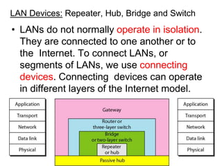
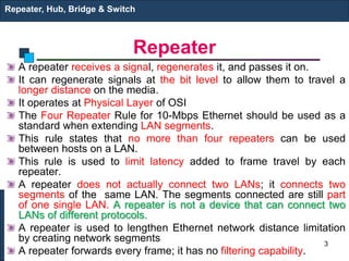
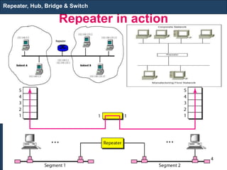
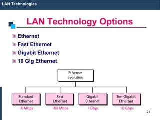
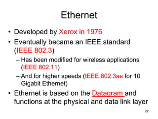
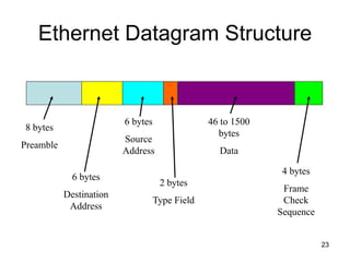
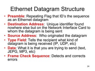
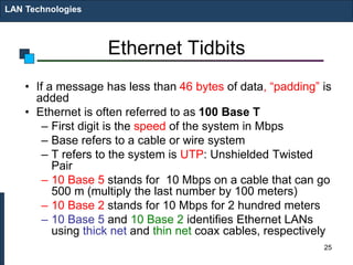
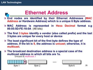
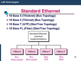
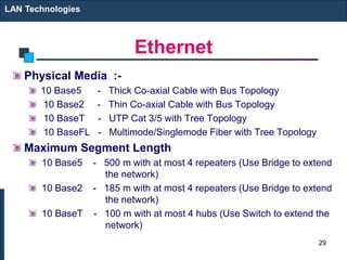
Repeater, HUB, Bridge & Switch
LAN and WAN Technologies
1
Chapter 5
LAN Devices: Repeater, Hub, Bridge and Switch
• LANs do not normally operate in isolation.
They are connected to one another or to
the Internet. To connect LANs, or
segments of LANs, we use connecting
devices. Connecting devices can operate
in different layers of the Internet model.
2
Repeater
A repeater receives a signal, regenerates it, and passes it on.
It can regenerate signals at the bit level to allow them to travel a
longer distance on the media.
It operates at Physical Layer of OSI
The Four Repeater Rule for 10-Mbps Ethernet should be used as a
standard when extending LAN segments.
This rule states that no more than four repeaters can be used
between hosts on a LAN.
This rule is used to limit latency added to frame travel by each
repeater.
A repeater does not actually connect two LANs; it connects two
segments of the same LAN. The segments connected are still part
of one single LAN. A repeater is not a device that can connect two
LANs of different protocols.
A repeater is used to lengthen Ethernet network distance limitation
by creating network segments
A repeater forwards every frame; it has no filtering capability.
Repeater, Hub, Bridge & Switch
3
Repeater in action
Repeater, Hub, Bridge & Switch
4
Hub
Hubs are used to connect
multiple nodes to a single
physical device, which connects
to the network.
Hubs are actually multiport
repeaters.
Using a hub changes the network
topology from a linear bus, to a
star.
With hubs, data arriving over the
cables to a hub port is
electrically repeated on all the
other ports connected to the
same network segment.
Repeater, Hub, Bridge & Switch
5
Hub
Repeater, Hub, Bridge & Switch
6
Types of Hubs
1. Passive hubs do not amplify the electrical signal of incoming packets
before broadcasting them out to the network. It is just a connector. It
connects the wires coming from different branches. In a star-topology
Ethernet LAN, a passive hub is just a point where the signals coming
from different stations collide; the hub is the collision point. This type of
a hub is part of the media; its location in the Internet model is below the
physical layer.
2. Active hubs, a type of hub that can perform amplification, as does a
repeater. Some people use the terms concentrator when referring to a
passive hub and multiport repeater when referring to an active hub.
3. Intelligent hubs add extra features to an active hub that are of particular
importance to businesses. An intelligent hub typically is stackable (built
in such a way that multiple units can be placed one on top of the other to
conserve space). It also typically includes remote management
capabilities via SNMP and virtual LAN (VLAN) support.
Repeater, Hub, Bridge & Switch
7
Bridge
Bridges are used to logically separate network
segments within the same network.
They operate at the OSI physical and data link
layer and are independent of higher-layer
protocols.
As a data link layer device, the bridge can
check the physical (MAC) addresses (source
and destination) contained in the frame.
The function of the bridge is to make intelligent
decisions about whether or not to pass signals
on to the next segment of a network.
When a bridge receives a frame on the network,
the destination MAC address is looked up in
the bridge table to determine whether to filter,
flood, or copy the frame onto another segment
Broadcast Packets are forwarded to all
directions
Repeater, Hub, Bridge & Switch
8
Filtering: A bridge has filtering capability. It can check the
destination address of a frame and decide if the frame should
be forwarded or dropped. If the frame is to be forwarded, the
decision must specify the port. A bridge has a table that maps
addresses to ports.
9
…
In the previous figure, if a frame destined for
station 712B13456142 arrives at port 1, the bridge
consults its table to find the departing port.
According to its table, frames for 712B13456142
leave through port 1; therefore, there is no need
for forwarding, and the frame is dropped. On the
other hand, if a frame for 712B13456141 arrives
at port 2, the departing port is port 1 and the frame
is forwarded. In the first case, LAN 2 remains free
of traffic; in the second case, both LANs have
traffic.
10
MAC Address Learning
• Bridges MAC table can be static or dynamic.
• To make a table dynamic, we need a bridge
that gradually learns from the frame
movements. To do this, the bridge inspects
both the destination and the source
addresses. The destination address is used
for the forwarding decision (table lookup); the
source address is used for adding entries to
the table and for updating purposes.
11
Learning Process – Example
12
1. When station A sends a frame to station D, the bridge does
not have an entry for either D or A. The frame goes out from
all three ports; the frame floods the network. However, by
looking at the source address, the bridge learns that station A
must be located on the LAN connected to port 1. This means
that frames destined for A, in the future, must be sent out
through port 1. The bridge adds this entry to its table. The
table has its first entry now.
2. When station E sends a frame to station A, the bridge has an
entry for A, so it forwards the frame only to port 1. There is no
flooding. In addition, it uses the source address of the frame,
E, to add a second entry to the table.
3. When station B sends a frame to C, the bridge has no entry
for C, so once again it floods the network and adds one more
entry to the table.
4. The process of learning continues as the bridge forwards
frames.
13
Quiz3 (g9-10): in the following diagram, if the following series of data
transmission occurs, show how the Bridge table is built and tell if
filtering or flooding is done in every step. Use A,B,C.. As MAC
addresses and 1,2,3 as port numbers:
A-G; G-D; C-D; F-G
14
Looping Problem in bridges
• A transparent bridge works fine as far as no
redundant bridge in the network
15
…
1. Station A sends a frame to station D. The tables of both bridges
are empty. Both forward the frame and update their tables based
on the source address A.
2. Now there are two copies of the frame on LAN 2. The copy sent
out by bridge 1 is received by bridge 2, which does not have any
information about the destination address D; it floods the bridge.
The copy sent out by bridge 2 is received by bridge 1 and is sent
out for lack of information about D. Note that each frame is
handled separately because bridges, as two nodes on a network
sharing the medium, use an access method such as CSMA/CD.
The tables of both bridges are updated, but still there is no
information for destination D.
3. Now there are two copies of the frame on LAN 1. Step 2 is
repeated, and both copies flood the network.
4. The process continues on and on. Note that bridges are also
repeaters and regenerate frames. So in each iteration, there are
newly generated fresh copies of the frames.
Reading Assignment: To solve the looping problem, the IEEE specification
requires that bridges use the spanning tree algorithm to create a loopless
topology. Read About spanning tree algorithm 16
Switch
Switches are Multiport Bridges.
Switches provide a unique network segment on each
port, thereby separating collision domains.
Today, network designers are replacing hubs in their
wiring closets with switches to increase their network
performance and bandwidth while protecting their
existing wiring investments.
Like bridges, switches learn certain information about
the data packets that are received from various
computers on the network.
Switches use this information to build forwarding
tables to determine the destination of data being sent
by one computer to another computer on the network.
Repeater, Hub, Bridge & Switch
17
Switches: Dedicated Access
Hosts have direct connection to switch
Full Duplex: No collisions
Switching: A-to-A’ and B-to-B’ simultaneously, no
collisions
Switches can be cascaded to expand the network
Repeater, Hub, Bridge & Switch
A’
B’
18
Two/three-layer switches
• When we use the term switch, we must be careful because a
switch can mean two different things. We must clarify the
term by adding the level at which the device operates.
• We can have a two-layer switch or a three-layer switch. A
three-layer switch is used at the network layer; it is a kind of
router.
• The two-layer switch performs at the physical and data link
layers.
• A two-layer switch is a bridge, a bridge with many ports and a
design that allows better (faster) performance. A bridge with
a few ports can connect a few LANs together.
• A bridge with many ports may be able to allocate a unique
port to each station, with each station on its own independent
entity. This means no competing traffic (no Collision)
Repeater, Hub, Bridge & Switch
19
Types of Switches
1.Cut-through switch
Cut-through switch is a packet switch wherein the switch starts
forwarding that frame (or packet) before the whole frame has
been received, normally as soon as the destination address is
processed. A cut-through switch can achieve the lowest
forwarding delays, but it propagates errors from one LAN to
another, because errors can only be detected at the end of each
frame. In other words, this technique reduces latency through the
switch, but decreases reliability.
2.Store and Forward Switch
A switching device that stores a complete incoming data packet
before it is sent out. Such switches are used when incoming and
outgoing speeds differ
Repeater, Hub, Bridge & Switch
20
LAN Technology Options
Ethernet
Fast Ethernet
Gigabit Ethernet
10 Gig Ethernet
LAN Technologies
21
Ethernet
• Developed by Xerox in 1976
• Eventually became an IEEE standard
(IEEE 802.3)
– Has been modified for wireless applications
(IEEE 802.11)
– And for higher speeds (IEEE 802.3ae for 10
Gigabit Ethernet)
• Ethernet is based on the Datagram and
functions at the physical and data link layer
22
Ethernet Datagram Structure
8 bytes
Preamble
6 bytes
Destination
Address
6 bytes
Source
Address
2 bytes
Type Field
4 bytes
Frame
Check
Sequence
46 to 1500
bytes
Data
23
Ethernet Datagram Structure
• Preamble: Repeating Flag that ID’s the sequence
as an Ethernet datagram
• Destination Address: Unique identifier found
nowhere else but on the Network Interface Card to
whom the datagram is being sent
• Source Address: Who originated the datagram
• Type Field: Tells the recipient what kind of
datagram is being received (IP, UDP, etc)
• Data: What it is that you are trying to send (text,
JEPG, MP3, etc)
• Frame Check Sequence: Detects and corrects
errors
24
Ethernet Tidbits
• If a message has less than 46 bytes of data, “padding” is
added
• Ethernet is often referred to as 100 Base T
– First digit is the speed of the system in Mbps
– Base refers to a cable or wire system
– T refers to the system is UTP: Unshielded Twisted
Pair
– 10 Base 5 stands for 10 Mbps on a cable that can go
500 m (multiply the last number by 100 meters)
– 10 Base 2 stands for 10 Mbps for 2 hundred meters
– 10 Base 5 and 10 Base 2 identifies Ethernet LANs
using thick net and thin net coax cables, respectively
LAN Technologies
25
Ethernet Address
End nodes are identified by their Ethernet Addresses (MAC
Address or Hardware Address) which is a unique 6 Byte address.
MAC Address is represented in Hexa Decimal format e.g
00:05:5D:FE:10:0A (48 bits)
The first 3 bytes identify a vendor (also called prefix) and the last
3 bytes are unique for every host or device
The least significant bit of the first byte defines the type of
address. If the bit is 0, the address is unicast; otherwise, it is
multicast.
The broadcast destination address is a special case of the
multicast address in which all bits are 1s.
LAN Technologies
26
Quiz 3(g3-4)
• Define the type of the following destination
addresses:
– a.4A:30:10:21:10:1A
– b. 47:20:1B:2E:08:E7
– c. FF:FF:FF:FF:FF:FF
Solution
To find the type of the address, we need to look at the second
hexadecimal digit from the left. If it is even, the address is unicast. If it
is odd, the address is multicast. If all digits are F’s, the address is
broadcast. Therefore, we have the following:
a. This is a unicast address because A in binary is 1010.
b. This is a multicast address because 7 in binary is 0111.
c. This is a broadcast address because all digits are F’s.
27
Standard Ethernet
10 Base 5 (Thicknet) (Bus Topology)
10 Base 2 (Thinnet) (Bus Topology)
10 Base T (UTP) (Star/Tree Topology)
10 Base FL (Fiber) (Star/Tree Topology)
LAN Technologies
28
Ethernet
Physical Media :-
10 Base5 - Thick Co-axial Cable with Bus Topology
10 Base2 - Thin Co-axial Cable with Bus Topology
10 BaseT - UTP Cat 3/5 with Tree Topology
10 BaseFL - Multimode/Singlemode Fiber with Tree Topology
Maximum Segment Length
10 Base5 - 500 m with at most 4 repeaters (Use Bridge to extend
the network)
10 Base2 - 185 m with at most 4 repeaters (Use Bridge to extend
the network)
10 BaseT - 100 m with at most 4 hubs (Use Switch to extend the
network)
LAN Technologies
29
Fast Ethernet
100 Mbps bandwidth
Uses same CSMA/CD media access protocol and
packet format as in Ethernet.
100BaseTX (UTP) and 100BaseFX (Fiber) standards
Physical media :-
100 BaseTX - UTP Cat 5e
100 BaseFX - Multimode / Singlemode Fiber
Full Duplex/Half Duplex operations.
LAN Technologies
30
Fast Ethernet
Provision for Auto-Negotiation of media speed:
10 Mbps or 100Mbps (popularly available for copper
media only).
Maximum Segment Length
100 Base TX - 100 m
100 Base FX - 2 Km (Multimode Fiber)
100 Base FX - 20 km (Singlemode Fiber)
LAN Technologies
31
Gigabit Ethernet
1 Gbps bandwidth.
Uses same CSMA/CD media access protocol as in
Ethernet and is backward compatible (10/100/100
modules are available).
1000BaseT (UTP), 1000BaseSX (Multimode Fiber)
and 1000BaseLX (Multimode/Singlemode Fiber)
standards.
Maximum Segment Length
1000 Base T - 100m (Cat 5e/6)
1000 Base SX - 275 m (Multimode Fiber)
1000 Base LX - 512 m (Multimode Fiber)
1000 Base LX - 20 Km (Singlemode Fiber)
1000 Base LH - 80 Km (Singlemode Fiber)
LAN Technologies
32
10 Gig Ethernet
10 Gbps bandwidth.
Uses same CSMA/CD media access protocol as in
Ethernet.
Maximum Segment Length
10GBase-T - Not available
10GBase-LR - 10 Km (Singlemode Fiber)
10GBase-ER - 40 Km (Singlemode Fiber)
LAN Technologies
33

chapter 5.1.pptx

  • 1.
    Repeater, HUB, Bridge& Switch LAN and WAN Technologies 1 Chapter 5
  • 2.
    LAN Devices: Repeater,Hub, Bridge and Switch • LANs do not normally operate in isolation. They are connected to one another or to the Internet. To connect LANs, or segments of LANs, we use connecting devices. Connecting devices can operate in different layers of the Internet model. 2
  • 3.
    Repeater A repeater receivesa signal, regenerates it, and passes it on. It can regenerate signals at the bit level to allow them to travel a longer distance on the media. It operates at Physical Layer of OSI The Four Repeater Rule for 10-Mbps Ethernet should be used as a standard when extending LAN segments. This rule states that no more than four repeaters can be used between hosts on a LAN. This rule is used to limit latency added to frame travel by each repeater. A repeater does not actually connect two LANs; it connects two segments of the same LAN. The segments connected are still part of one single LAN. A repeater is not a device that can connect two LANs of different protocols. A repeater is used to lengthen Ethernet network distance limitation by creating network segments A repeater forwards every frame; it has no filtering capability. Repeater, Hub, Bridge & Switch 3
  • 4.
    Repeater in action Repeater,Hub, Bridge & Switch 4
  • 5.
    Hub Hubs are usedto connect multiple nodes to a single physical device, which connects to the network. Hubs are actually multiport repeaters. Using a hub changes the network topology from a linear bus, to a star. With hubs, data arriving over the cables to a hub port is electrically repeated on all the other ports connected to the same network segment. Repeater, Hub, Bridge & Switch 5
  • 6.
  • 7.
    Types of Hubs 1.Passive hubs do not amplify the electrical signal of incoming packets before broadcasting them out to the network. It is just a connector. It connects the wires coming from different branches. In a star-topology Ethernet LAN, a passive hub is just a point where the signals coming from different stations collide; the hub is the collision point. This type of a hub is part of the media; its location in the Internet model is below the physical layer. 2. Active hubs, a type of hub that can perform amplification, as does a repeater. Some people use the terms concentrator when referring to a passive hub and multiport repeater when referring to an active hub. 3. Intelligent hubs add extra features to an active hub that are of particular importance to businesses. An intelligent hub typically is stackable (built in such a way that multiple units can be placed one on top of the other to conserve space). It also typically includes remote management capabilities via SNMP and virtual LAN (VLAN) support. Repeater, Hub, Bridge & Switch 7
  • 8.
    Bridge Bridges are usedto logically separate network segments within the same network. They operate at the OSI physical and data link layer and are independent of higher-layer protocols. As a data link layer device, the bridge can check the physical (MAC) addresses (source and destination) contained in the frame. The function of the bridge is to make intelligent decisions about whether or not to pass signals on to the next segment of a network. When a bridge receives a frame on the network, the destination MAC address is looked up in the bridge table to determine whether to filter, flood, or copy the frame onto another segment Broadcast Packets are forwarded to all directions Repeater, Hub, Bridge & Switch 8
  • 9.
    Filtering: A bridgehas filtering capability. It can check the destination address of a frame and decide if the frame should be forwarded or dropped. If the frame is to be forwarded, the decision must specify the port. A bridge has a table that maps addresses to ports. 9
  • 10.
    … In the previousfigure, if a frame destined for station 712B13456142 arrives at port 1, the bridge consults its table to find the departing port. According to its table, frames for 712B13456142 leave through port 1; therefore, there is no need for forwarding, and the frame is dropped. On the other hand, if a frame for 712B13456141 arrives at port 2, the departing port is port 1 and the frame is forwarded. In the first case, LAN 2 remains free of traffic; in the second case, both LANs have traffic. 10
  • 11.
    MAC Address Learning •Bridges MAC table can be static or dynamic. • To make a table dynamic, we need a bridge that gradually learns from the frame movements. To do this, the bridge inspects both the destination and the source addresses. The destination address is used for the forwarding decision (table lookup); the source address is used for adding entries to the table and for updating purposes. 11
  • 12.
  • 13.
    1. When stationA sends a frame to station D, the bridge does not have an entry for either D or A. The frame goes out from all three ports; the frame floods the network. However, by looking at the source address, the bridge learns that station A must be located on the LAN connected to port 1. This means that frames destined for A, in the future, must be sent out through port 1. The bridge adds this entry to its table. The table has its first entry now. 2. When station E sends a frame to station A, the bridge has an entry for A, so it forwards the frame only to port 1. There is no flooding. In addition, it uses the source address of the frame, E, to add a second entry to the table. 3. When station B sends a frame to C, the bridge has no entry for C, so once again it floods the network and adds one more entry to the table. 4. The process of learning continues as the bridge forwards frames. 13
  • 14.
    Quiz3 (g9-10): inthe following diagram, if the following series of data transmission occurs, show how the Bridge table is built and tell if filtering or flooding is done in every step. Use A,B,C.. As MAC addresses and 1,2,3 as port numbers: A-G; G-D; C-D; F-G 14
  • 15.
    Looping Problem inbridges • A transparent bridge works fine as far as no redundant bridge in the network 15
  • 16.
    … 1. Station Asends a frame to station D. The tables of both bridges are empty. Both forward the frame and update their tables based on the source address A. 2. Now there are two copies of the frame on LAN 2. The copy sent out by bridge 1 is received by bridge 2, which does not have any information about the destination address D; it floods the bridge. The copy sent out by bridge 2 is received by bridge 1 and is sent out for lack of information about D. Note that each frame is handled separately because bridges, as two nodes on a network sharing the medium, use an access method such as CSMA/CD. The tables of both bridges are updated, but still there is no information for destination D. 3. Now there are two copies of the frame on LAN 1. Step 2 is repeated, and both copies flood the network. 4. The process continues on and on. Note that bridges are also repeaters and regenerate frames. So in each iteration, there are newly generated fresh copies of the frames. Reading Assignment: To solve the looping problem, the IEEE specification requires that bridges use the spanning tree algorithm to create a loopless topology. Read About spanning tree algorithm 16
  • 17.
    Switch Switches are MultiportBridges. Switches provide a unique network segment on each port, thereby separating collision domains. Today, network designers are replacing hubs in their wiring closets with switches to increase their network performance and bandwidth while protecting their existing wiring investments. Like bridges, switches learn certain information about the data packets that are received from various computers on the network. Switches use this information to build forwarding tables to determine the destination of data being sent by one computer to another computer on the network. Repeater, Hub, Bridge & Switch 17
  • 18.
    Switches: Dedicated Access Hostshave direct connection to switch Full Duplex: No collisions Switching: A-to-A’ and B-to-B’ simultaneously, no collisions Switches can be cascaded to expand the network Repeater, Hub, Bridge & Switch A’ B’ 18
  • 19.
    Two/three-layer switches • Whenwe use the term switch, we must be careful because a switch can mean two different things. We must clarify the term by adding the level at which the device operates. • We can have a two-layer switch or a three-layer switch. A three-layer switch is used at the network layer; it is a kind of router. • The two-layer switch performs at the physical and data link layers. • A two-layer switch is a bridge, a bridge with many ports and a design that allows better (faster) performance. A bridge with a few ports can connect a few LANs together. • A bridge with many ports may be able to allocate a unique port to each station, with each station on its own independent entity. This means no competing traffic (no Collision) Repeater, Hub, Bridge & Switch 19
  • 20.
    Types of Switches 1.Cut-throughswitch Cut-through switch is a packet switch wherein the switch starts forwarding that frame (or packet) before the whole frame has been received, normally as soon as the destination address is processed. A cut-through switch can achieve the lowest forwarding delays, but it propagates errors from one LAN to another, because errors can only be detected at the end of each frame. In other words, this technique reduces latency through the switch, but decreases reliability. 2.Store and Forward Switch A switching device that stores a complete incoming data packet before it is sent out. Such switches are used when incoming and outgoing speeds differ Repeater, Hub, Bridge & Switch 20
  • 21.
    LAN Technology Options Ethernet FastEthernet Gigabit Ethernet 10 Gig Ethernet LAN Technologies 21
  • 22.
    Ethernet • Developed byXerox in 1976 • Eventually became an IEEE standard (IEEE 802.3) – Has been modified for wireless applications (IEEE 802.11) – And for higher speeds (IEEE 802.3ae for 10 Gigabit Ethernet) • Ethernet is based on the Datagram and functions at the physical and data link layer 22
  • 23.
    Ethernet Datagram Structure 8bytes Preamble 6 bytes Destination Address 6 bytes Source Address 2 bytes Type Field 4 bytes Frame Check Sequence 46 to 1500 bytes Data 23
  • 24.
    Ethernet Datagram Structure •Preamble: Repeating Flag that ID’s the sequence as an Ethernet datagram • Destination Address: Unique identifier found nowhere else but on the Network Interface Card to whom the datagram is being sent • Source Address: Who originated the datagram • Type Field: Tells the recipient what kind of datagram is being received (IP, UDP, etc) • Data: What it is that you are trying to send (text, JEPG, MP3, etc) • Frame Check Sequence: Detects and corrects errors 24
  • 25.
    Ethernet Tidbits • Ifa message has less than 46 bytes of data, “padding” is added • Ethernet is often referred to as 100 Base T – First digit is the speed of the system in Mbps – Base refers to a cable or wire system – T refers to the system is UTP: Unshielded Twisted Pair – 10 Base 5 stands for 10 Mbps on a cable that can go 500 m (multiply the last number by 100 meters) – 10 Base 2 stands for 10 Mbps for 2 hundred meters – 10 Base 5 and 10 Base 2 identifies Ethernet LANs using thick net and thin net coax cables, respectively LAN Technologies 25
  • 26.
    Ethernet Address End nodesare identified by their Ethernet Addresses (MAC Address or Hardware Address) which is a unique 6 Byte address. MAC Address is represented in Hexa Decimal format e.g 00:05:5D:FE:10:0A (48 bits) The first 3 bytes identify a vendor (also called prefix) and the last 3 bytes are unique for every host or device The least significant bit of the first byte defines the type of address. If the bit is 0, the address is unicast; otherwise, it is multicast. The broadcast destination address is a special case of the multicast address in which all bits are 1s. LAN Technologies 26
  • 27.
    Quiz 3(g3-4) • Definethe type of the following destination addresses: – a.4A:30:10:21:10:1A – b. 47:20:1B:2E:08:E7 – c. FF:FF:FF:FF:FF:FF Solution To find the type of the address, we need to look at the second hexadecimal digit from the left. If it is even, the address is unicast. If it is odd, the address is multicast. If all digits are F’s, the address is broadcast. Therefore, we have the following: a. This is a unicast address because A in binary is 1010. b. This is a multicast address because 7 in binary is 0111. c. This is a broadcast address because all digits are F’s. 27
  • 28.
    Standard Ethernet 10 Base5 (Thicknet) (Bus Topology) 10 Base 2 (Thinnet) (Bus Topology) 10 Base T (UTP) (Star/Tree Topology) 10 Base FL (Fiber) (Star/Tree Topology) LAN Technologies 28
  • 29.
    Ethernet Physical Media :- 10Base5 - Thick Co-axial Cable with Bus Topology 10 Base2 - Thin Co-axial Cable with Bus Topology 10 BaseT - UTP Cat 3/5 with Tree Topology 10 BaseFL - Multimode/Singlemode Fiber with Tree Topology Maximum Segment Length 10 Base5 - 500 m with at most 4 repeaters (Use Bridge to extend the network) 10 Base2 - 185 m with at most 4 repeaters (Use Bridge to extend the network) 10 BaseT - 100 m with at most 4 hubs (Use Switch to extend the network) LAN Technologies 29
  • 30.
    Fast Ethernet 100 Mbpsbandwidth Uses same CSMA/CD media access protocol and packet format as in Ethernet. 100BaseTX (UTP) and 100BaseFX (Fiber) standards Physical media :- 100 BaseTX - UTP Cat 5e 100 BaseFX - Multimode / Singlemode Fiber Full Duplex/Half Duplex operations. LAN Technologies 30
  • 31.
    Fast Ethernet Provision forAuto-Negotiation of media speed: 10 Mbps or 100Mbps (popularly available for copper media only). Maximum Segment Length 100 Base TX - 100 m 100 Base FX - 2 Km (Multimode Fiber) 100 Base FX - 20 km (Singlemode Fiber) LAN Technologies 31
  • 32.
    Gigabit Ethernet 1 Gbpsbandwidth. Uses same CSMA/CD media access protocol as in Ethernet and is backward compatible (10/100/100 modules are available). 1000BaseT (UTP), 1000BaseSX (Multimode Fiber) and 1000BaseLX (Multimode/Singlemode Fiber) standards. Maximum Segment Length 1000 Base T - 100m (Cat 5e/6) 1000 Base SX - 275 m (Multimode Fiber) 1000 Base LX - 512 m (Multimode Fiber) 1000 Base LX - 20 Km (Singlemode Fiber) 1000 Base LH - 80 Km (Singlemode Fiber) LAN Technologies 32
  • 33.
    10 Gig Ethernet 10Gbps bandwidth. Uses same CSMA/CD media access protocol as in Ethernet. Maximum Segment Length 10GBase-T - Not available 10GBase-LR - 10 Km (Singlemode Fiber) 10GBase-ER - 40 Km (Singlemode Fiber) LAN Technologies 33