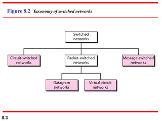
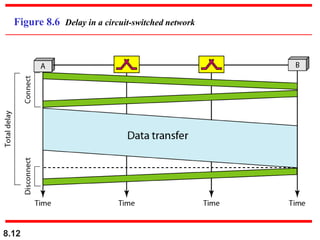
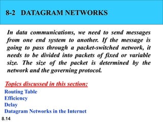
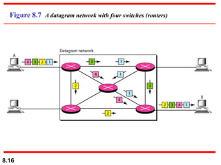
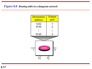
8.1
Switching
8.2
Figure 8.1 Switched network
8.3
Figure 8.2 Taxonomy of switched networks
8.4
8-1 CIRCUIT-SWITCHED NETWORKS
A circuit-switched network consists of a set of switches
connected by physical links. A connection between two
stations is a dedicated path made of one or more links.
However, each connection uses only one dedicated
channel on each link. Each link is normally divided
into n channels by using FDM or TDM.
Three Phases
Efficiency
Delay
Circuit-Switched Technology in Telephone Networks
Topics discussed in this section:
8.5
A circuit-switched network is made of a
set of switches connected by physical
links, in which each link is
divided into n channels.
Note
8.6
Figure 8.3 A trivial circuit-switched network
8.7
In circuit switching, the resources need
to be reserved during the setup phase;
the resources remain dedicated for the
entire duration of data transfer until the
teardown phase.
Note
8.8
As a trivial example, let us use a circuit-switched network
to connect eight telephones in a small area.
Communication is through 4-kHz voice channels. We
assume that each link uses FDM to connect a maximum
of two voice channels. The bandwidth of each link is then
8 kHz. Figure 8.4 shows the situation. Telephone 1 is
connected to telephone 7; 2 to 5; 3 to 8; and 4 to 6. Of
course the situation may change when new connections
are made. The switch controls the connections.
Example 8.1
8.9
Figure 8.4 Circuit-switched network used in Example 8.1
8.10
As another example, consider a circuit-switched network
that connects computers in two remote offices of a private
company. The offices are connected using a T-1 line
leased from a communication service provider. There are
two 4 × 8 (4 inputs and 8 outputs) switches in this
network. For each switch, four output ports are folded
into the input ports to allow communication between
computers in the same office. Four other output ports
allow communication between the two offices. Figure 8.5
shows the situation.
Example 8.2
8.11
Figure 8.5 Circuit-switched network used in Example 8.2
8.12
Figure 8.6 Delay in a circuit-switched network
8.13
Switching at the physical layer in the
traditional telephone network uses
the circuit-switching approach.
Note
8.14
8-2 DATAGRAM NETWORKS
In data communications, we need to send messages
from one end system to another. If the message is
going to pass through a packet-switched network, it
needs to be divided into packets of fixed or variable
size. The size of the packet is determined by the
network and the governing protocol.
Routing Table
Efficiency
Delay
Datagram Networks in the Internet
Topics discussed in this section:
8.15
In a packet-switched network, there
is no resource reservation;
resources are allocated on demand.
Note
8.16
Figure 8.7 A datagram network with four switches (routers)
8.17
Figure 8.8 Routing table in a datagram network
8.18
A switch in a datagram network uses a
routing table that is based on the
destination address.
Note
8.19
The destination address in the header of
a packet in a datagram network
remains the same during the entire
journey of the packet.
Note
8.20
Figure 8.9 Delay in a datagram network
8.21
Switching in the Internet is done by
using the datagram approach
to packet switching at
the network layer.
Note
8.22
8-3 VIRTUAL-CIRCUIT NETWORKS
A virtual-circuit network is a cross between a circuit-
switched network and a datagram network. It has
some characteristics of both.
Addressing
Three Phases
Efficiency
Delay
Circuit-Switched Technology in WANs
Topics discussed in this section:
8.23
Figure 8.10 Virtual-circuit network
8.24
Figure 8.11 Virtual-circuit identifier
8.25
Figure 8.12 Switch and tables in a virtual-circuit network
8.26
Figure 8.13 Source-to-destination data transfer in a virtual-circuit network
8.27
Figure 8.14 Setup request in a virtual-circuit network
8.28
Figure 8.15 Setup acknowledgment in a virtual-circuit network
8.29
In virtual-circuit switching, all packets
belonging to the same source and
destination travel the same path;
but the packets may arrive at the
destination with different delays
if resource allocation is on demand.
Note
8.30
Figure 8.16 Delay in a virtual-circuit network
8.31
Switching at the data link layer in a
switched WAN is normally
implemented by using
virtual-circuit techniques.
Note
8.32
8-4 STRUCTURE OF A SWITCH
We use switches in circuit-switched and packet-
switched networks. In this section, we discuss the
structures of the switches used in each type of
network.
Structure of Circuit Switches
Structure of Packet Switches
Topics discussed in this section:
8.33
Figure 8.17 Crossbar switch with three inputs and four outputs
8.34
Figure 8.18 Multistage switch
8.35
In a three-stage switch, the total
number of crosspoints is
2kN + k(N/n)2
which is much smaller than the number of
crosspoints in a single-stage switch (N2).
Note
8.36
Design a three-stage, 200 × 200 switch (N = 200) with
k = 4 and n = 20.
Solution
In the first stage we have N/n or 10 crossbars, each of size
20 × 4. In the second stage, we have 4 crossbars, each of
size 10 × 10. In the third stage, we have 10 crossbars,
each of size 4 × 20. The total number of crosspoints is
2kN + k(N/n)2, or 2000 crosspoints. This is 5 percent of
the number of crosspoints in a single-stage switch (200 ×
200 = 40,000).
Example 8.3
8.37
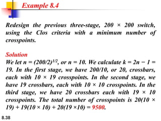
According to the Clos criterion:
n = (N/2)1/2
k > 2n – 1
Crosspoints ≥ 4N [(2N)1/2 – 1]
Note
8.38
Redesign the previous three-stage, 200 × 200 switch,
using the Clos criteria with a minimum number of
crosspoints.
Solution
We let n = (200/2)1/2, or n = 10. We calculate k = 2n − 1 =
19. In the first stage, we have 200/10, or 20, crossbars,
each with 10 × 19 crosspoints. In the second stage, we
have 19 crossbars, each with 10 × 10 crosspoints. In the
third stage, we have 20 crossbars each with 19 × 10
crosspoints. The total number of crosspoints is 20(10 ×
19) + 19(10 × 10) + 20(19 ×10) = 9500.
Example 8.4
8.39
Figure 8.19 Time-slot interchange
8.40
Figure 8.20 Time-space-time switch
8.41
Figure 8.21 Packet switch components
8.42
Figure 8.22 Input port
8.43
Figure 8.23 Output port
8.44
1. A path in a digital circuit-switched network has a data rate of I Mbps. The exchange of
1000 bits is required for the setup and teardown phases. The distance between two parties
is 5000 km. Answer the following questions if the propagataion speed is 2 X 10⁸ m:
a. What is the total delay if 1000 bits of data are exchanged during the data transfer phase?
b. What is the total delay if 100,000 bits of data are exchanged during the data transfer
phase?
c. What is the total delay if 1,000,000 bits of data are exchanged during the data transfer
phase?
d. Find the delay per 1000 bits of data for each of the above cases and compare them.
What can you infer?
2. We mentioned that two types of networks, datagram and virtual-circuit, need a routing
or switching table to find the output port from which the information belonging to a
destination should be sent out, but a circuit-switched network has no need for such a
table. Give the reason for this difference.
Exercises
8.45
3. We need a three-stage space-division switch with N =100. We use 10 crossbars at the first and
third stages and 4 crossbars at the middle stage.
a. Draw the configuration diagram.
b. Calculate the total number of crosspoints.
c. Find the possible number of simultaneous connections.
d. Find the possible number of simultaneous connections if we use one single crossbar (100 x
100).
e. Find the blocking factor, the ratio of the number of connections in c and in d.

Network switching

  • 1.
  • 2.
  • 3.
    8.3 Figure 8.2 Taxonomyof switched networks
  • 4.
    8.4 8-1 CIRCUIT-SWITCHED NETWORKS Acircuit-switched network consists of a set of switches connected by physical links. A connection between two stations is a dedicated path made of one or more links. However, each connection uses only one dedicated channel on each link. Each link is normally divided into n channels by using FDM or TDM. Three Phases Efficiency Delay Circuit-Switched Technology in Telephone Networks Topics discussed in this section:
  • 5.
    8.5 A circuit-switched networkis made of a set of switches connected by physical links, in which each link is divided into n channels. Note
  • 6.
    8.6 Figure 8.3 Atrivial circuit-switched network
  • 7.
    8.7 In circuit switching,the resources need to be reserved during the setup phase; the resources remain dedicated for the entire duration of data transfer until the teardown phase. Note
  • 8.
    8.8 As a trivialexample, let us use a circuit-switched network to connect eight telephones in a small area. Communication is through 4-kHz voice channels. We assume that each link uses FDM to connect a maximum of two voice channels. The bandwidth of each link is then 8 kHz. Figure 8.4 shows the situation. Telephone 1 is connected to telephone 7; 2 to 5; 3 to 8; and 4 to 6. Of course the situation may change when new connections are made. The switch controls the connections. Example 8.1
  • 9.
    8.9 Figure 8.4 Circuit-switchednetwork used in Example 8.1
  • 10.
    8.10 As another example,consider a circuit-switched network that connects computers in two remote offices of a private company. The offices are connected using a T-1 line leased from a communication service provider. There are two 4 × 8 (4 inputs and 8 outputs) switches in this network. For each switch, four output ports are folded into the input ports to allow communication between computers in the same office. Four other output ports allow communication between the two offices. Figure 8.5 shows the situation. Example 8.2
  • 11.
    8.11 Figure 8.5 Circuit-switchednetwork used in Example 8.2
  • 12.
    8.12 Figure 8.6 Delayin a circuit-switched network
  • 13.
    8.13 Switching at thephysical layer in the traditional telephone network uses the circuit-switching approach. Note
  • 14.
    8.14 8-2 DATAGRAM NETWORKS Indata communications, we need to send messages from one end system to another. If the message is going to pass through a packet-switched network, it needs to be divided into packets of fixed or variable size. The size of the packet is determined by the network and the governing protocol. Routing Table Efficiency Delay Datagram Networks in the Internet Topics discussed in this section:
  • 15.
    8.15 In a packet-switchednetwork, there is no resource reservation; resources are allocated on demand. Note
  • 16.
    8.16 Figure 8.7 Adatagram network with four switches (routers)
  • 17.
    8.17 Figure 8.8 Routingtable in a datagram network
  • 18.
    8.18 A switch ina datagram network uses a routing table that is based on the destination address. Note
  • 19.
    8.19 The destination addressin the header of a packet in a datagram network remains the same during the entire journey of the packet. Note
  • 20.
    8.20 Figure 8.9 Delayin a datagram network
  • 21.
    8.21 Switching in theInternet is done by using the datagram approach to packet switching at the network layer. Note
  • 22.
    8.22 8-3 VIRTUAL-CIRCUIT NETWORKS Avirtual-circuit network is a cross between a circuit- switched network and a datagram network. It has some characteristics of both. Addressing Three Phases Efficiency Delay Circuit-Switched Technology in WANs Topics discussed in this section:
  • 23.
  • 24.
  • 25.
    8.25 Figure 8.12 Switchand tables in a virtual-circuit network
  • 26.
    8.26 Figure 8.13 Source-to-destinationdata transfer in a virtual-circuit network
  • 27.
    8.27 Figure 8.14 Setuprequest in a virtual-circuit network
  • 28.
    8.28 Figure 8.15 Setupacknowledgment in a virtual-circuit network
  • 29.
    8.29 In virtual-circuit switching,all packets belonging to the same source and destination travel the same path; but the packets may arrive at the destination with different delays if resource allocation is on demand. Note
  • 30.
    8.30 Figure 8.16 Delayin a virtual-circuit network
  • 31.
    8.31 Switching at thedata link layer in a switched WAN is normally implemented by using virtual-circuit techniques. Note
  • 32.
    8.32 8-4 STRUCTURE OFA SWITCH We use switches in circuit-switched and packet- switched networks. In this section, we discuss the structures of the switches used in each type of network. Structure of Circuit Switches Structure of Packet Switches Topics discussed in this section:
  • 33.
    8.33 Figure 8.17 Crossbarswitch with three inputs and four outputs
  • 34.
  • 35.
    8.35 In a three-stageswitch, the total number of crosspoints is 2kN + k(N/n)2 which is much smaller than the number of crosspoints in a single-stage switch (N2). Note
  • 36.
    8.36 Design a three-stage,200 × 200 switch (N = 200) with k = 4 and n = 20. Solution In the first stage we have N/n or 10 crossbars, each of size 20 × 4. In the second stage, we have 4 crossbars, each of size 10 × 10. In the third stage, we have 10 crossbars, each of size 4 × 20. The total number of crosspoints is 2kN + k(N/n)2, or 2000 crosspoints. This is 5 percent of the number of crosspoints in a single-stage switch (200 × 200 = 40,000). Example 8.3
  • 37.
    8.37 According to theClos criterion: n = (N/2)1/2 k > 2n – 1 Crosspoints ≥ 4N [(2N)1/2 – 1] Note
  • 38.
    8.38 Redesign the previousthree-stage, 200 × 200 switch, using the Clos criteria with a minimum number of crosspoints. Solution We let n = (200/2)1/2, or n = 10. We calculate k = 2n − 1 = 19. In the first stage, we have 200/10, or 20, crossbars, each with 10 × 19 crosspoints. In the second stage, we have 19 crossbars, each with 10 × 10 crosspoints. In the third stage, we have 20 crossbars each with 19 × 10 crosspoints. The total number of crosspoints is 20(10 × 19) + 19(10 × 10) + 20(19 ×10) = 9500. Example 8.4
  • 39.
  • 40.
  • 41.
    8.41 Figure 8.21 Packetswitch components
  • 42.
  • 43.
  • 44.
    8.44 1. A pathin a digital circuit-switched network has a data rate of I Mbps. The exchange of 1000 bits is required for the setup and teardown phases. The distance between two parties is 5000 km. Answer the following questions if the propagataion speed is 2 X 10⁸ m: a. What is the total delay if 1000 bits of data are exchanged during the data transfer phase? b. What is the total delay if 100,000 bits of data are exchanged during the data transfer phase? c. What is the total delay if 1,000,000 bits of data are exchanged during the data transfer phase? d. Find the delay per 1000 bits of data for each of the above cases and compare them. What can you infer? 2. We mentioned that two types of networks, datagram and virtual-circuit, need a routing or switching table to find the output port from which the information belonging to a destination should be sent out, but a circuit-switched network has no need for such a table. Give the reason for this difference. Exercises
  • 45.
    8.45 3. We needa three-stage space-division switch with N =100. We use 10 crossbars at the first and third stages and 4 crossbars at the middle stage. a. Draw the configuration diagram. b. Calculate the total number of crosspoints. c. Find the possible number of simultaneous connections. d. Find the possible number of simultaneous connections if we use one single crossbar (100 x 100). e. Find the blocking factor, the ratio of the number of connections in c and in d.