Downloaded 15 times


![Note
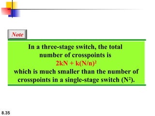
According to the Clos criterion:
n = (N/2)1/2
k > 2n – 1
Crosspoints ≥ 4N [(2N)1/2 – 1]
8.37](https://image.slidesharecdn.com/ch08-131114213951-phpapp01/85/Ch08-37-320.jpg)


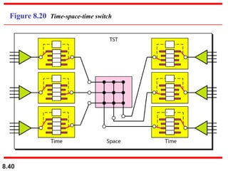


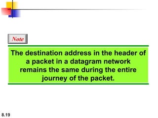
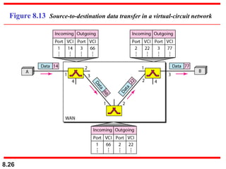
This document discusses different types of switched networks including circuit-switched networks, datagram networks, and virtual-circuit networks. It describes the key characteristics of each type, such as how resources are reserved and allocated, addressing schemes, routing approaches, and delay considerations. The document also covers the structure of switches used in different networks, comparing crossbar, multistage, and space-division switches. Examples are provided to illustrate three-stage switch design and routing in banyan switches.