Downloaded 38 times

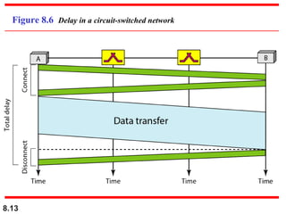
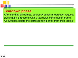
![Multistage Drawback
Blocking during periods of heavy traffic.
Blocking refers to times when one input cannot be connected to an output because
there is no path available between them –all possible intermediate switches are
occupied
Note
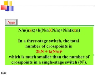
According to the Clos criterion:
condition for nonblocking
n = (N/2)1/2
k > 2n – 1
Crosspoints (clos) ≥ 4N [(2N)1/2 – 1]
Crosspoints
8.42
= 2kN + k(N/n)2](https://image.slidesharecdn.com/ch08-131230221442-phpapp02/85/Ch08-42-320.jpg)

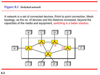
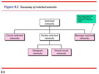
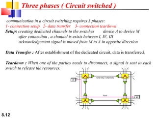
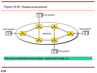
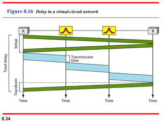
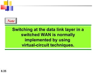
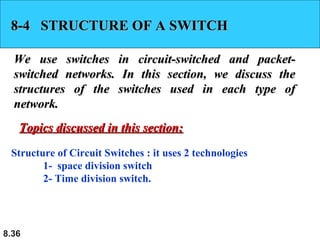
A circuit-switched network uses dedicated connections between nodes, requiring three phases of connection setup, data transfer, and teardown. Resources are reserved during setup. In contrast, a packet-switched or datagram network divides messages into packets that are routed independently through the network without resource reservation. Each switch uses a routing table to determine the next hop based on the packet's destination address. A virtual-circuit network combines aspects of circuit and datagram switching by establishing virtual circuits with resource reservation but packetizing the data. Switches in these networks use various architectures like crossbar, multistage, time-division, and space-division designs to connect inputs to outputs.