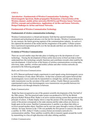
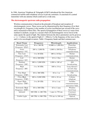
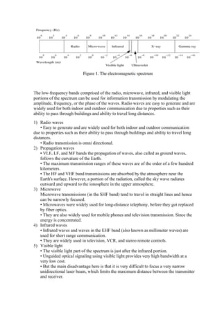
SlideShare a Scribd company logo
1 of 13
Download to read offline
UNIT I:
Introduction : Fundamentals of Wireless Communication Technology, The
Electromagnetic Spectrum, Radio propagation Mechanisms ,Characteristics of the
Wireless channel , mobile ad hoc networks (MANETs) and Wireless Sensor Networks
(WSNs): concepts and architectures, Applications of Ad Hoc and Sensor Networks,
Design Challenges in Ad hoc and Sensor Networks.
Fundamentals of Wireless Communication Technology
Fundamentals of wireless communication technology:
Wireless Communication is a broad and dynamic field that has spurred tremendous
excitement and technological advance over the last few decades. Wireless Communication is,
by any measure, the fastest growing segment of the communications industry. As such as it
has captured the attention of the media and the imagination of the public. Cellular systems
have experienced exponential growth over the last decade and there are currently about two
billion users worldwide.
Evolution of Wireless Communication
There are several smaller steps that take place in leading up to the development of a new
technology . Tracing the development of these earlier discoveries in brief can help us better
understand how this technology actually functions and contributes towards what could be the
next development. A brief review of the history of wireless communications covering radio,
television, radar, satellite, wireless and mobile cellular and other wireless networks are
presented in the following paragraph.
Radio and Television Communications
In 1874, Marconi performed simple experiments to send signals using electromagnetic waves
at short distances of only about 100 meters. At that time scientists and experts believed that
electromagnetic waves could only be transmitted in a straight line, and the main obstacle to
radio transmission was the curvature of the earth’s surface. Finally Marconi successfully
experimented to prove that electromagnetic wave transmission was possible between two
distant points even through obstacles in between.
Radar Communication
Radar has been recognized as one of the greatest scientific developments of the first half of
the 20th century. The first practical radar system was produced in 1935 by the British
physicist Robert Watson-Watt. Radar is an active remote-sensing system that operates on the
principle of echoes. A Radar display shows a map like picture of the area being scanned. The
centre of the picture corresponds to the radar antenna and the radar echoes are shown as
bright spots on the screen. Satellite Communication A satellite is an object that orbits or
revolves around another object. Satellites can be sent into space through a variety of launch
vehicles. Sir Isaac Newton in the 1720s was probably the first person to conceive the idea of
a satellite. In 1945, Arthur C Clarke a science fiction envisioned a network of a
communication satellite. Three satellites would be able to transmit signals around the world
by transmitting in a line-of-sight direction with other orbiting satellites.
Cellular Communication
In 1946, American Telephone & Telegraph (AT&T) introduced the first American
commercial mobile radio telephone service to private customers. It consisted of a central
transmitter with one antenna which could serve a wide area.
The electromagnetic spectrum radio propagation:
Wireless communication is based on the principle of broadcast and reception of
electromagnetic waves. These waves can be characterized by their frequency (f) or their
wavelength (λ). Frequency is the number of cycles (oscillations) per second of the wave
and is measured in Hertz (Hz). The speed of propagation of these waves (c) varies from
medium to medium, except in a vacuum where all electromagnetic waves travel at the
same speed, the speed of light. The relation between the above parameters can be given as
c = λ × f where c is the speed of light (3 × 10⁸m/s), f is the frequency of the wave in Hz,
and λ is its wavelength in meters. Table 1 Frequency bands and their common uses
The low-frequency bands comprised of the radio, microwave, infrared, and visible light
portions of the spectrum can be used for information transmission by modulating the
amplitude, frequency, or the phase of the waves. Radio waves are easy to generate and are
widely used for both indoor and outdoor communication due to properties such as their
ability to pass through buildings and ability to travel long distances.
1) Radio waves
• Easy to generate and are widely used for both indoor and outdoor communication
due to properties such as their ability to pass through buildings and ability to travel long
distances.
• Radio transmission is omni directional.
2) Propagation waves
• VLF, LF, and MF bands the propagation of waves, also called as ground waves,
follows the curvature of the Earth.
• The maximum transmission ranges of these waves are of the order of a few hundred
kilometers.
• The HF and VHF band transmissions are absorbed by the atmosphere near the
Earth's surface. However, a portion of the radiation, called the sky wave radiates
outward and upward to the ionosphere in the upper atmosphere.
3) Microwave
Microwave transmissions (in the SHF band) tend to travel in straight lines and hence
can be narrowly focused.
• Microwaves were widely used for long-distance telephony, before they got replaced
by fiber optics.
• They are also widely used for mobile phones and television transmission. Since the
energy is concentrated.
4) Infrared waves
• Infrared waves and waves in the EHF band (also known as millimeter waves) are
used for short range communication.
• They are widely used in television, VCR, and stereo remote controls.
5) Visible light
• The visible light part of the spectrum is just after the infrared portion.
• Unguided optical signaling using visible light provides very high bandwidth at a
very low cost.
• But the main disadvantage here is that it is very difficult to focus a very narrow
unidirectional laser beam, which limits the maximum distance between the transmitter
and receiver.
In the VLF, LF, and MF bands the propagation of waves, also called as ground
waves, follows the curvature of the Earth. The maximum transmission ranges of these
waves are of the order of a few hundred kilometers. They are used for low bandwidth
transmissions such as amplitude modulated.
Radio Propagation Mechanisms
Radio waves generally experience the following three propagation mechanisms:
• Reflection:
When the propagating radio wave hits an object which is very large compared to its
wavelength (such as the surface of the Earth, or tall buildings), the wave gets reflected by
that object. Reflection causes a phase shift of 180 degrees between the incident and the
reflected rays.
• Diffraction:
This propagation effect is undergone by a wave when it hits an impenetrable object. The
wave bends at the edges of the object, thereby propagating in different directions. This
phenomenon is termed as diffraction. The dimensions of the object causing diffraction are
comparable to the wavelength of the wave being diffracted. The bending causes the wave
to reach places behind the object which generally cannot be reached by the line-of-sight
transmission. The amount of diffraction is frequency-dependent, with the lower frequency
waves diffracting more.
• Scattering:
When the wave travels through a medium, which contains many objects with dimensions
small when compared to its wavelength, scattering occurs. The wave gets scattered into
several weaker outgoing signals. In practice, objects such as street signs, lamp posts, and
foliage cause scattering.
Characteristics of wireless channels:
1. Path Loss
• Path loss can be expressed as the ratio of the power of the transmitted signal to the
power of the same signal received by the receiver, on a given path. It is a function of
the propagation distance.
• Path loss is dependent on a number of factors such as the radio frequency used and
the nature of the terrain.
• So, several models are required to describe the variety of transmission
environments.
There are two path loss model, i. Free propagation model ii. Two ray model or two path
model
Free propagation model :
The simplest path loss model in which there is a direct-path signal between the transmitter
and the receiver, with no atmospheric attenuation or multipath components.
The relationship between the transmitted power Pt and the received power Pr is given by
Where Gt and Gr are the transmitter and receiver antenna gains, 1 respectively, in the
direction from the transmitter to the receiver, d is the distance between the transmitter and
receiver, and λ= c/f (is the wavelength of the signal).
Two ray model :
The signal reaches the receiver through two paths, one a line-of sight path, and the other the
path through which the reflected (or refracted, or scattered) wave is received. According to
the two-path model, the received power is given by
Where Pt is the transmitted power, Gt and Gr represent the antenna gains at the transmitter
and the receiver, respectively, d is the distance between the transmitter and receiver, and ht
and hr are the heights of the transmitter and the receiver, respectively.
2. Fading
Fading refers to the fluctuations in signal strength when received at the receiver.
Fading can be classified into two types:
i. Fast fading/small-scale fading
ii. Slow fading/large-scale fading.
i. Fast fading refers to the rapid fluctuations in the amplitude, phase, or multipath
delays of the received signal, due to the interference between multiple versions
(copies) of the same transmitted signal arriving at the receiver at slightly different
times.
 The time between the reception of the first version of the signal and the last
echoed signal is called delay spread. The multipath propagation of the
transmitted signal, which causes fast fading.
 The multipath propagation of the transmitted signal, which causes fast fading.
The multiple signal paths may sometimes add constructively or sometimes
destructively at the receiver, causing a variation in the power level of the
received signal.
ii. Slow fading occurs when objects that partially absorb the transmissions lie between
the transmitter and receiver.
 Slow fading is so called because the duration of the fade may last for multiple seconds
or minutes.
 Slow fading may occur when the receiver is inside a building and the radio wave must
pass through the walls of a building, or when the receiver is temporarily shielded from
the transmitter by a building.
 Slow fading is also referred to as shadow fading since the objects that cause the fade,
which may be large buildings or other structures, block the direct transmission path
from the transmitter to the receiver.
Some common measures to overcome the fading effect are (a) Diversity (b)Adaptive
modulation
(a) Diversity Mechanism
 Based on the fact that independent paths between the same transmitter and
receiver nodes experience independent fading effects. By providing multiple
logical channels between the transmitter and receiver, and sending parts of the
signal over each channel, the error effects due to fading can be compensated.
i. Time diversity mechanisms aim at spreading the data over time so that the
effects of burst errors are minimized.
ii. Frequency diversity mechanisms spread the transmission over a wider
frequency spectrum, or use multiple carriers for transmitting the information.
iii. Space diversity involves the use of different physical transmission paths.
(b) Adaptive Modulation Mechanisms
 The channel characteristics are estimated at the receiver and the estimates are
sent by the receiver to the transmitter through a feedback channel.
 The transmitter adapts its transmissions based on the received channel
estimates in order to counter the errors that could occur due to the
characteristics of the channel. Adaptive techniques are usually very complex
to implement.
3. Interference
 Wireless transmissions have to counter interference from a wide variety of
sources. Two main forms of interference are adjacent channel interference and
co-channel interference.
i. Adjacent channel interference case, signals in nearby frequencies have
components outside their allocated ranges. These components may
interfere with on-going transmissions in the adjacent frequencies. It
can be avoided by carefully introducing guard bands2 between the
allocated frequency ranges.
ii. Co-channel interference, sometimes also referred to as narrow-band
interference, is due to other nearby systems the same transmission
frequency. Narrow-band interference due to frequency reuse in cellular
systems can be minimized with the use of multiuser detection.
Mobile ad hoc networks (MANETs)
MANET stands for Mobile adhoc Network also called as wireless adhoc network or adhoc
wireless network. They consist of set of mobile nodes connected wirelessly in a self
configured, self healing network without having a fixed infrastructure. MANET nodes are
free to move randomly as the network topology changes frequently.
Types of MANET –
1. Vehicular Ad hoc Network (VANETs) –
Enable effective communication with another vehicle or with the roadside
equipments.Intelligent vehicular ad hoc networks(InVANETs) deals with another vehicle or
with the roadside euipments.
2. Smart Phone Ad hoc Network (SPANC) –
To create peer-to-peer network without relying on cellular carrier networks, wireless access
points or traditional network infrasture.Here peer can join or leave the network without
destroying it.
3. Internet based Mobile Ad hoc Network (iMANETs) –
It supports internet protocols such as TCP/UDP and IP. To link mobile nodes and
establish routes distributed and automatically.
4. Hub-Spoke MANET:
Multiple sub MANET’s may be connected in hub-spoke VPN to create a
geographically destributed MANET. Normal Ad-hoc routing algorithm does not apply
directly.
5. Military or Tactical MANETs –
This is used by the military units. Emphasis on data rate, real time demand, fast re-
routing during mobility, security, radio range, etc.
6. Flying Ad hoc Network (FANETs) –
This is composed of unmanned aerial vehicle (commonly known as drone). Provides
links to remote areas and mobility.
Architecture of MANET:
The Architecture of Mobile Ad Hoc Network (MANET) is shown in the figure below and it
is grouped into three main classifications which are as follows:
Enabling Technologies: Considering the coverage area, these are further divided into
various classes like
BAN (Body Area Network): The communication range is 1-2 meters and the BAN provides
the connectivity to devices that may be attached to wearable computers
PAN (Personal Area Network): The communication range is up to 10 meters and the PAN
helps to connect the mobile devices to another mobile devices or stationary devices.
WLANs (Wireless Local Area Networks): The communication range is 100-500 meters for
single building or the group of buildings. WAN (Wide Area Network) and MAN
(Metropolitan Area Network) are mobile multi-hop wireless networks that still faces
various challenges like security, addressing, location management etc.
Networking: In MANET, the greater part of the principle functionalities of the Networking
protocols should be redesigned for the self configuring, dynamic, unstable, peer-to-peer
communication environment. The primary focus of networking protocols is to utilize the one-
hop transmission services which are given by the enabling technologies to develop end-to-
end reliable services, from a sender to one receiver(s). To establish an end-to-end
communication the sender needs to find the receiver inside the network. The fundamental
point of a location service is to dynamically map the address of the receiver device to its
present location in the network
Middleware and applications: The presentation of new innovations like WiFi, Bluetooth,
IEEE 802.11, WiMAX and HyperLAN enormously encourages the deployment of ad hoc
technology and new ad hoc networking applications mainly in specific fields like emergency
services, disaster recovery and environment monitoring. In addition, the adaptability of
MANET makes this innovation alluring for a few practical situations like, for instance, in
PAN, home networking, home networking, law enforcement operation, commercial and
educational applications, and sensor network. Mobile ad hoc frameworks as of currently
created adopt the methodology of not having a middleware, yet rather depend on every
application to handle every one of the services it needs.
Wireless Sensor Networks (WSNs): concepts and architectures
A Wireless Sensor Network is one kind of wireless network includes a large number of
circulating, self-directed, minute, low powered devices named sensor nodes called motes.
These networks certainly cover a huge number of spatially distributed, little, battery-operated,
embedded devices that are networked to caringly collect, process, and transfer data to the
operators, and it has controlled the capabilities of computing & processing. Nodes are the tiny
computers, which work jointly to form the networks.
The sensor node is a multi-functional, energy efficient wireless device. The applications
of motes in industrial are widespread. A collection of sensor nodes collects the data from
the surroundings to achieve specific application objectives. The communication between
motes can be done with each other using transceivers. In a wireless sensor network, the
number of motes can be in the order of hundreds/ even thousands. In contrast with sensor
n/ws, Ad Hoc networks will have fewer nodes without any structure.
Wireless Sensor Network Architecture
The most common WSN architecture follows the OSI architecture Model. The architecture of
the WSN includes five layers and three cross layers. Mostly in sensor n/w we require five
layers, namely application, transport, n/w, data link & physical layer. The three cross planes
are namely power management, mobility management, and task management. These layers of
the WSN are used to accomplish the n/w and make the sensors work together in order to raise
the complete efficiency of the network.
Application Layer
The application layer is liable for traffic management and offers software for numerous
applications that convert the data in a clear form to find positive information. Sensor
networks arranged in numerous applications in different fields such as agricultural, military,
environment, medical, etc.
Transport Layer
The function of the transport layer is to deliver congestion avoidance and reliability where a
lot of protocols intended to offer this function are either practical on the upstream. These
protocols use dissimilar mechanisms for loss recognition and loss recovery. The transport
layer is exactly needed when a system is planned to contact other networks.
Providing a reliable loss recovery is more energy efficient and that is one of the main reasons
why TCP is not fit for WSN. In general, Transport layers can be separated into Packet driven,
Event driven. There are some popular protocols in the transport layer namely STCP (Sensor
Transmission Control Protocol), PORT (Price-Oriented Reliable Transport Protocol and
PSFQ (pump slow fetch quick).
Network Layer
The main function of the network layer is routing, it has a lot of tasks based on the
application, but actually, the main tasks are in the power conserving, partial memory, buffers,
and sensor don’t have a universal ID and have to be self-organized.
The simple idea of the routing protocol is to explain a reliable lane and redundant lanes,
according to a convinced scale called metric, which varies from protocol to protocol. There
are a lot of existing protocols for this network layer, they can be separate into; flat routing
and hierarchal routing or can be separated into time driven, query-driven & event driven.
Data Link Layer
The data link layer is liable for multiplexing data frame detection, data streams, MAC, &
error control, confirm the reliability of point–point (or) point– multipoint.
Physical Layer
The physical layer provides an edge for transferring a stream of bits above physical medium.
This layer is responsible for the selection of frequency, generation of a carrier frequency,
signal detection, Modulation & data encryption. IEEE 802.15.4 is suggested as typical for
low rate particular areas & wireless sensor network with low cost, power consumption,
density, the range of communication to improve the battery life. CSMA/CA is used to support
star & peer to peer topology. There are several versions of IEEE 802.15.4.V.
Characteristics of Wireless Sensor Network
The characteristics of WSN include the following.
 The consumption of Power limits for nodes with batteries
 Capacity to handle with node failures
 Some mobility of nodes and Heterogeneity of nodes
 Scalability to large scale of distribution
 Capability to ensure strict environmental conditions
 Simple to use
 Cross-layer design
Advantages of Wireless Sensor Networks
The advantages of WSN include the following
 Network arrangements can be carried out without immovable infrastructure.
 Apt for the non-reachable places like mountains, over the sea, rural areas and deep forests.
 Flexible if there is a casual situation when an additional workstation is required.
 Execution pricing is inexpensive.
 It avoids plenty of wiring.
 It might provide accommodations for the new devices at any time.
 It can be opened by using a centralized monitoring.
Applications of Ad Hoc and Sensor Networks
1. Wireless Adhoc Network :
A wireless ad-hoc network is a wireless network deployed without any framework or
infrastructure. This incorporates wireless mesh networks, mobile ad-hoc networks, and
vehicular ad-hoc networks. It’s history could be traced back to the Defense Advanced
Research Project Agency (DARPA) and Packet Radio Networks (PRNET) which evolved
into the Survival Adaptive Radio Networks (SARNET) program. Wireless ad-hoc
networks, in particular mobile ad-hoc networks (MANET), are growing very fast as they
make communication simpler and progressively accessible. In any case, their conventions
or protocols will in general be hard to structure due to topology dependent behavior of
wireless communication, and their distributed and adaptive operations to topology
dynamism. They are allowed to move self-assertively at any time. So, the network topology
of MANET may change randomly and rapidly at unpredictable times. This makes routing
difficult because the topology is continually changing and nodes cannot be expected to have
steady data storage.
Applications:
1. Data Mining
2. Military battlefield
3. Commercial Sector
4. Personal area network or Bluetooth
5. collaborative and distributed computing;
6. emergency and rescue operations;
7. mesh networks;
8. hybrid cellular/ad-hoc wireless networks.
2. Wireless Sensor Network :
A wireless sensor network can be characterized as a system of devices, indicated as nodes
which can detect the environment and impart the data accumulated from the monitored field
(e.g., a zone or volume) through remote or wireless connections. It can be depicted as a
system of nodes that agreeably sense and may control the environment enabling association
between people or computers and the surrounding environment. The information is sent,
possibly through different jumps, to a sink (indicated as a controller or monitor) that can
utilize it locally or is associated with different systems (e.g., The Internet) through a portal.
The nodes can be fixed or moving.
Applications:
1. Environmental Monitoring
2. Health Care
3. Positioning and Monitoring
4. Military Applications
5. Home Applications
6. Commercial Applications
7. Area monitoring
8. Air pollution monitoring
9. Forest fire detection
10. Landslide detection
11. Water quality monitoring
12. Industrial monitoring
Design Challenges in Ad hoc and Sensor Networks.
Design Challenges of sensor network
Sensor networks pose certain design challenges due to the following reasons:
 Sensor nodes are randomly deployed and hence do not fit into any regular
topology. Once deployed, they usually do not require any human intervention.
Hence, the setup and maintenance of the network should be entirely
autonomous.
 Sensor networks are infrastructure-less. Therefore, all routing and
maintenance algorithms need to be distributed.
 An important bottleneck in the operation of sensor nodes is the available
energy. Sensors usually rely only on their battery for power, which in many
cases cannot be recharged or replaced. Hence, the available energy at the
nodes should be considered as a major constraint while designing protocols.
For instance, it is desirable to give the user an option to trade off network
lifetime for fault tolerance or accuracy of results.
 Hardware design for sensor nodes should also consider energy efficiency as a
primary requirement. The micro-controller, operating system, and application
software should be designed to conserve power.
 Sensor nodes should be able to synchronize with each other in a completely
distributed manner, so that TDMA schedules can be imposed and temporal
ordering of detected events can be performed without ambiguity.
 A sensor network should also be capable of adapting to changing connectivity
due to the failure of nodes, or new nodes powering up. The routing protocols
should be able to dynamically include or avoid sensor nodes in their paths.
 Real-time communication over sensor networks must be supported through
provision of guarantees on maximum delay, minimum bandwidth, or other
QoS parameters.
 Provisions must be made for secure communication over sensor networks,
especially for military applications which carry sensitive data.
Design challeneges in Adhoc Networks
There are many challenges in design, deployment, and performance of ad hoc:
• Medium access scheme;
• Routing and multicasting;
• Transport layer protocol;
• Pricing scheme;
• Quality of service provisioning;
• Security;
• Energy management;
• Addressing and service discovery;
• Scalability;
• Deployment considerations.
Routing
The responsibility of any routing protocol
• determining a feasible path to a destination based on a certain criterion;
• discovering, storing, and exchanging routing information;
• gathering information about a path breaks and updating route information accordingly.
Challenges for routing protocol in ad-hoc networks:
• Mobility;
• Bandwidth constraints;
• Resource constraints;
• Erroneous transmission medium;
• Location-dependent contention:

More Related Content

Similar to Adhoc module 1 Introduction

Introduction & Wireless Transmission
Introduction & Wireless TransmissionIntroduction & Wireless Transmission
Introduction & Wireless TransmissionJoe Christensen
 
Radio waves and propagation and astronomy
Radio waves and propagation and astronomyRadio waves and propagation and astronomy
Radio waves and propagation and astronomyNayem Uddin
 
Propagation_model5th unit.pptx
Propagation_model5th unit.pptxPropagation_model5th unit.pptx
Propagation_model5th unit.pptxAshishChandrakar12
 
Chap 02 antenna & wave propagation
Chap 02 antenna & wave propagation Chap 02 antenna & wave propagation
Chap 02 antenna & wave propagation EngkaderAMuse
 
Introduction to Microwaves,Satellite commn,Radar systemsMicrowaves
Introduction to  Microwaves,Satellite commn,Radar systemsMicrowavesIntroduction to  Microwaves,Satellite commn,Radar systemsMicrowaves
Introduction to Microwaves,Satellite commn,Radar systemsMicrowavesDr.YNM
 
Mobile Computing
Mobile Computing Mobile Computing
Mobile Computing Ramesh Babu
 
Mobile computing 98q76r876778787767.pptx
Mobile computing 98q76r876778787767.pptxMobile computing 98q76r876778787767.pptx
Mobile computing 98q76r876778787767.pptxJuliesSr
 
Mobile Computing UNIT-I TO III
Mobile Computing UNIT-I TO IIIMobile Computing UNIT-I TO III
Mobile Computing UNIT-I TO IIIRamesh Babu
 

Similar to Adhoc module 1 Introduction (20)

Introduction & Wireless Transmission
Introduction & Wireless TransmissionIntroduction & Wireless Transmission
Introduction & Wireless Transmission
 
UNIT II (PHYSICAL LAYER).pptx
UNIT II (PHYSICAL LAYER).pptxUNIT II (PHYSICAL LAYER).pptx
UNIT II (PHYSICAL LAYER).pptx
 
Radio waves and propagation and astronomy
Radio waves and propagation and astronomyRadio waves and propagation and astronomy
Radio waves and propagation and astronomy
 
Hint for transmission media
Hint for transmission mediaHint for transmission media
Hint for transmission media
 
Mobile computing
Mobile computingMobile computing
Mobile computing
 
Propagation_model5th unit.pptx
Propagation_model5th unit.pptxPropagation_model5th unit.pptx
Propagation_model5th unit.pptx
 
Microwave agdon
Microwave agdonMicrowave agdon
Microwave agdon
 
Radio waves
Radio wavesRadio waves
Radio waves
 
Radio waves
Radio wavesRadio waves
Radio waves
 
Radio waves
Radio wavesRadio waves
Radio waves
 
Chap 02 antenna & wave propagation
Chap 02 antenna & wave propagation Chap 02 antenna & wave propagation
Chap 02 antenna & wave propagation
 
Repeater
Repeater Repeater
Repeater
 
Introduction to Microwaves,Satellite commn,Radar systemsMicrowaves
Introduction to  Microwaves,Satellite commn,Radar systemsMicrowavesIntroduction to  Microwaves,Satellite commn,Radar systemsMicrowaves
Introduction to Microwaves,Satellite commn,Radar systemsMicrowaves
 
LINE OF SIGHT PROPAGATION
LINE OF SIGHT PROPAGATIONLINE OF SIGHT PROPAGATION
LINE OF SIGHT PROPAGATION
 
Microwave charles
Microwave charlesMicrowave charles
Microwave charles
 
Microwave bani
Microwave baniMicrowave bani
Microwave bani
 
Mobile Computing
Mobile Computing Mobile Computing
Mobile Computing
 
Propagation mechanisms
Propagation mechanismsPropagation mechanisms
Propagation mechanisms
 
Mobile computing 98q76r876778787767.pptx
Mobile computing 98q76r876778787767.pptxMobile computing 98q76r876778787767.pptx
Mobile computing 98q76r876778787767.pptx
 
Mobile Computing UNIT-I TO III
Mobile Computing UNIT-I TO IIIMobile Computing UNIT-I TO III
Mobile Computing UNIT-I TO III
 

More from Sitamarhi Institute of Technology (20)

Project Front_Page.pdf
Project Front_Page.pdfProject Front_Page.pdf
Project Front_Page.pdf
 
Module 1.pdf
Module 1.pdfModule 1.pdf
Module 1.pdf
 
Module 5.pdf
Module 5.pdfModule 5.pdf
Module 5.pdf
 
Module 6.pdf
Module 6.pdfModule 6.pdf
Module 6.pdf
 
Module 7.pdf
Module 7.pdfModule 7.pdf
Module 7.pdf
 
Module 2.pdf
Module 2.pdfModule 2.pdf
Module 2.pdf
 
Module 3.pdf
Module 3.pdfModule 3.pdf
Module 3.pdf
 
Module 4.pdf
Module 4.pdfModule 4.pdf
Module 4.pdf
 
short notes bio
short notes bioshort notes bio
short notes bio
 
Photosynthesis.pptx
Photosynthesis.pptxPhotosynthesis.pptx
Photosynthesis.pptx
 
Concept of Allele.pptx
Concept of Allele.pptxConcept of Allele.pptx
Concept of Allele.pptx
 
Genetics.pptx
Genetics.pptxGenetics.pptx
Genetics.pptx
 
8m Biology.pdf
8m Biology.pdf8m Biology.pdf
8m Biology.pdf
 
Module 5.pptx
Module 5.pptxModule 5.pptx
Module 5.pptx
 
Mendel’s experiment.pptx
Mendel’s experiment.pptxMendel’s experiment.pptx
Mendel’s experiment.pptx
 
microbiology.pptx
microbiology.pptxmicrobiology.pptx
microbiology.pptx
 
BIOLOGY 7sem.pdf
BIOLOGY 7sem.pdfBIOLOGY 7sem.pdf
BIOLOGY 7sem.pdf
 
Heirarchy of life forms and classification.pptx
Heirarchy of life forms and classification.pptxHeirarchy of life forms and classification.pptx
Heirarchy of life forms and classification.pptx
 
Amino acids and proteins.pptx
Amino acids and proteins.pptxAmino acids and proteins.pptx
Amino acids and proteins.pptx
 
BIO.docx
BIO.docxBIO.docx
BIO.docx
 

Recently uploaded

CloudStudio User manual (basic edition):
CloudStudio User manual (basic edition):CloudStudio User manual (basic edition):
CloudStudio User manual (basic edition):comworks
 
Neo4j - How KGs are shaping the future of Generative AI at AWS Summit London ...
Neo4j - How KGs are shaping the future of Generative AI at AWS Summit London ...Neo4j - How KGs are shaping the future of Generative AI at AWS Summit London ...
Neo4j - How KGs are shaping the future of Generative AI at AWS Summit London ...Neo4j
 
Understanding the Laravel MVC Architecture
Understanding the Laravel MVC ArchitectureUnderstanding the Laravel MVC Architecture
Understanding the Laravel MVC ArchitecturePixlogix Infotech
 
Enhancing Worker Digital Experience: A Hands-on Workshop for Partners
Enhancing Worker Digital Experience: A Hands-on Workshop for PartnersEnhancing Worker Digital Experience: A Hands-on Workshop for Partners
Enhancing Worker Digital Experience: A Hands-on Workshop for PartnersThousandEyes
 
Snow Chain-Integrated Tire for a Safe Drive on Winter Roads
Snow Chain-Integrated Tire for a Safe Drive on Winter RoadsSnow Chain-Integrated Tire for a Safe Drive on Winter Roads
Snow Chain-Integrated Tire for a Safe Drive on Winter RoadsHyundai Motor Group
 
Maximizing Board Effectiveness 2024 Webinar.pptx
Maximizing Board Effectiveness 2024 Webinar.pptxMaximizing Board Effectiveness 2024 Webinar.pptx
Maximizing Board Effectiveness 2024 Webinar.pptxOnBoard
 
Injustice - Developers Among Us (SciFiDevCon 2024)
Injustice - Developers Among Us (SciFiDevCon 2024)Injustice - Developers Among Us (SciFiDevCon 2024)
Injustice - Developers Among Us (SciFiDevCon 2024)Allon Mureinik
 
Breaking the Kubernetes Kill Chain: Host Path Mount
Breaking the Kubernetes Kill Chain: Host Path MountBreaking the Kubernetes Kill Chain: Host Path Mount
Breaking the Kubernetes Kill Chain: Host Path MountPuma Security, LLC
 
AI as an Interface for Commercial Buildings
AI as an Interface for Commercial BuildingsAI as an Interface for Commercial Buildings
AI as an Interface for Commercial BuildingsMemoori
 
Azure Monitor & Application Insight to monitor Infrastructure & Application
Azure Monitor & Application Insight to monitor Infrastructure & ApplicationAzure Monitor & Application Insight to monitor Infrastructure & Application
Azure Monitor & Application Insight to monitor Infrastructure & ApplicationAndikSusilo4
 
SIEMENS: RAPUNZEL – A Tale About Knowledge Graph
SIEMENS: RAPUNZEL – A Tale About Knowledge GraphSIEMENS: RAPUNZEL – A Tale About Knowledge Graph
SIEMENS: RAPUNZEL – A Tale About Knowledge GraphNeo4j
 
Swan(sea) Song – personal research during my six years at Swansea ... and bey...
Swan(sea) Song – personal research during my six years at Swansea ... and bey...Swan(sea) Song – personal research during my six years at Swansea ... and bey...
Swan(sea) Song – personal research during my six years at Swansea ... and bey...Alan Dix
 
Install Stable Diffusion in windows machine
Install Stable Diffusion in windows machineInstall Stable Diffusion in windows machine
Install Stable Diffusion in windows machinePadma Pradeep
 
How to convert PDF to text with Nanonets
How to convert PDF to text with NanonetsHow to convert PDF to text with Nanonets
How to convert PDF to text with Nanonetsnaman860154
 
IAC 2024 - IA Fast Track to Search Focused AI Solutions
IAC 2024 - IA Fast Track to Search Focused AI SolutionsIAC 2024 - IA Fast Track to Search Focused AI Solutions
IAC 2024 - IA Fast Track to Search Focused AI SolutionsEnterprise Knowledge
 
Human Factors of XR: Using Human Factors to Design XR Systems
Human Factors of XR: Using Human Factors to Design XR SystemsHuman Factors of XR: Using Human Factors to Design XR Systems
Human Factors of XR: Using Human Factors to Design XR SystemsMark Billinghurst
 
Unblocking The Main Thread Solving ANRs and Frozen Frames
Unblocking The Main Thread Solving ANRs and Frozen FramesUnblocking The Main Thread Solving ANRs and Frozen Frames
Unblocking The Main Thread Solving ANRs and Frozen FramesSinan KOZAK
 
08448380779 Call Girls In Civil Lines Women Seeking Men
08448380779 Call Girls In Civil Lines Women Seeking Men08448380779 Call Girls In Civil Lines Women Seeking Men
08448380779 Call Girls In Civil Lines Women Seeking MenDelhi Call girls
 
How to Remove Document Management Hurdles with X-Docs?
How to Remove Document Management Hurdles with X-Docs?How to Remove Document Management Hurdles with X-Docs?
How to Remove Document Management Hurdles with X-Docs?XfilesPro
 
Tech-Forward - Achieving Business Readiness For Copilot in Microsoft 365
Tech-Forward - Achieving Business Readiness For Copilot in Microsoft 365Tech-Forward - Achieving Business Readiness For Copilot in Microsoft 365
Tech-Forward - Achieving Business Readiness For Copilot in Microsoft 3652toLead Limited
 

Recently uploaded (20)

CloudStudio User manual (basic edition):
CloudStudio User manual (basic edition):CloudStudio User manual (basic edition):
CloudStudio User manual (basic edition):
 
Neo4j - How KGs are shaping the future of Generative AI at AWS Summit London ...
Neo4j - How KGs are shaping the future of Generative AI at AWS Summit London ...Neo4j - How KGs are shaping the future of Generative AI at AWS Summit London ...
Neo4j - How KGs are shaping the future of Generative AI at AWS Summit London ...
 
Understanding the Laravel MVC Architecture
Understanding the Laravel MVC ArchitectureUnderstanding the Laravel MVC Architecture
Understanding the Laravel MVC Architecture
 
Enhancing Worker Digital Experience: A Hands-on Workshop for Partners
Enhancing Worker Digital Experience: A Hands-on Workshop for PartnersEnhancing Worker Digital Experience: A Hands-on Workshop for Partners
Enhancing Worker Digital Experience: A Hands-on Workshop for Partners
 
Snow Chain-Integrated Tire for a Safe Drive on Winter Roads
Snow Chain-Integrated Tire for a Safe Drive on Winter RoadsSnow Chain-Integrated Tire for a Safe Drive on Winter Roads
Snow Chain-Integrated Tire for a Safe Drive on Winter Roads
 
Maximizing Board Effectiveness 2024 Webinar.pptx
Maximizing Board Effectiveness 2024 Webinar.pptxMaximizing Board Effectiveness 2024 Webinar.pptx
Maximizing Board Effectiveness 2024 Webinar.pptx
 
Injustice - Developers Among Us (SciFiDevCon 2024)
Injustice - Developers Among Us (SciFiDevCon 2024)Injustice - Developers Among Us (SciFiDevCon 2024)
Injustice - Developers Among Us (SciFiDevCon 2024)
 
Breaking the Kubernetes Kill Chain: Host Path Mount
Breaking the Kubernetes Kill Chain: Host Path MountBreaking the Kubernetes Kill Chain: Host Path Mount
Breaking the Kubernetes Kill Chain: Host Path Mount
 
AI as an Interface for Commercial Buildings
AI as an Interface for Commercial BuildingsAI as an Interface for Commercial Buildings
AI as an Interface for Commercial Buildings
 
Azure Monitor & Application Insight to monitor Infrastructure & Application
Azure Monitor & Application Insight to monitor Infrastructure & ApplicationAzure Monitor & Application Insight to monitor Infrastructure & Application
Azure Monitor & Application Insight to monitor Infrastructure & Application
 
SIEMENS: RAPUNZEL – A Tale About Knowledge Graph
SIEMENS: RAPUNZEL – A Tale About Knowledge GraphSIEMENS: RAPUNZEL – A Tale About Knowledge Graph
SIEMENS: RAPUNZEL – A Tale About Knowledge Graph
 
Swan(sea) Song – personal research during my six years at Swansea ... and bey...
Swan(sea) Song – personal research during my six years at Swansea ... and bey...Swan(sea) Song – personal research during my six years at Swansea ... and bey...
Swan(sea) Song – personal research during my six years at Swansea ... and bey...
 
Install Stable Diffusion in windows machine
Install Stable Diffusion in windows machineInstall Stable Diffusion in windows machine
Install Stable Diffusion in windows machine
 
How to convert PDF to text with Nanonets
How to convert PDF to text with NanonetsHow to convert PDF to text with Nanonets
How to convert PDF to text with Nanonets
 
IAC 2024 - IA Fast Track to Search Focused AI Solutions
IAC 2024 - IA Fast Track to Search Focused AI SolutionsIAC 2024 - IA Fast Track to Search Focused AI Solutions
IAC 2024 - IA Fast Track to Search Focused AI Solutions
 
Human Factors of XR: Using Human Factors to Design XR Systems
Human Factors of XR: Using Human Factors to Design XR SystemsHuman Factors of XR: Using Human Factors to Design XR Systems
Human Factors of XR: Using Human Factors to Design XR Systems
 
Unblocking The Main Thread Solving ANRs and Frozen Frames
Unblocking The Main Thread Solving ANRs and Frozen FramesUnblocking The Main Thread Solving ANRs and Frozen Frames
Unblocking The Main Thread Solving ANRs and Frozen Frames
 
08448380779 Call Girls In Civil Lines Women Seeking Men
08448380779 Call Girls In Civil Lines Women Seeking Men08448380779 Call Girls In Civil Lines Women Seeking Men
08448380779 Call Girls In Civil Lines Women Seeking Men
 
How to Remove Document Management Hurdles with X-Docs?
How to Remove Document Management Hurdles with X-Docs?How to Remove Document Management Hurdles with X-Docs?
How to Remove Document Management Hurdles with X-Docs?
 
Tech-Forward - Achieving Business Readiness For Copilot in Microsoft 365
Tech-Forward - Achieving Business Readiness For Copilot in Microsoft 365Tech-Forward - Achieving Business Readiness For Copilot in Microsoft 365
Tech-Forward - Achieving Business Readiness For Copilot in Microsoft 365
 

Adhoc module 1 Introduction

  • 1. UNIT I: Introduction : Fundamentals of Wireless Communication Technology, The Electromagnetic Spectrum, Radio propagation Mechanisms ,Characteristics of the Wireless channel , mobile ad hoc networks (MANETs) and Wireless Sensor Networks (WSNs): concepts and architectures, Applications of Ad Hoc and Sensor Networks, Design Challenges in Ad hoc and Sensor Networks. Fundamentals of Wireless Communication Technology Fundamentals of wireless communication technology: Wireless Communication is a broad and dynamic field that has spurred tremendous excitement and technological advance over the last few decades. Wireless Communication is, by any measure, the fastest growing segment of the communications industry. As such as it has captured the attention of the media and the imagination of the public. Cellular systems have experienced exponential growth over the last decade and there are currently about two billion users worldwide. Evolution of Wireless Communication There are several smaller steps that take place in leading up to the development of a new technology . Tracing the development of these earlier discoveries in brief can help us better understand how this technology actually functions and contributes towards what could be the next development. A brief review of the history of wireless communications covering radio, television, radar, satellite, wireless and mobile cellular and other wireless networks are presented in the following paragraph. Radio and Television Communications In 1874, Marconi performed simple experiments to send signals using electromagnetic waves at short distances of only about 100 meters. At that time scientists and experts believed that electromagnetic waves could only be transmitted in a straight line, and the main obstacle to radio transmission was the curvature of the earth’s surface. Finally Marconi successfully experimented to prove that electromagnetic wave transmission was possible between two distant points even through obstacles in between. Radar Communication Radar has been recognized as one of the greatest scientific developments of the first half of the 20th century. The first practical radar system was produced in 1935 by the British physicist Robert Watson-Watt. Radar is an active remote-sensing system that operates on the principle of echoes. A Radar display shows a map like picture of the area being scanned. The centre of the picture corresponds to the radar antenna and the radar echoes are shown as bright spots on the screen. Satellite Communication A satellite is an object that orbits or revolves around another object. Satellites can be sent into space through a variety of launch vehicles. Sir Isaac Newton in the 1720s was probably the first person to conceive the idea of a satellite. In 1945, Arthur C Clarke a science fiction envisioned a network of a communication satellite. Three satellites would be able to transmit signals around the world by transmitting in a line-of-sight direction with other orbiting satellites. Cellular Communication
  • 2. In 1946, American Telephone & Telegraph (AT&T) introduced the first American commercial mobile radio telephone service to private customers. It consisted of a central transmitter with one antenna which could serve a wide area. The electromagnetic spectrum radio propagation: Wireless communication is based on the principle of broadcast and reception of electromagnetic waves. These waves can be characterized by their frequency (f) or their wavelength (λ). Frequency is the number of cycles (oscillations) per second of the wave and is measured in Hertz (Hz). The speed of propagation of these waves (c) varies from medium to medium, except in a vacuum where all electromagnetic waves travel at the same speed, the speed of light. The relation between the above parameters can be given as c = λ × f where c is the speed of light (3 × 10⁸m/s), f is the frequency of the wave in Hz, and λ is its wavelength in meters. Table 1 Frequency bands and their common uses
  • 3. The low-frequency bands comprised of the radio, microwave, infrared, and visible light portions of the spectrum can be used for information transmission by modulating the amplitude, frequency, or the phase of the waves. Radio waves are easy to generate and are widely used for both indoor and outdoor communication due to properties such as their ability to pass through buildings and ability to travel long distances. 1) Radio waves • Easy to generate and are widely used for both indoor and outdoor communication due to properties such as their ability to pass through buildings and ability to travel long distances. • Radio transmission is omni directional. 2) Propagation waves • VLF, LF, and MF bands the propagation of waves, also called as ground waves, follows the curvature of the Earth. • The maximum transmission ranges of these waves are of the order of a few hundred kilometers. • The HF and VHF band transmissions are absorbed by the atmosphere near the Earth's surface. However, a portion of the radiation, called the sky wave radiates outward and upward to the ionosphere in the upper atmosphere. 3) Microwave Microwave transmissions (in the SHF band) tend to travel in straight lines and hence can be narrowly focused. • Microwaves were widely used for long-distance telephony, before they got replaced by fiber optics. • They are also widely used for mobile phones and television transmission. Since the energy is concentrated. 4) Infrared waves • Infrared waves and waves in the EHF band (also known as millimeter waves) are used for short range communication. • They are widely used in television, VCR, and stereo remote controls. 5) Visible light • The visible light part of the spectrum is just after the infrared portion. • Unguided optical signaling using visible light provides very high bandwidth at a very low cost. • But the main disadvantage here is that it is very difficult to focus a very narrow unidirectional laser beam, which limits the maximum distance between the transmitter and receiver.
  • 4. In the VLF, LF, and MF bands the propagation of waves, also called as ground waves, follows the curvature of the Earth. The maximum transmission ranges of these waves are of the order of a few hundred kilometers. They are used for low bandwidth transmissions such as amplitude modulated. Radio Propagation Mechanisms Radio waves generally experience the following three propagation mechanisms: • Reflection: When the propagating radio wave hits an object which is very large compared to its wavelength (such as the surface of the Earth, or tall buildings), the wave gets reflected by that object. Reflection causes a phase shift of 180 degrees between the incident and the reflected rays. • Diffraction: This propagation effect is undergone by a wave when it hits an impenetrable object. The wave bends at the edges of the object, thereby propagating in different directions. This phenomenon is termed as diffraction. The dimensions of the object causing diffraction are comparable to the wavelength of the wave being diffracted. The bending causes the wave to reach places behind the object which generally cannot be reached by the line-of-sight transmission. The amount of diffraction is frequency-dependent, with the lower frequency waves diffracting more. • Scattering: When the wave travels through a medium, which contains many objects with dimensions small when compared to its wavelength, scattering occurs. The wave gets scattered into several weaker outgoing signals. In practice, objects such as street signs, lamp posts, and foliage cause scattering. Characteristics of wireless channels: 1. Path Loss • Path loss can be expressed as the ratio of the power of the transmitted signal to the power of the same signal received by the receiver, on a given path. It is a function of the propagation distance. • Path loss is dependent on a number of factors such as the radio frequency used and the nature of the terrain. • So, several models are required to describe the variety of transmission environments. There are two path loss model, i. Free propagation model ii. Two ray model or two path model Free propagation model : The simplest path loss model in which there is a direct-path signal between the transmitter and the receiver, with no atmospheric attenuation or multipath components.
  • 5. The relationship between the transmitted power Pt and the received power Pr is given by Where Gt and Gr are the transmitter and receiver antenna gains, 1 respectively, in the direction from the transmitter to the receiver, d is the distance between the transmitter and receiver, and λ= c/f (is the wavelength of the signal). Two ray model : The signal reaches the receiver through two paths, one a line-of sight path, and the other the path through which the reflected (or refracted, or scattered) wave is received. According to the two-path model, the received power is given by Where Pt is the transmitted power, Gt and Gr represent the antenna gains at the transmitter and the receiver, respectively, d is the distance between the transmitter and receiver, and ht and hr are the heights of the transmitter and the receiver, respectively. 2. Fading Fading refers to the fluctuations in signal strength when received at the receiver. Fading can be classified into two types: i. Fast fading/small-scale fading ii. Slow fading/large-scale fading. i. Fast fading refers to the rapid fluctuations in the amplitude, phase, or multipath delays of the received signal, due to the interference between multiple versions (copies) of the same transmitted signal arriving at the receiver at slightly different times.  The time between the reception of the first version of the signal and the last echoed signal is called delay spread. The multipath propagation of the transmitted signal, which causes fast fading.  The multipath propagation of the transmitted signal, which causes fast fading. The multiple signal paths may sometimes add constructively or sometimes destructively at the receiver, causing a variation in the power level of the received signal. ii. Slow fading occurs when objects that partially absorb the transmissions lie between the transmitter and receiver.  Slow fading is so called because the duration of the fade may last for multiple seconds or minutes.  Slow fading may occur when the receiver is inside a building and the radio wave must pass through the walls of a building, or when the receiver is temporarily shielded from the transmitter by a building.
  • 6.  Slow fading is also referred to as shadow fading since the objects that cause the fade, which may be large buildings or other structures, block the direct transmission path from the transmitter to the receiver. Some common measures to overcome the fading effect are (a) Diversity (b)Adaptive modulation (a) Diversity Mechanism  Based on the fact that independent paths between the same transmitter and receiver nodes experience independent fading effects. By providing multiple logical channels between the transmitter and receiver, and sending parts of the signal over each channel, the error effects due to fading can be compensated. i. Time diversity mechanisms aim at spreading the data over time so that the effects of burst errors are minimized. ii. Frequency diversity mechanisms spread the transmission over a wider frequency spectrum, or use multiple carriers for transmitting the information. iii. Space diversity involves the use of different physical transmission paths. (b) Adaptive Modulation Mechanisms  The channel characteristics are estimated at the receiver and the estimates are sent by the receiver to the transmitter through a feedback channel.  The transmitter adapts its transmissions based on the received channel estimates in order to counter the errors that could occur due to the characteristics of the channel. Adaptive techniques are usually very complex to implement. 3. Interference  Wireless transmissions have to counter interference from a wide variety of sources. Two main forms of interference are adjacent channel interference and co-channel interference. i. Adjacent channel interference case, signals in nearby frequencies have components outside their allocated ranges. These components may interfere with on-going transmissions in the adjacent frequencies. It can be avoided by carefully introducing guard bands2 between the allocated frequency ranges. ii. Co-channel interference, sometimes also referred to as narrow-band interference, is due to other nearby systems the same transmission frequency. Narrow-band interference due to frequency reuse in cellular systems can be minimized with the use of multiuser detection. Mobile ad hoc networks (MANETs) MANET stands for Mobile adhoc Network also called as wireless adhoc network or adhoc wireless network. They consist of set of mobile nodes connected wirelessly in a self configured, self healing network without having a fixed infrastructure. MANET nodes are free to move randomly as the network topology changes frequently. Types of MANET – 1. Vehicular Ad hoc Network (VANETs) – Enable effective communication with another vehicle or with the roadside equipments.Intelligent vehicular ad hoc networks(InVANETs) deals with another vehicle or with the roadside euipments. 2. Smart Phone Ad hoc Network (SPANC) – To create peer-to-peer network without relying on cellular carrier networks, wireless access
  • 7. points or traditional network infrasture.Here peer can join or leave the network without destroying it. 3. Internet based Mobile Ad hoc Network (iMANETs) – It supports internet protocols such as TCP/UDP and IP. To link mobile nodes and establish routes distributed and automatically. 4. Hub-Spoke MANET: Multiple sub MANET’s may be connected in hub-spoke VPN to create a geographically destributed MANET. Normal Ad-hoc routing algorithm does not apply directly. 5. Military or Tactical MANETs – This is used by the military units. Emphasis on data rate, real time demand, fast re- routing during mobility, security, radio range, etc. 6. Flying Ad hoc Network (FANETs) – This is composed of unmanned aerial vehicle (commonly known as drone). Provides links to remote areas and mobility. Architecture of MANET: The Architecture of Mobile Ad Hoc Network (MANET) is shown in the figure below and it is grouped into three main classifications which are as follows: Enabling Technologies: Considering the coverage area, these are further divided into various classes like BAN (Body Area Network): The communication range is 1-2 meters and the BAN provides the connectivity to devices that may be attached to wearable computers PAN (Personal Area Network): The communication range is up to 10 meters and the PAN helps to connect the mobile devices to another mobile devices or stationary devices. WLANs (Wireless Local Area Networks): The communication range is 100-500 meters for single building or the group of buildings. WAN (Wide Area Network) and MAN
  • 8. (Metropolitan Area Network) are mobile multi-hop wireless networks that still faces various challenges like security, addressing, location management etc. Networking: In MANET, the greater part of the principle functionalities of the Networking protocols should be redesigned for the self configuring, dynamic, unstable, peer-to-peer communication environment. The primary focus of networking protocols is to utilize the one- hop transmission services which are given by the enabling technologies to develop end-to- end reliable services, from a sender to one receiver(s). To establish an end-to-end communication the sender needs to find the receiver inside the network. The fundamental point of a location service is to dynamically map the address of the receiver device to its present location in the network Middleware and applications: The presentation of new innovations like WiFi, Bluetooth, IEEE 802.11, WiMAX and HyperLAN enormously encourages the deployment of ad hoc technology and new ad hoc networking applications mainly in specific fields like emergency services, disaster recovery and environment monitoring. In addition, the adaptability of MANET makes this innovation alluring for a few practical situations like, for instance, in PAN, home networking, home networking, law enforcement operation, commercial and educational applications, and sensor network. Mobile ad hoc frameworks as of currently created adopt the methodology of not having a middleware, yet rather depend on every application to handle every one of the services it needs. Wireless Sensor Networks (WSNs): concepts and architectures A Wireless Sensor Network is one kind of wireless network includes a large number of circulating, self-directed, minute, low powered devices named sensor nodes called motes. These networks certainly cover a huge number of spatially distributed, little, battery-operated, embedded devices that are networked to caringly collect, process, and transfer data to the operators, and it has controlled the capabilities of computing & processing. Nodes are the tiny computers, which work jointly to form the networks.
  • 9. The sensor node is a multi-functional, energy efficient wireless device. The applications of motes in industrial are widespread. A collection of sensor nodes collects the data from the surroundings to achieve specific application objectives. The communication between motes can be done with each other using transceivers. In a wireless sensor network, the number of motes can be in the order of hundreds/ even thousands. In contrast with sensor n/ws, Ad Hoc networks will have fewer nodes without any structure. Wireless Sensor Network Architecture The most common WSN architecture follows the OSI architecture Model. The architecture of the WSN includes five layers and three cross layers. Mostly in sensor n/w we require five layers, namely application, transport, n/w, data link & physical layer. The three cross planes are namely power management, mobility management, and task management. These layers of the WSN are used to accomplish the n/w and make the sensors work together in order to raise the complete efficiency of the network.
  • 10. Application Layer The application layer is liable for traffic management and offers software for numerous applications that convert the data in a clear form to find positive information. Sensor networks arranged in numerous applications in different fields such as agricultural, military, environment, medical, etc. Transport Layer The function of the transport layer is to deliver congestion avoidance and reliability where a lot of protocols intended to offer this function are either practical on the upstream. These protocols use dissimilar mechanisms for loss recognition and loss recovery. The transport layer is exactly needed when a system is planned to contact other networks. Providing a reliable loss recovery is more energy efficient and that is one of the main reasons why TCP is not fit for WSN. In general, Transport layers can be separated into Packet driven, Event driven. There are some popular protocols in the transport layer namely STCP (Sensor Transmission Control Protocol), PORT (Price-Oriented Reliable Transport Protocol and PSFQ (pump slow fetch quick). Network Layer The main function of the network layer is routing, it has a lot of tasks based on the application, but actually, the main tasks are in the power conserving, partial memory, buffers, and sensor don’t have a universal ID and have to be self-organized. The simple idea of the routing protocol is to explain a reliable lane and redundant lanes, according to a convinced scale called metric, which varies from protocol to protocol. There are a lot of existing protocols for this network layer, they can be separate into; flat routing and hierarchal routing or can be separated into time driven, query-driven & event driven. Data Link Layer
  • 11. The data link layer is liable for multiplexing data frame detection, data streams, MAC, & error control, confirm the reliability of point–point (or) point– multipoint. Physical Layer The physical layer provides an edge for transferring a stream of bits above physical medium. This layer is responsible for the selection of frequency, generation of a carrier frequency, signal detection, Modulation & data encryption. IEEE 802.15.4 is suggested as typical for low rate particular areas & wireless sensor network with low cost, power consumption, density, the range of communication to improve the battery life. CSMA/CA is used to support star & peer to peer topology. There are several versions of IEEE 802.15.4.V. Characteristics of Wireless Sensor Network The characteristics of WSN include the following.  The consumption of Power limits for nodes with batteries  Capacity to handle with node failures  Some mobility of nodes and Heterogeneity of nodes  Scalability to large scale of distribution  Capability to ensure strict environmental conditions  Simple to use  Cross-layer design Advantages of Wireless Sensor Networks The advantages of WSN include the following  Network arrangements can be carried out without immovable infrastructure.  Apt for the non-reachable places like mountains, over the sea, rural areas and deep forests.  Flexible if there is a casual situation when an additional workstation is required.  Execution pricing is inexpensive.  It avoids plenty of wiring.  It might provide accommodations for the new devices at any time.  It can be opened by using a centralized monitoring. Applications of Ad Hoc and Sensor Networks 1. Wireless Adhoc Network : A wireless ad-hoc network is a wireless network deployed without any framework or infrastructure. This incorporates wireless mesh networks, mobile ad-hoc networks, and vehicular ad-hoc networks. It’s history could be traced back to the Defense Advanced Research Project Agency (DARPA) and Packet Radio Networks (PRNET) which evolved into the Survival Adaptive Radio Networks (SARNET) program. Wireless ad-hoc networks, in particular mobile ad-hoc networks (MANET), are growing very fast as they make communication simpler and progressively accessible. In any case, their conventions or protocols will in general be hard to structure due to topology dependent behavior of wireless communication, and their distributed and adaptive operations to topology dynamism. They are allowed to move self-assertively at any time. So, the network topology of MANET may change randomly and rapidly at unpredictable times. This makes routing difficult because the topology is continually changing and nodes cannot be expected to have steady data storage. Applications:
  • 12. 1. Data Mining 2. Military battlefield 3. Commercial Sector 4. Personal area network or Bluetooth 5. collaborative and distributed computing; 6. emergency and rescue operations; 7. mesh networks; 8. hybrid cellular/ad-hoc wireless networks. 2. Wireless Sensor Network : A wireless sensor network can be characterized as a system of devices, indicated as nodes which can detect the environment and impart the data accumulated from the monitored field (e.g., a zone or volume) through remote or wireless connections. It can be depicted as a system of nodes that agreeably sense and may control the environment enabling association between people or computers and the surrounding environment. The information is sent, possibly through different jumps, to a sink (indicated as a controller or monitor) that can utilize it locally or is associated with different systems (e.g., The Internet) through a portal. The nodes can be fixed or moving. Applications: 1. Environmental Monitoring 2. Health Care 3. Positioning and Monitoring 4. Military Applications 5. Home Applications 6. Commercial Applications 7. Area monitoring 8. Air pollution monitoring 9. Forest fire detection 10. Landslide detection 11. Water quality monitoring 12. Industrial monitoring Design Challenges in Ad hoc and Sensor Networks. Design Challenges of sensor network Sensor networks pose certain design challenges due to the following reasons:  Sensor nodes are randomly deployed and hence do not fit into any regular topology. Once deployed, they usually do not require any human intervention. Hence, the setup and maintenance of the network should be entirely autonomous.  Sensor networks are infrastructure-less. Therefore, all routing and maintenance algorithms need to be distributed.  An important bottleneck in the operation of sensor nodes is the available energy. Sensors usually rely only on their battery for power, which in many cases cannot be recharged or replaced. Hence, the available energy at the nodes should be considered as a major constraint while designing protocols. For instance, it is desirable to give the user an option to trade off network lifetime for fault tolerance or accuracy of results.  Hardware design for sensor nodes should also consider energy efficiency as a primary requirement. The micro-controller, operating system, and application software should be designed to conserve power.
  • 13.  Sensor nodes should be able to synchronize with each other in a completely distributed manner, so that TDMA schedules can be imposed and temporal ordering of detected events can be performed without ambiguity.  A sensor network should also be capable of adapting to changing connectivity due to the failure of nodes, or new nodes powering up. The routing protocols should be able to dynamically include or avoid sensor nodes in their paths.  Real-time communication over sensor networks must be supported through provision of guarantees on maximum delay, minimum bandwidth, or other QoS parameters.  Provisions must be made for secure communication over sensor networks, especially for military applications which carry sensitive data. Design challeneges in Adhoc Networks There are many challenges in design, deployment, and performance of ad hoc: • Medium access scheme; • Routing and multicasting; • Transport layer protocol; • Pricing scheme; • Quality of service provisioning; • Security; • Energy management; • Addressing and service discovery; • Scalability; • Deployment considerations. Routing The responsibility of any routing protocol • determining a feasible path to a destination based on a certain criterion; • discovering, storing, and exchanging routing information; • gathering information about a path breaks and updating route information accordingly. Challenges for routing protocol in ad-hoc networks: • Mobility; • Bandwidth constraints; • Resource constraints; • Erroneous transmission medium; • Location-dependent contention: