Downloaded 868 times
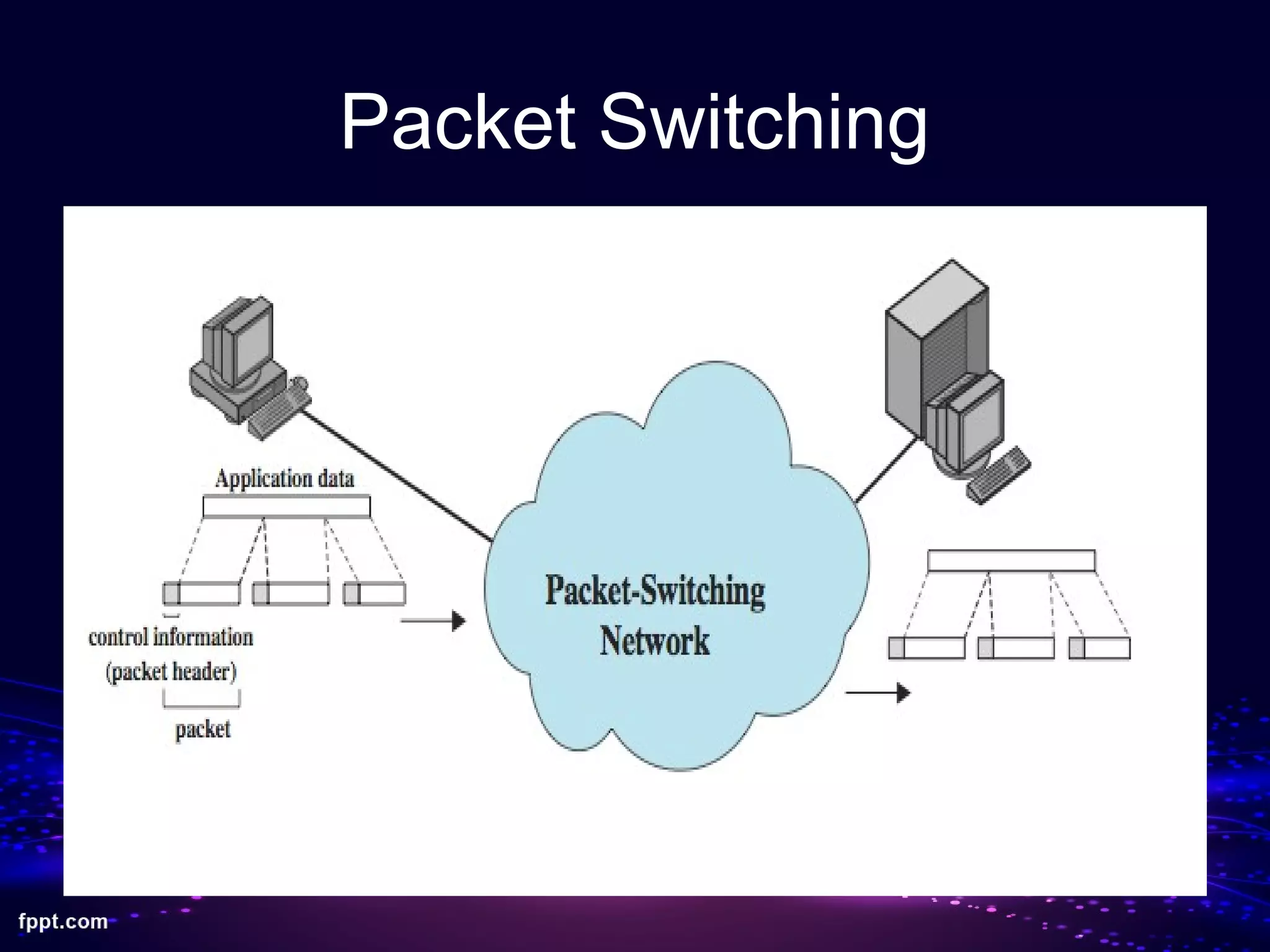
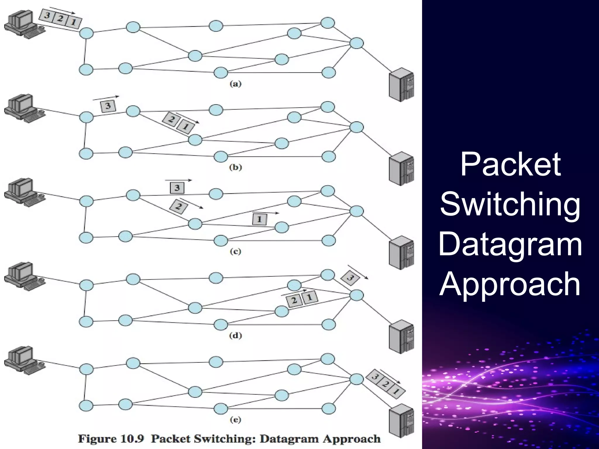
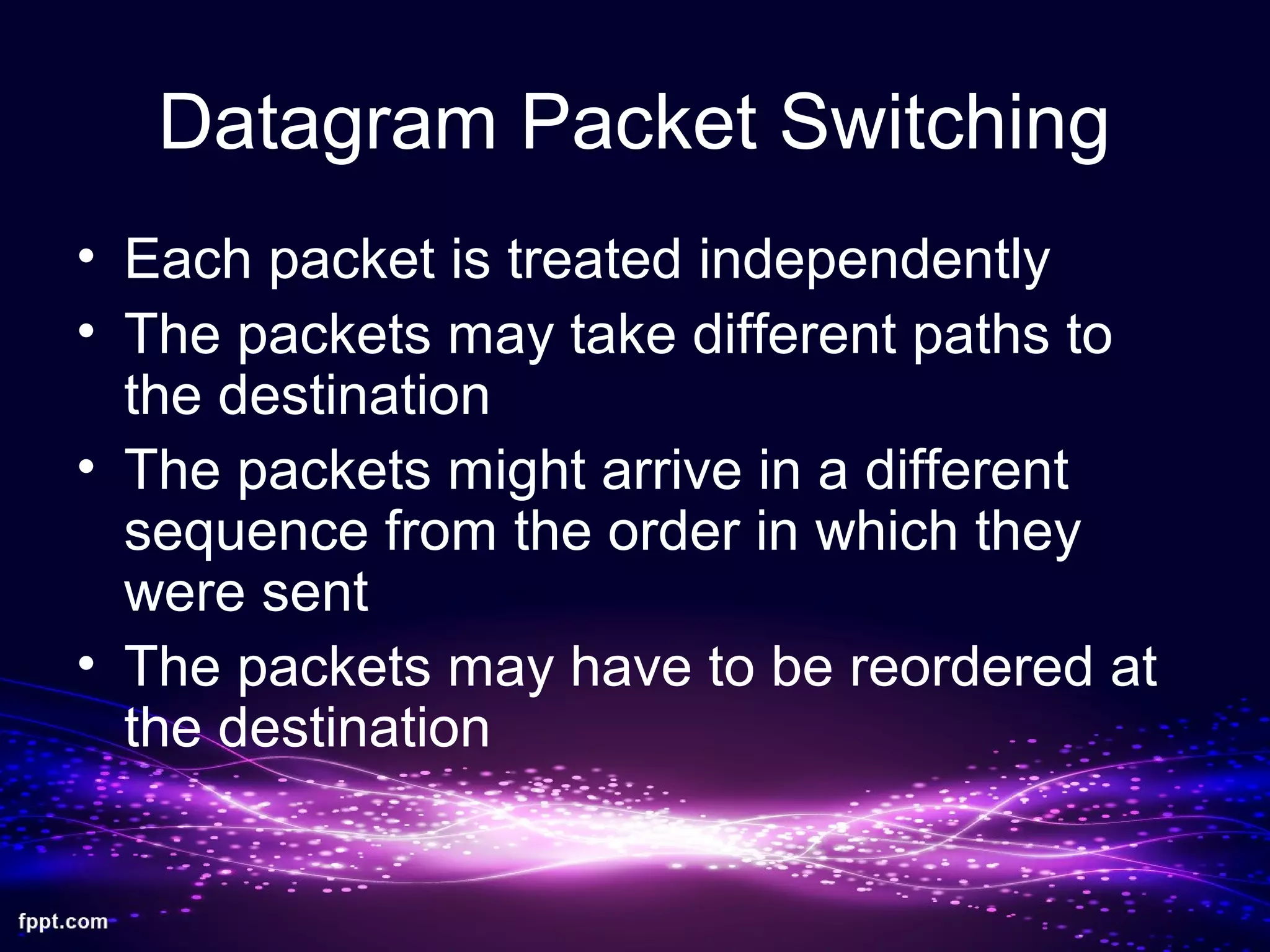
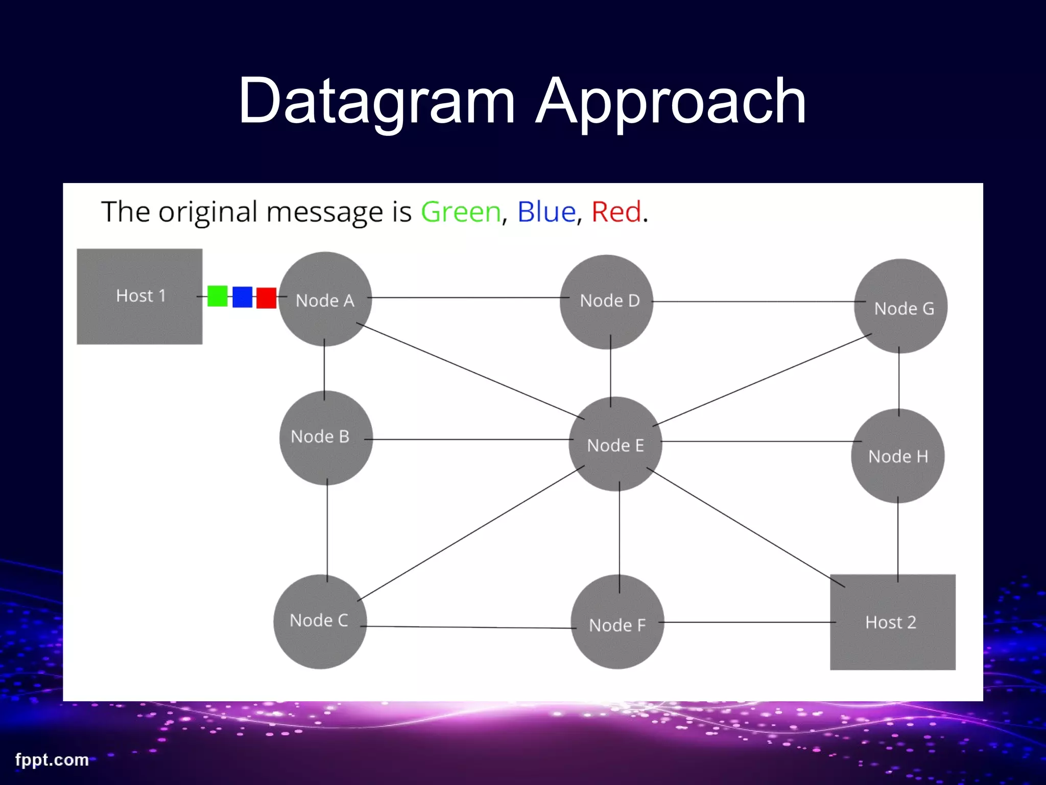
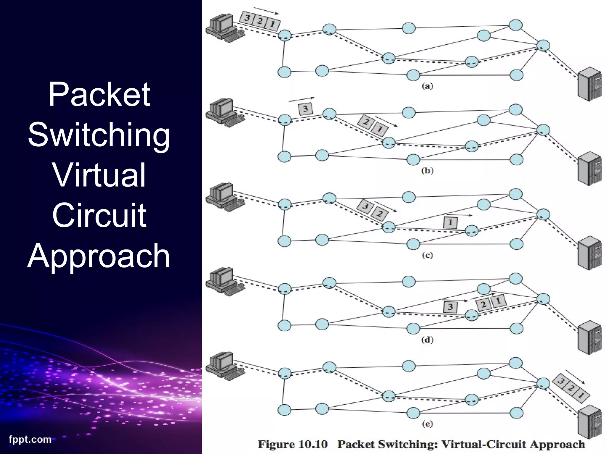
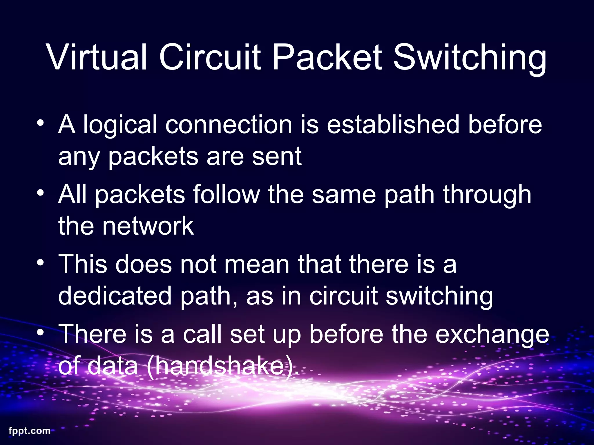
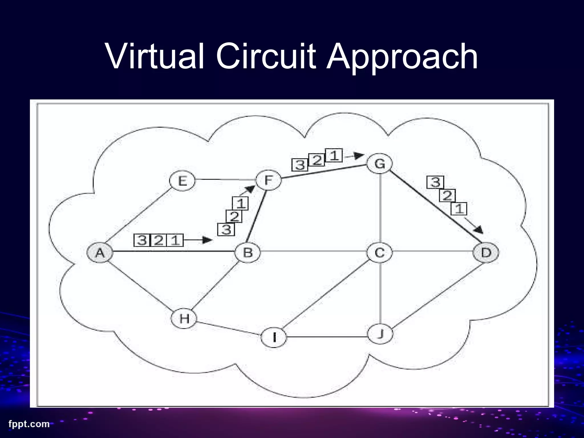
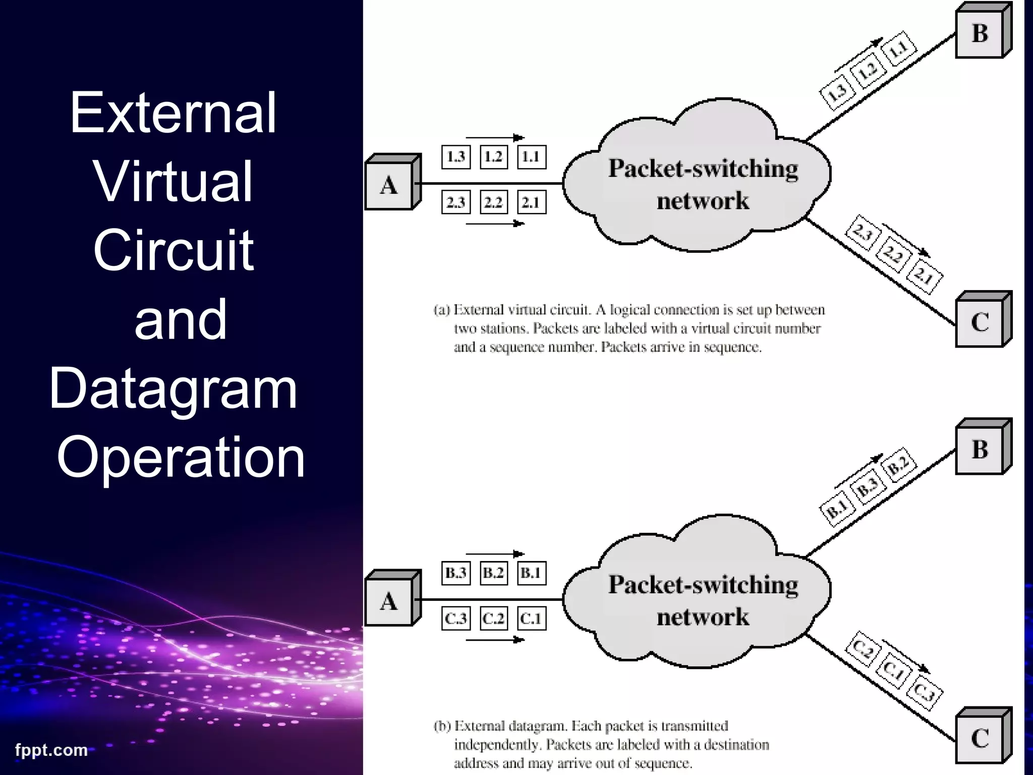
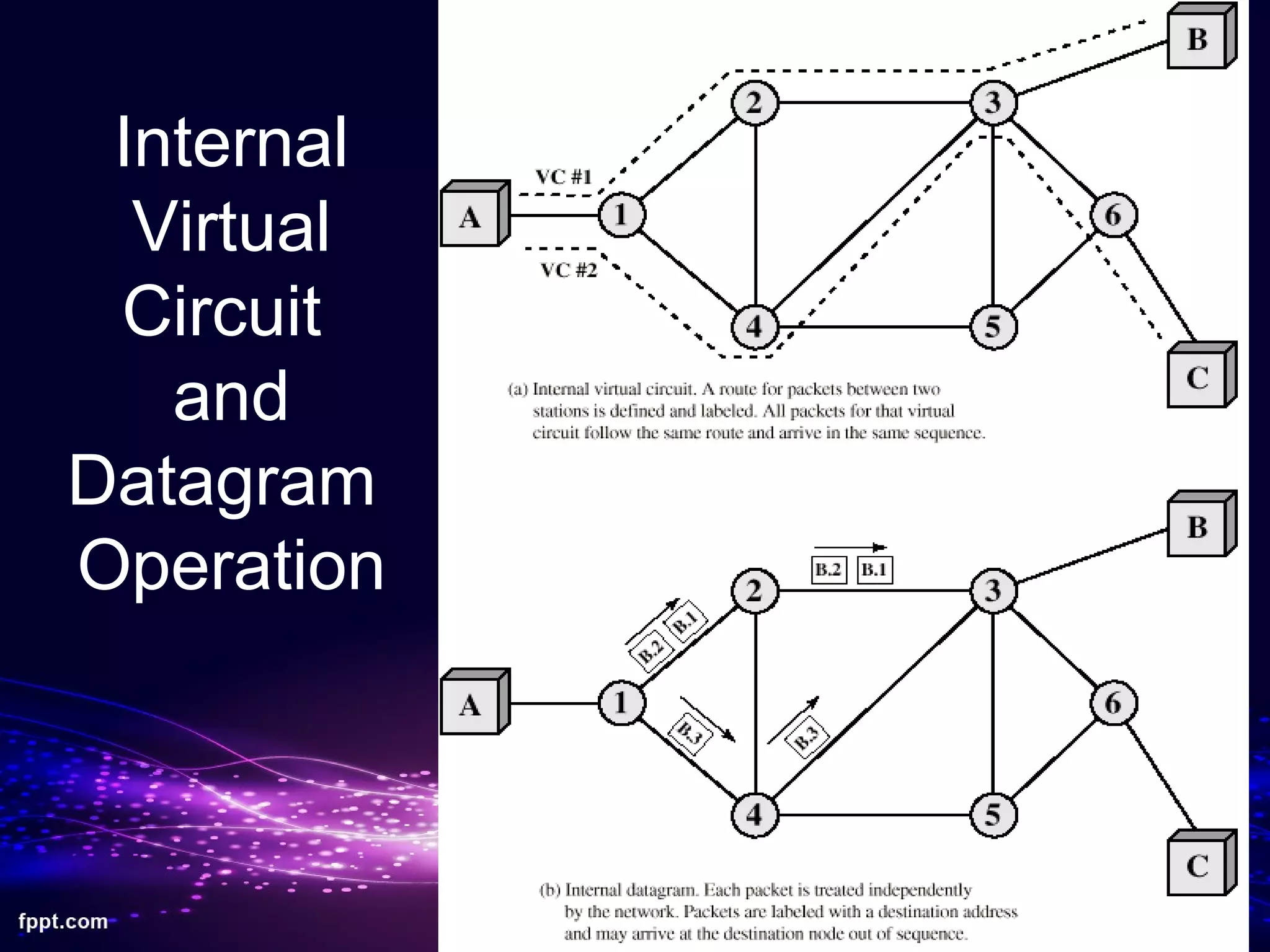
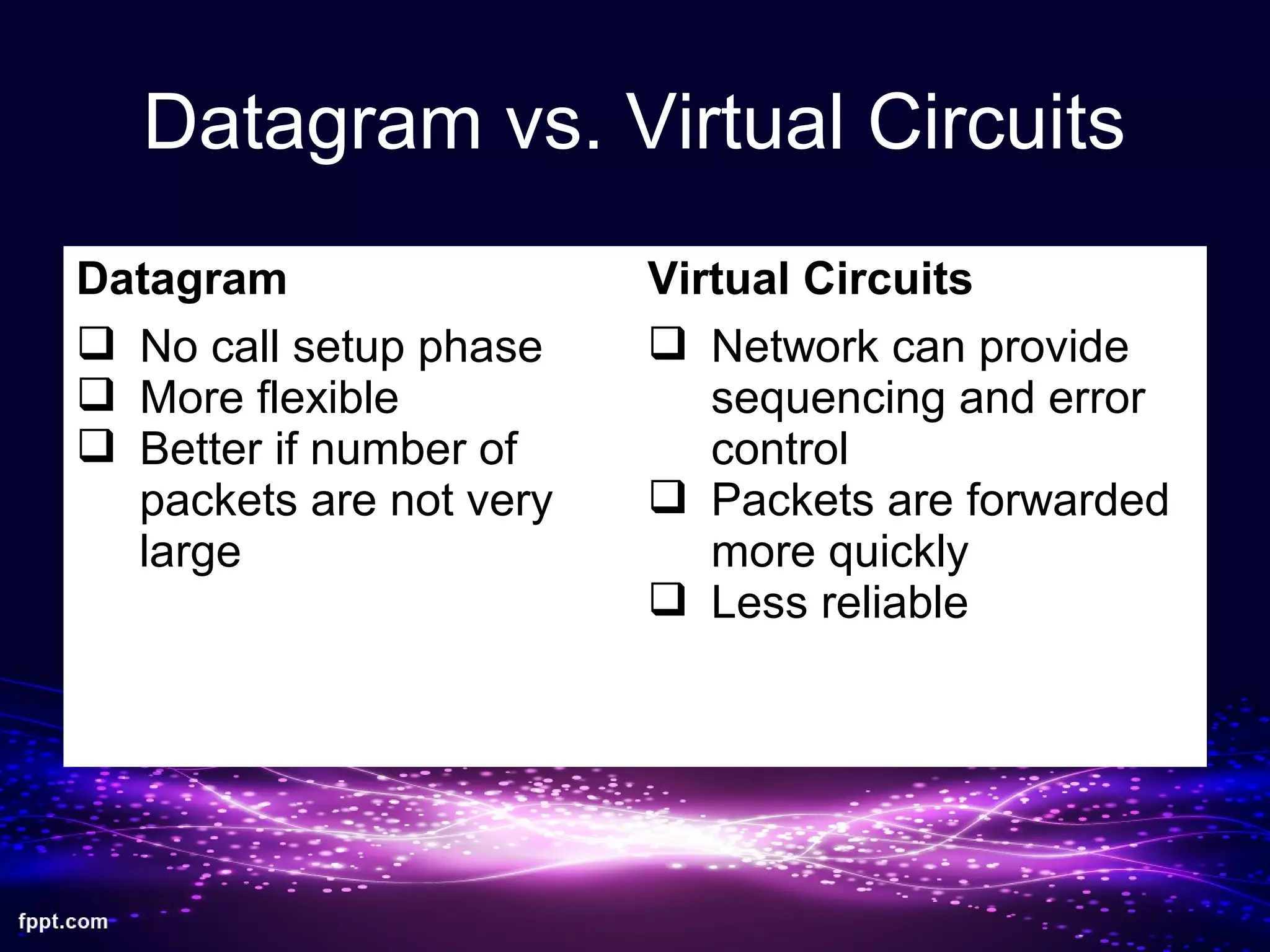
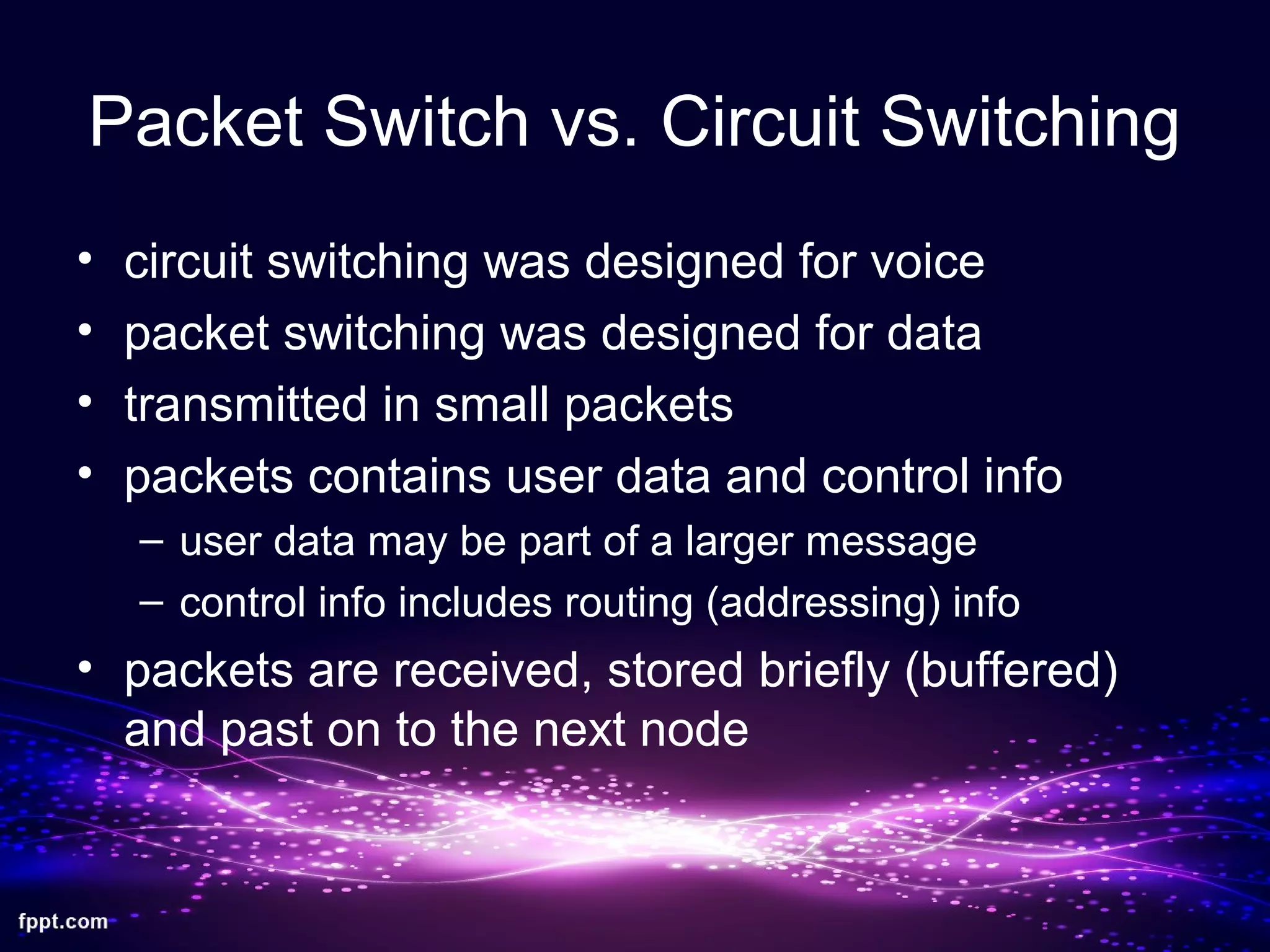
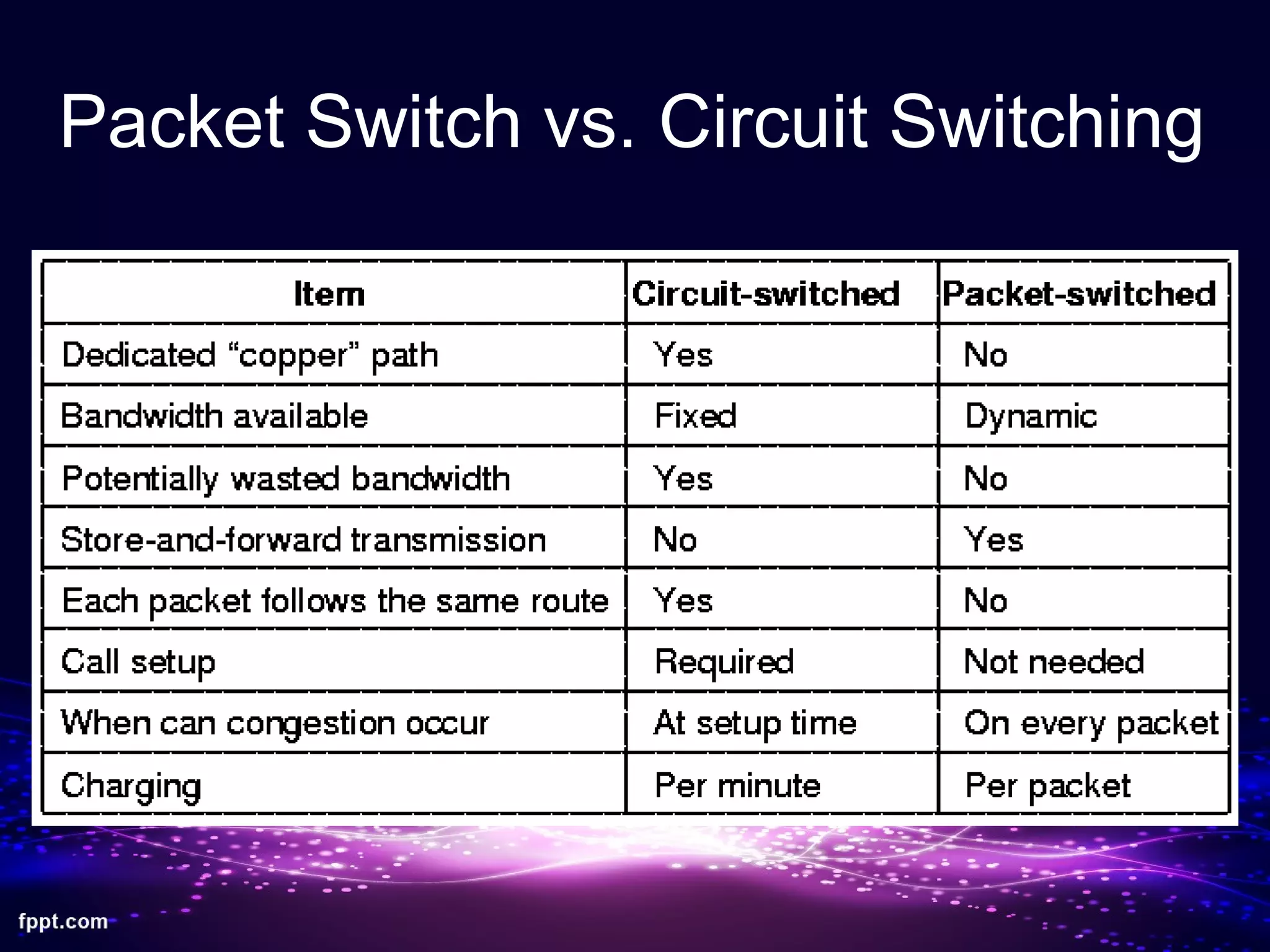
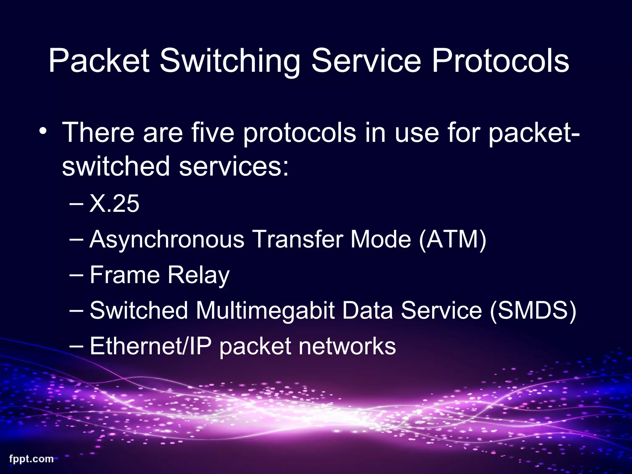
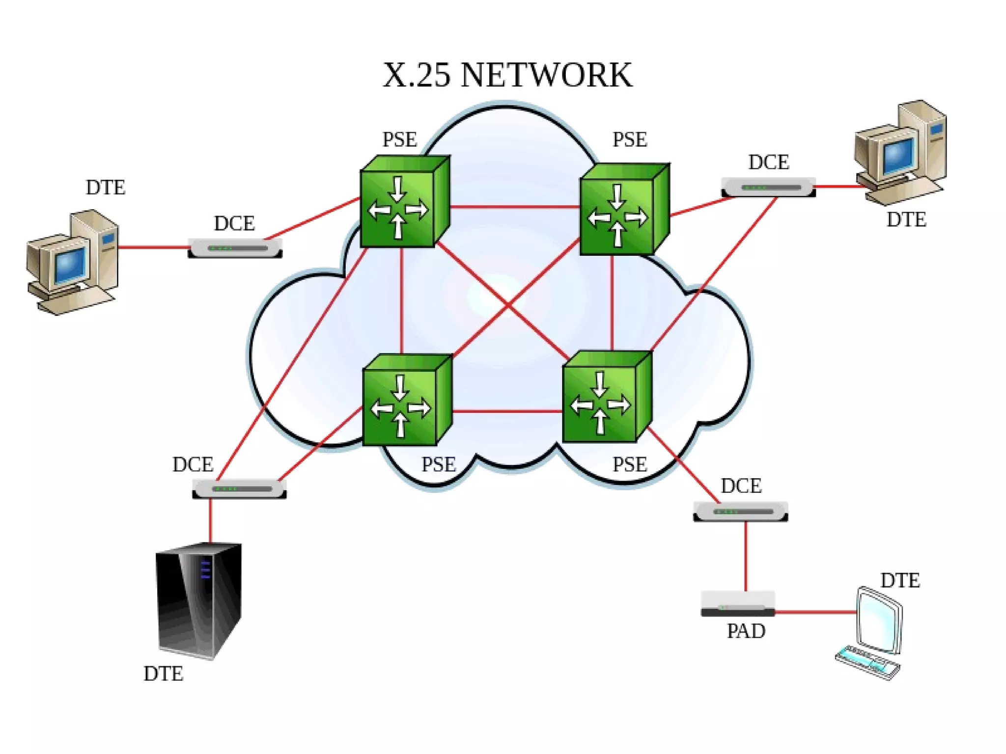
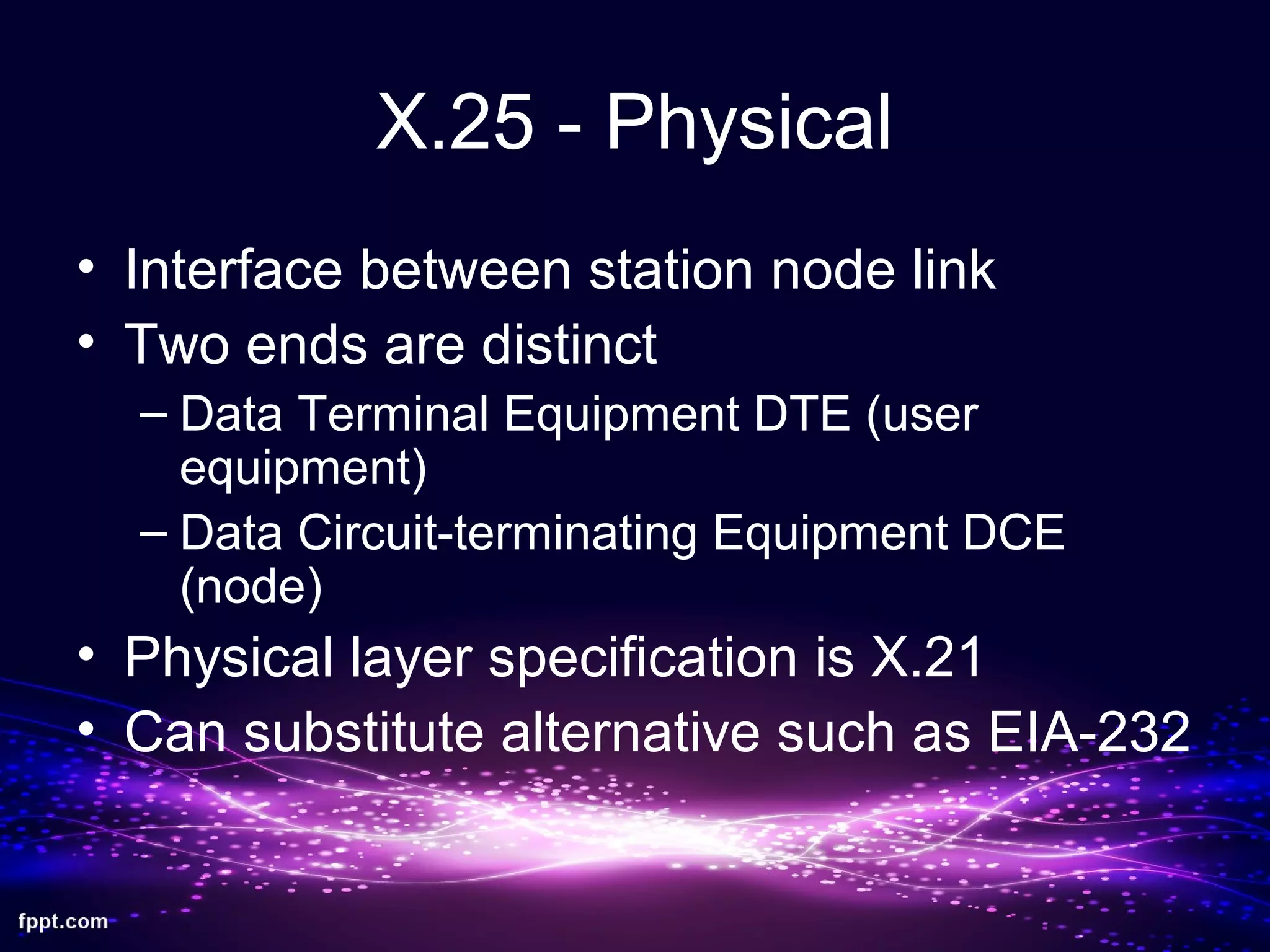
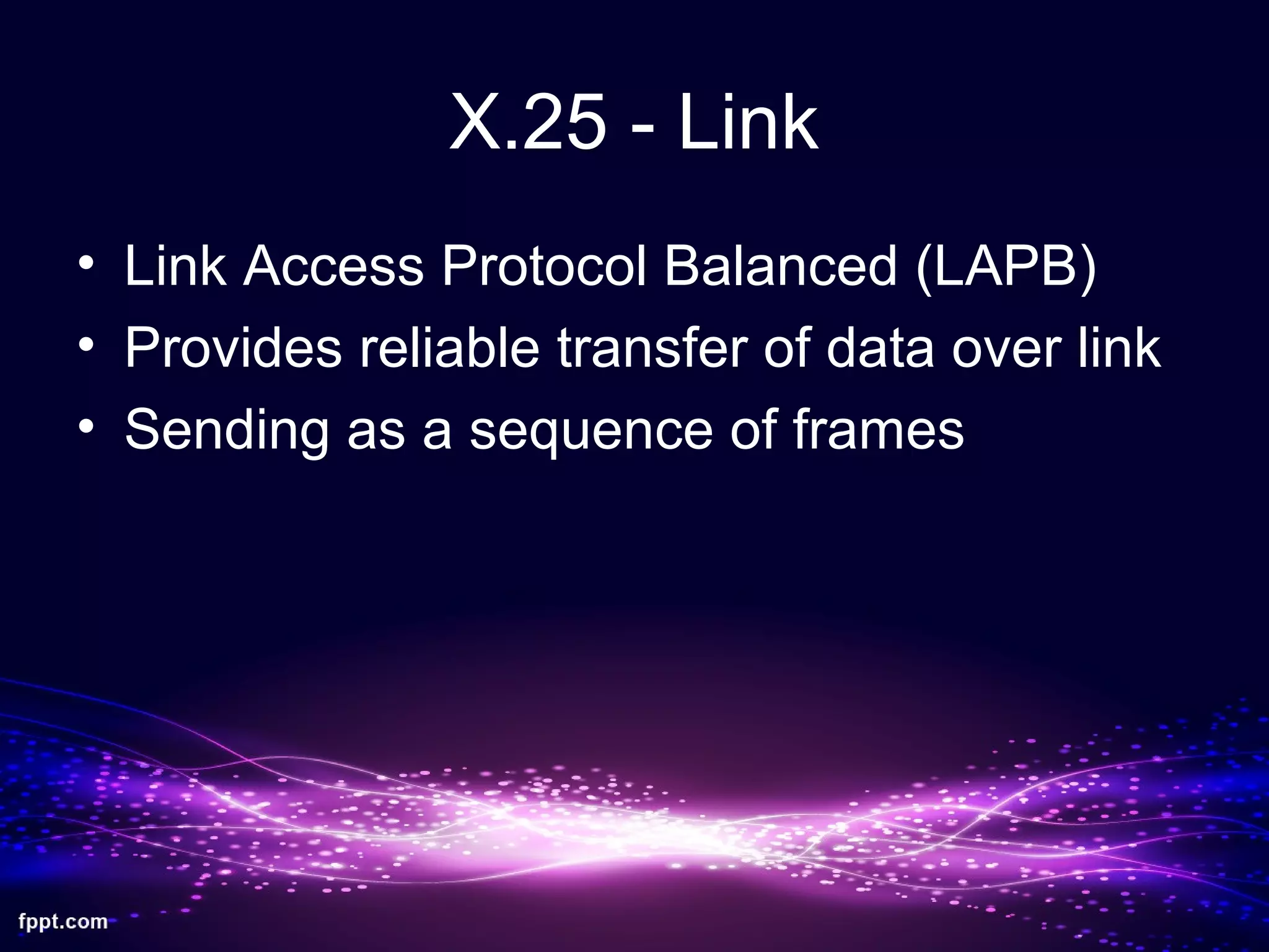
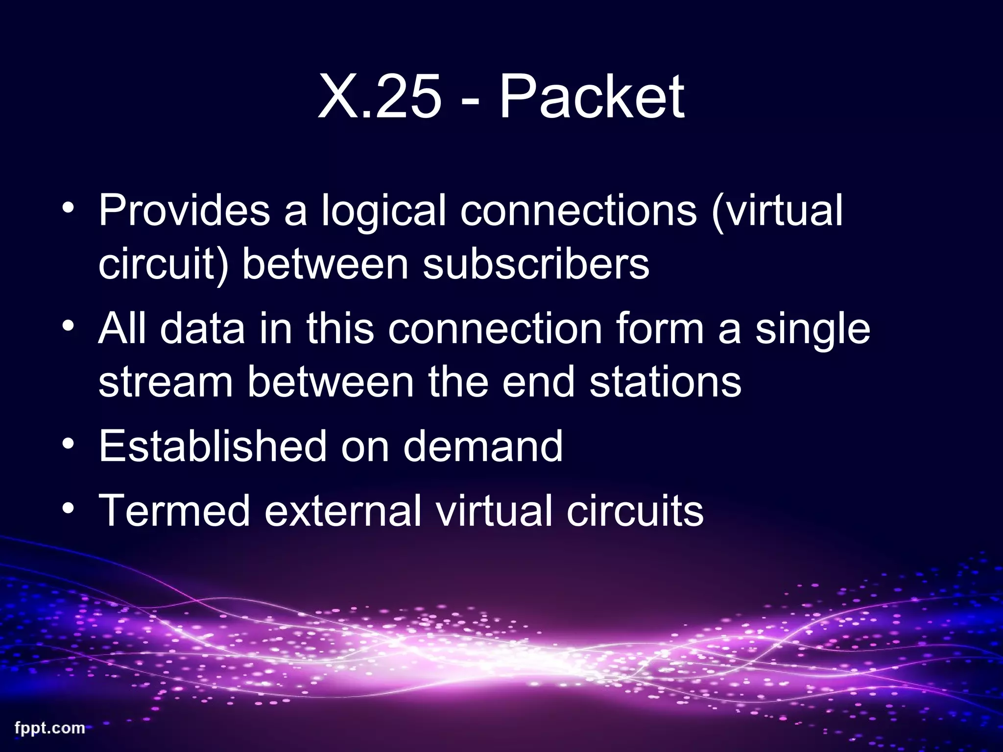
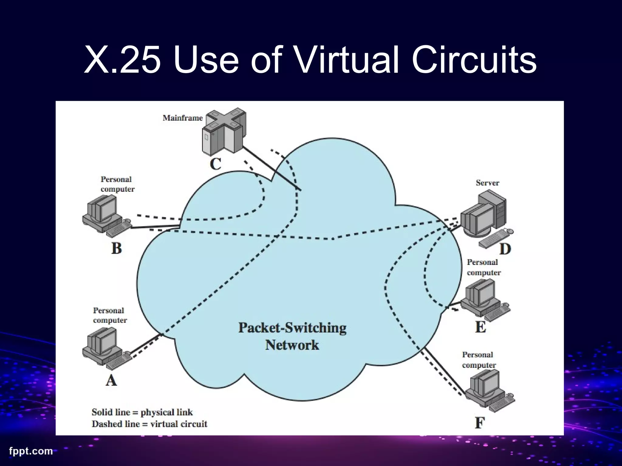
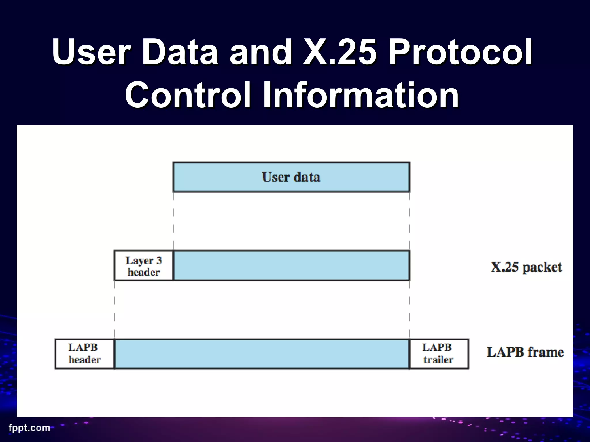

Packet switching involves dividing data into packets that are transmitted through a network independently and reassembled at the destination. The X.25 protocol, developed in the 1960s, was one of the first standards used for packet switching networks. It establishes virtual circuits between nodes to transmit packets reliably while providing billing based on connection time. While widely used historically, X.25 has limitations for modern high-speed networks due to its overhead and lower transmission speeds compared to newer protocols like ATM and Frame Relay.