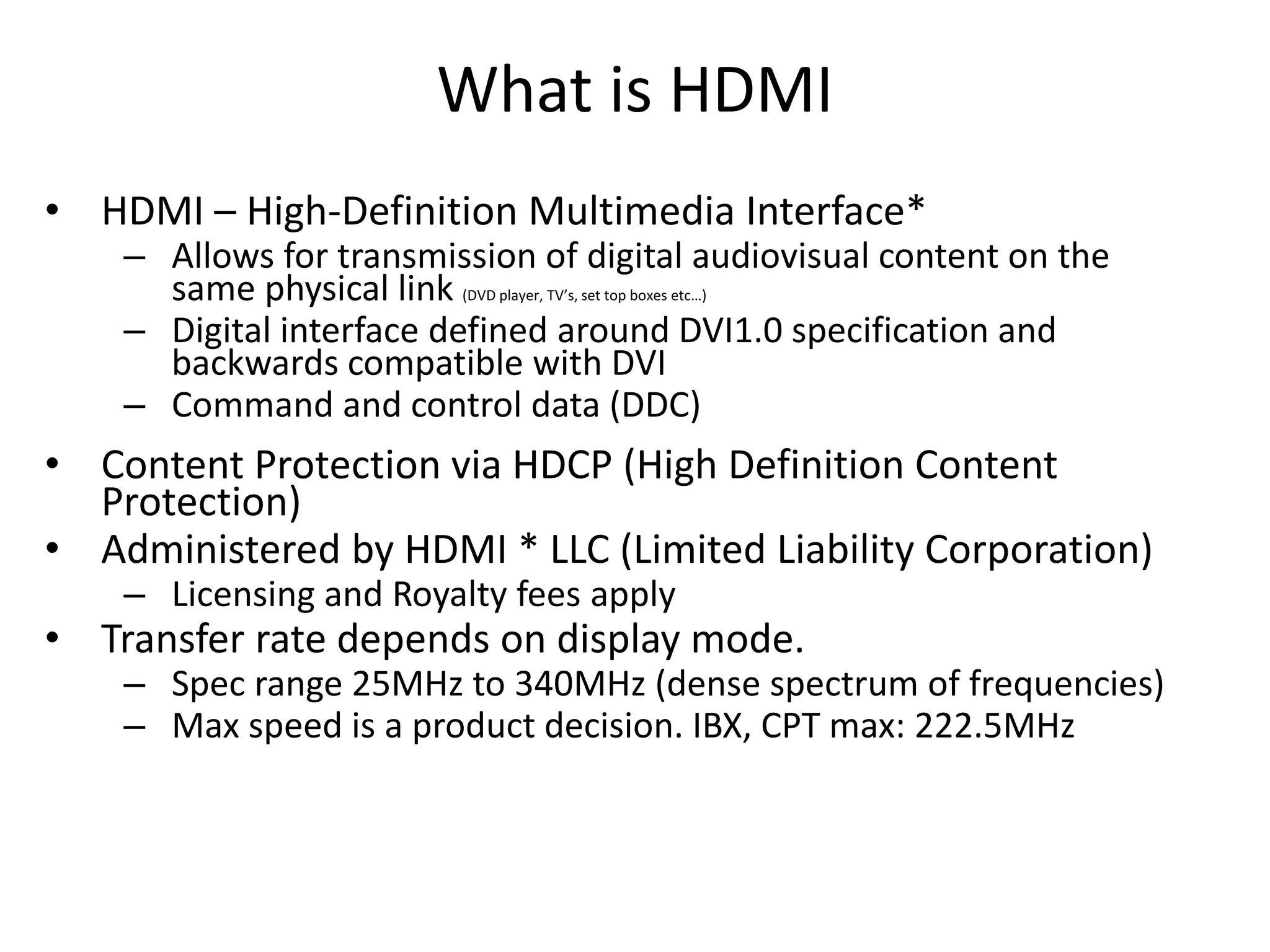
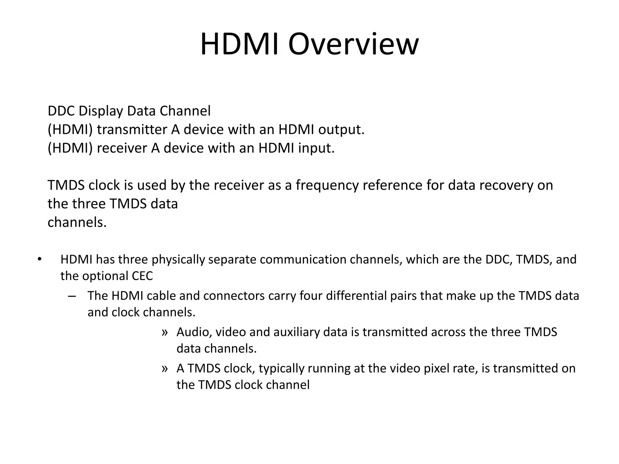
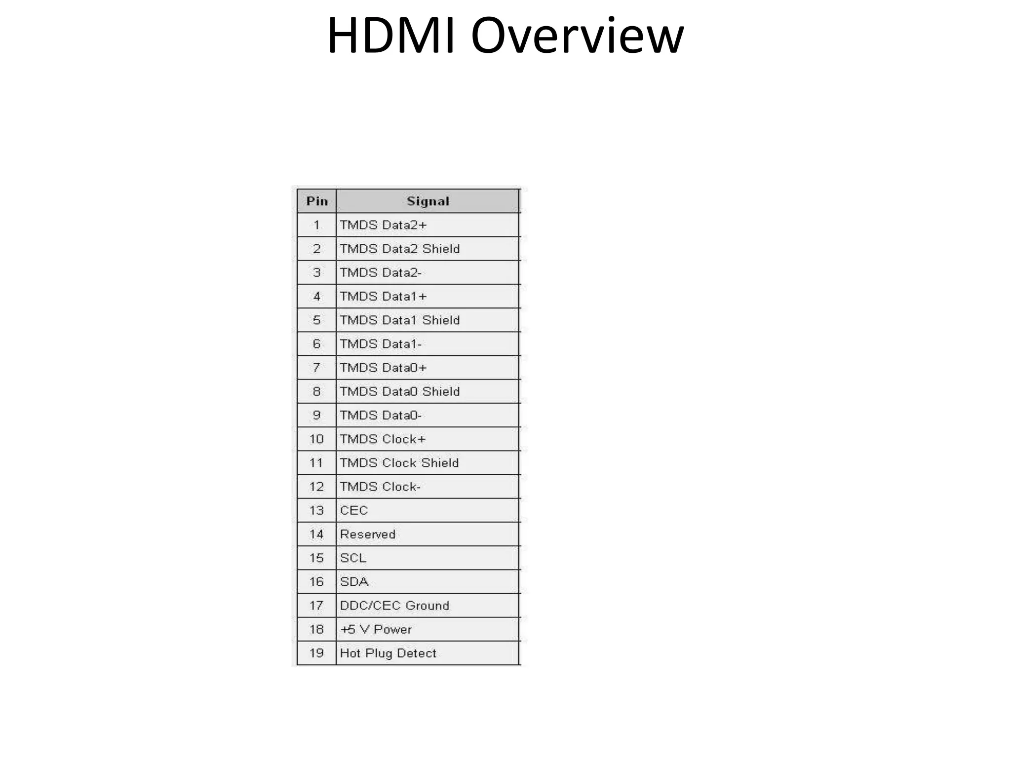
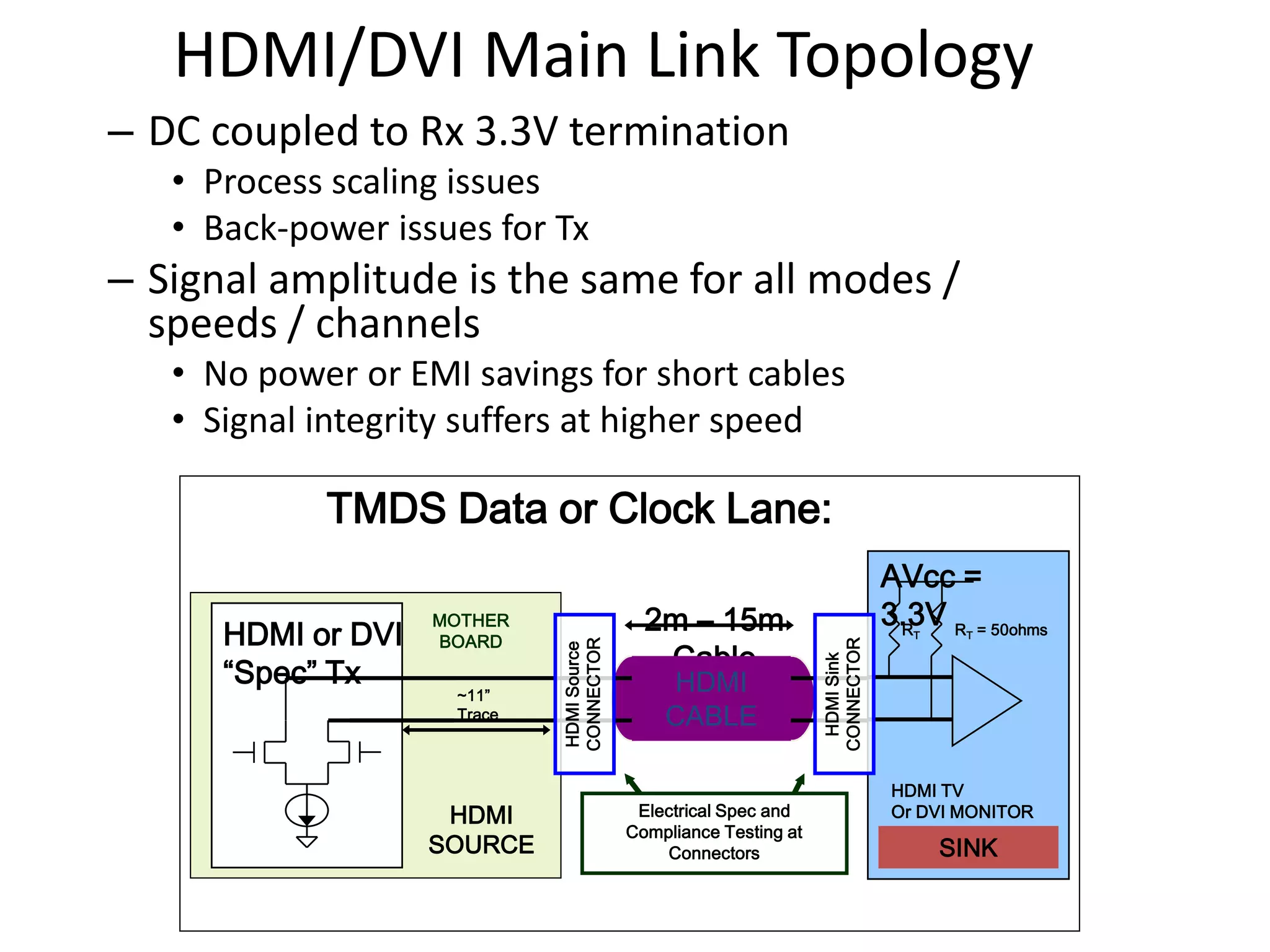
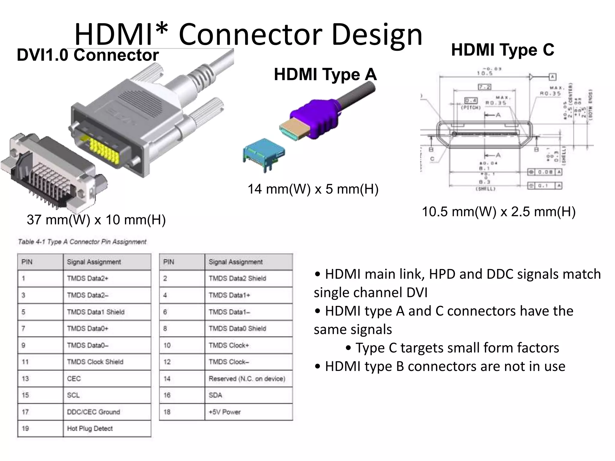
HDMI (High-Definition Multimedia Interface) facilitates the transmission of digital audio and video content through a single cable, with a compatibility foundation on the DVI specification. It includes various features such as content protection via HDCP, multiple data channels, and different connector types (A, B, C) to support various resolutions and applications. HDMI connects devices like DVD players and TVs, enabling high-quality audiovisual interactions while ensuring configuration and status exchange between devices.


![CETH for XDP [Linux Meetup Santa Clara | July 2016]](https://cdn.slidesharecdn.com/ss_thumbnails/ceth5overview1-160801192921-thumbnail.jpg?width=640&height=640&fit=bounds)