Downloaded 169 times
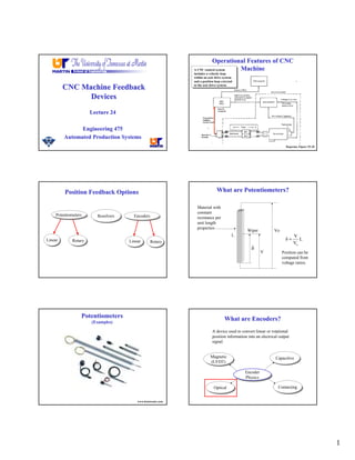
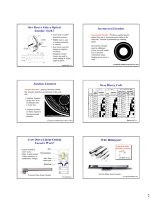
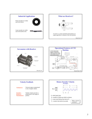
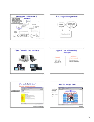
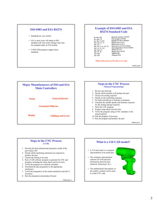
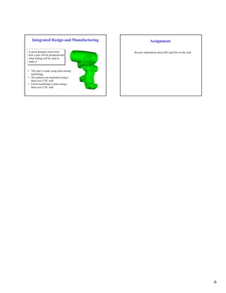

CNC machines use position feedback devices like encoders and potentiometers to provide information to the control system on the position of the machine axes. Encoders convert linear or rotational position into an electrical signal and come in various types like optical or magnetic. ISO and EIA standards define common programming languages used to operate CNC machines manually or through CAM software. Proper integration of CAD, CAM, and CNC programming is needed to efficiently manufacture parts.