Downloaded 134 times

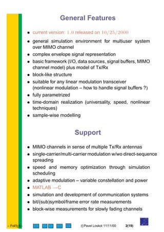
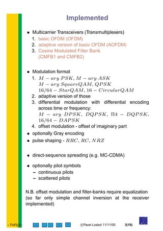
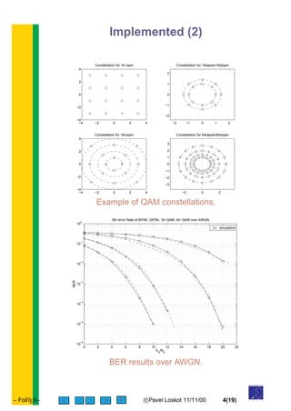
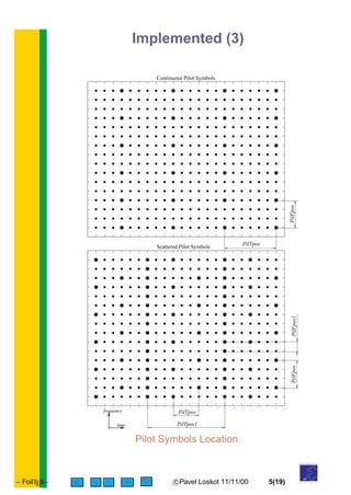
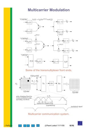
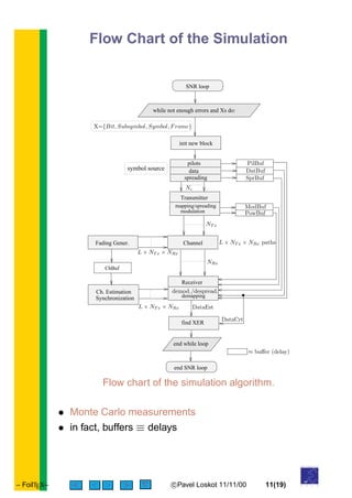
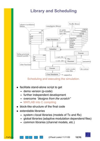
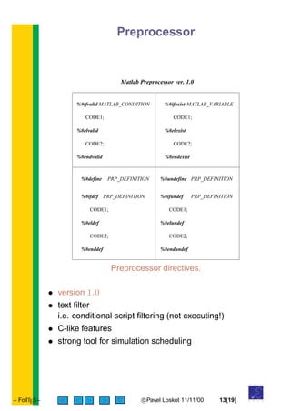
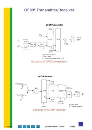

This document describes a MATLAB simulation environment for linear modulation communication systems, detailing its features, including multiuser system support over MIMO channels and various modulation formats. It elaborates on implemented technologies such as multicarrier transceivers, adaptive modulation, pulse shaping, and the simulation structure for performance measurements. Additionally, it outlines future directions for enhancing the preprocessor and expanding libraries for improved system development.


![RF Module Design - [Chapter 4] Transceiver Architecture](https://cdn.slidesharecdn.com/ss_thumbnails/rfch4-150613070346-lva1-app6891-thumbnail.jpg?width=640&height=640&fit=bounds)