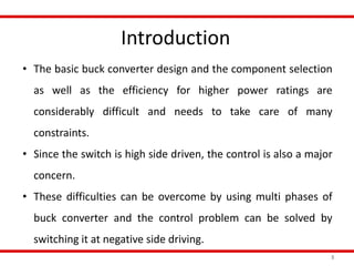
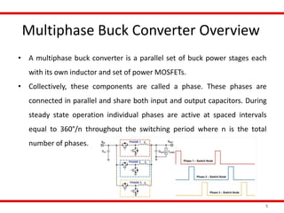
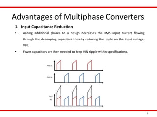
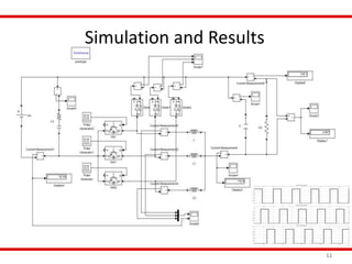
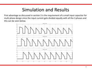
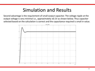
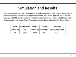
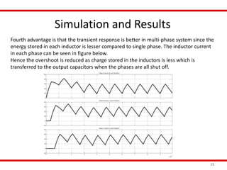
This document presents a technical seminar on a multi-phase buck converter with low side switching for high current applications. It discusses the advantages of multi-phase converters over single phase converters, including lower input and output capacitance requirements, improved thermal performance and efficiency, better transient response, and simpler low side switching. It then describes the design of a three phase buck converter, including specifications, component selection, and MATLAB simulation results demonstrating the advantages of the multi-phase design.
![References
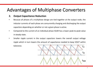
17
[1] Y. Ahn, I. Jeon and J. Roh, "A Multiphase Buck Converter With a Rotating Phase-Shedding Scheme
For Efficient Light-Load Control," in IEEE Journal of Solid-State Circuits, vol. 49, no. 11, pp. 2673-2683,
Nov. 2014.
[2] W. Huang and B. Lehman, "A Compact Coupled Inductor for Interleaved Multiphase DC–DC
Converters," in IEEE Transactions on Power Electronics, vol. 31, no. 10, pp. 6770-6775, Oct. 2016.
[3] N. Altin, S. Balci, S. Ozdemir and I. Sefa, "A comparison of single and three phase DC/DC converter
structures for battery charging," 2013 International Conference on Renewable Energy Research and
Applications (ICRERA), Madrid, 2013, pp. 1228-1233.
[4] Baba, David, “Benefits of a multiphase buck converter,” (SLYT449), Texas Instruments, 2012.
[5] Carmen Parisi, “Multiphase Buck Design From Start to Finish”, (SLVA882), Texas Instruments, 2017.](https://image.slidesharecdn.com/4thsemseminar-181006083805/85/Multi-phase-buck-converter-with-low-side-switching-for-high-current-application-17-320.jpg)


![[1_CV] Model Predictive Control Method for Modular Multilevel Converter Appli...](https://cdn.slidesharecdn.com/ss_thumbnails/1cvmodelpredictivecontrolmethodformodularmultilevelconverterapplications-190418082702-thumbnail.jpg?width=640&height=640&fit=bounds)