Download to read offline
![International Research Journal of Engineering and Technology (IRJET) e-ISSN: 2395-0056
Volume: 04 Issue: 10 | Oct -2017 www.irjet.net p-ISSN: 2395-0072
© 2017, IRJET | Impact Factor value: 6.171 | ISO 9001:2008 Certified Journal | Page 1014
Control of a Modular Multilevel DC/DC Converter for Regenerative
Applications
L. Rajesh Kumar
M.Tech. in power electronics, Dept. of EEE, RGMCET, Nandyal, A.P., India
---------------------------------------------------------------------***--------------------------------------------------------------------
Abstract - In this paper, different cascaded (buck, boost)and
multilevel topologies are compared for regenerative
applications to interface super capacitors as energy storage
device to dc bus. It shows modular multilevel dc/dc converter
(MMC) is best in front of cascaded converters in terms of
weight and volume reduction of inductance when phase
shifting modulation strategy is used. The proposed control
method can balance super capacitor voltage by using specific
output current. The converter topologies and control methods
are verified by simulation results.
Keywords: Modular multilevel dc/dc converetrs(MMCs),
supercapacitors(SCs), buck conveter,boost converter
phase shifting, control techniques.
1. INTRODUCTION
In response to the changing global backdrop, scientific
group of people and major countries are focusing only on the
energy requirements for their development. So, mainly
focused on the high energy storage devices which are not
present in present world. Hence, super capacitors represent
one of the recent innovations in the field of electrical energy
storage [1], and will find their position in many applications
like electric traction and hybrid electricvehicles(HEV)where
high power levels are needed during short period of time,
from milliseconds to some hundreds of seconds. Since, super
capacitors are used as energystorage devices in regenerative
braking applications to store braking energy of HEV [2].
This paper focuses in interfacing super capacitors to a dc
bus by cascaded and multilevel converters [3].Through
parallelization of batteries and SCs has many drawbacks that
there is no control of energy flowing to or from and the
voltages across the super capacitors are almost constant. To
achieve energy management capabilities, converters are
needed to control the energy flow in the SCs.
SCs are low voltage devices. So, to achieve high voltage
which is neededintractionapplicationslargenumbersofcells
have to be connected in series. But it leads voltage imbalance
across the SCs due to difference in capacitances of each super
capacitors.
To attain high voltage from low voltage devices, or vice
versa, cascaded and multilevel converters [4], [5] have been
employed in literature. Normally, modular multilevel dc/dc
converter (MMC) is used as a traction converter in HEV to
achieve charge balance in batteries.
The usage of MMC in traction applications has many
advantages which includes the fall of the voltage across the
inductor, splitting one inductance into several inductances.
Splitting the converter into a number of converters also
reduces the voltage rating of the transistors (IGBT’s). Low
voltage transistors (IGBT’s) can attain higher switching
frequencies and high current capability. One more important
advantage is modularity thatcanmakesimplersystemdesign
and cooling, andcan amplifyreliabilityinN+1surplussystem.
Self-regulating energy management can be achieved for
each of the low voltage sources and increases the output
frequency which reduces the inductive components size [6].
Multilevel converter topologies are the good swapping
solution between performance and cost, as control obscurity
increases compared to usual converters.
2. CASCADED AND MMCs
Two quadrant dc/dc converters is neededinregenerative
applications with SCs as energy storage devices. When
braking, energy flows from load to storage devices and in
traction mode, energy flows from energy storage devices to
load. All the dc/dc converters are presented in this paper are
based on the HB topology.
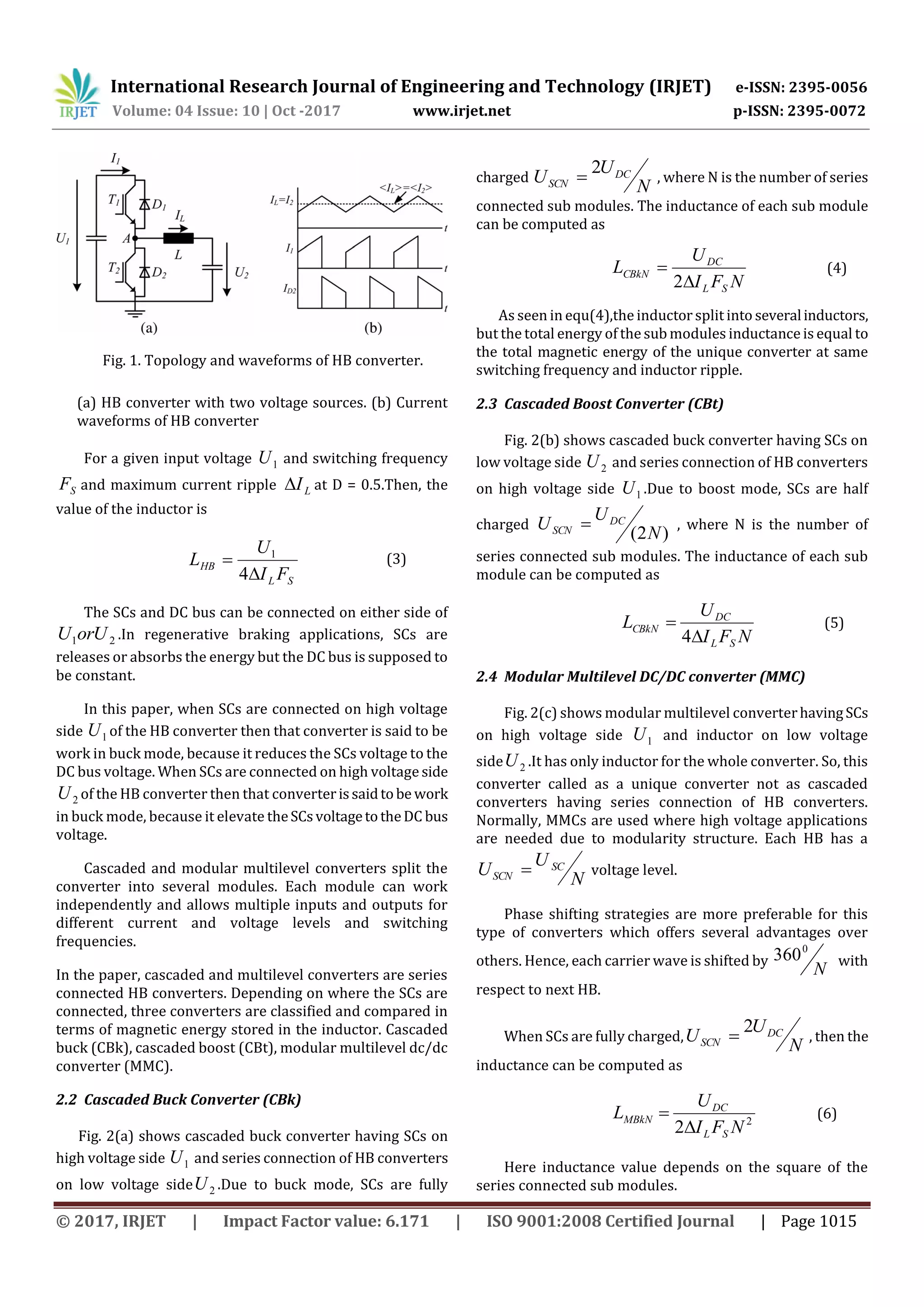
2.1 HB Converter
Fig. 1(a) shows the HB converter having two transistors
with anti-parallel diodes connected in series. This converter
has two voltages U1 and U2 connected on both sides with one
inductor. The HB converter is unidirectional in voltage but
bidirectional in current.
When converter working in continuousconductionmode,
the transfer function of the two voltages and currents are
12 .UDU (1)
21 .IDI (2)
‘D’ is the duty cycle and it is in range between 10 D
and I1, I2 are the two currents on both sides of the converter
where I2 =IL. But, the condition 21 UU must be always
satisfied.](https://image.slidesharecdn.com/irjet-v4i10181-171128093203/75/Control-of-a-Modular-Multilevel-DC-DC-Converter-for-Regenerative-Applications-1-2048.jpg)

![International Research Journal of Engineering and Technology (IRJET) e-ISSN: 2395-0056
Volume: 04 Issue: 10 | Oct -2017 www.irjet.net p-ISSN: 2395-0072
© 2017, IRJET | Impact Factor value: 6.171 | ISO 9001:2008 Certified Journal | Page 1020
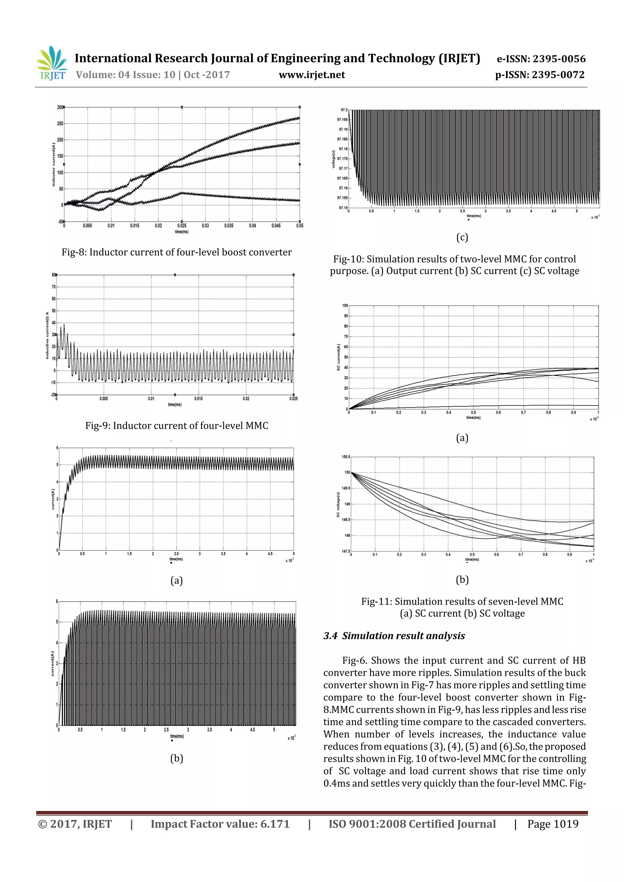
11 shows that seven level MMC has SC voltage and current
balancing.
3. CONCLUSION
The paper presents a modular multilevel dc/dc converter
(MMC) used in regenerative applications to interfaceenergy
storage devices to the DC bus. The main objective is to
reduce magnetic components size and volumewhichismost
suitable for electric hybrid vehicles(EHV)alongwithvoltage
balancing in SCs is accomplished.
REFERENCES
[1] A. Rufer and P. Barrade,“Asupercapacitor-basedenergy-
storage system for elevators with soft commutated
interface,” IEEE Trans. Ind. Appl., vol. 38, no. 5, pp. 1151–
1159, Sep.–Oct. 2002.
[2] P. Thounthong and S. Rael, “The benefits of
hybridization,” IEEE Ind. Electron. Mag., vol. 3, no. 3, pp. 25–
37, Sep. 2009.
[3] J. Dixon, S. Bosch, C. Castillo, and M. Mura, “Ultra
capacitors as unique energy storage for a city-car using five-
level converter,” in Proc. 35th Annu. Conf. IEEEInd.Electron.,
2009, pp. 3854–3859.
[4] F. Zhang, F. Z. Peng, and Z. Qian, “Study of the multilevel
converters in DC-DC applications,” in Proc. IEEE 35th Annu.
Power Electron. Spec.Conf.PESC2004,vol.2,pp.1702–1706.
[5] G. R. Walker and P. C. Sernia, “CascadedDC-DCconverter
connection of photovoltaic modules,” IEEE Trans. Power
Electron., vol. 19, no. 4, pp. 1130–1139, Jul. 2004.
[6] V. Vorperian, “Synthesis of medium voltage DC-to-DC
convertersfromlow-voltage, high-frequencyPWMswitching
converters,” IEEE Trans. Power Electron., vol. 22, no. 5, pp.
1619–1635, Sep. 2007.](https://image.slidesharecdn.com/irjet-v4i10181-171128093203/75/Control-of-a-Modular-Multilevel-DC-DC-Converter-for-Regenerative-Applications-7-2048.jpg)

This document describes and compares different converter topologies for interfacing supercapacitors to a DC bus, including for regenerative applications. It finds that a modular multilevel DC/DC converter (MMC) has advantages over cascaded buck and boost converters in terms of reduced weight and volume of inductance. When using phase shifting modulation, the MMC can balance supercapacitor voltages through control of the output current. Simulation results show the MMC achieves lower current ripples and faster response times compared to the other topologies. Control methods are presented to regulate the output current and balance the supercapacitor voltages in the MMC.


![[IJET V2I5P8] Authors: Lakshmi K R, Kavitha Issac, Kiran Boby](https://cdn.slidesharecdn.com/ss_thumbnails/ijet-v2i5p8-161107140749-thumbnail.jpg?width=640&height=640&fit=bounds)


![[1_CV] Model Predictive Control Method for Modular Multilevel Converter Appli...](https://cdn.slidesharecdn.com/ss_thumbnails/1cvmodelpredictivecontrolmethodformodularmultilevelconverterapplications-190418082702-thumbnail.jpg?width=640&height=640&fit=bounds)


