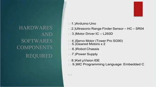
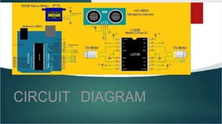
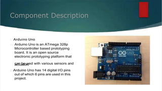
1) The document describes an obstacle avoiding robot project built using an Arduino Uno, ultrasonic sensor, motor driver IC, servo motor, geared motors, and chassis.
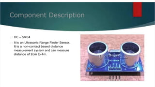
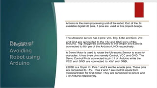
2) The robot is programmed to continuously measure the distance to obstacles using the ultrasonic sensor and avoid obstacles by rotating or backing up when distances are less than 15cm.
3) Potential applications of obstacle avoiding robots include household vacuuming, dangerous environments where human access is unsafe, and mobile robot navigation systems.