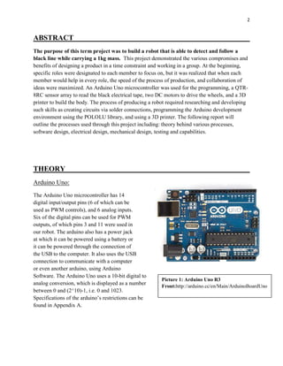
1
EPHY 1990 Introduction to Engineering Measurements
Team: 42Robotics
Group Members:
Kevin Arnold
Kael Kristjanson
Graeme MacAulay
Amitt Minhas
Due: April 10th
2015
2
ABSTRACT
The purpose of this term project was to build a robot that is able to detect and follow a
black line while carrying a 1kg mass. This project demonstrated the various compromises and
benefits of designing a product in a time constraint and working in a group. At the beginning,
specific roles were designated to each member to focus on, but it was realized that when each
member would help in every role, the speed of the process of production, and collaboration of
ideas were maximized. An Arduino Uno microcontroller was used for the programming, a QTR-
8RC sensor array to read the black electrical tape, two DC motors to drive the wheels, and a 3D
printer to build the body. The process of producing a robot required researching and developing
such skills as creating circuits via solder connections, programming the Arduino development
environment using the POLOLU library, and using a 3D printer. The following report will
outline the processes used through this project including: theory behind various processes,
software design, electrical design, mechanical design, testing and capabilities.
THEORY
Arduino Uno:
The Arduino Uno microcontroller has 14
digital input/output pins (6 of which can be
used as PWM controls), and 6 analog inputs.
Six of the digital pins can be used for PWM
outputs, of which pins 3 and 11 were used in
our robot. The arduino also has a power jack
at which it can be powered using a battery or
it can be powered through the connection of
the USB to the computer. It also uses the USB
connection to communicate with a computer
or even another arduino, using Arduino
Software. The Arduino Uno uses a 10-bit digital to
analog conversion, which is displayed as a number
between 0 and (2^10)-1, i.e. 0 and 1023.
Specifications of the arduino’s restrictions can be
found in Appendix A.
Picture 1: Arduino Uno R3
Front:http://arduino.cc/en/Main/ArduinoBoardUno
3
Picture 3: Motor
shield:http://arduino.cc/en/Main/ArduinoMotorShiel
dR3
Pololu QTR-8RC Sensor Array:
For this project we used the Pololu QTR-8RC
Sensor Array to read the black line that our
robot is programmed to follow. For this sensor,
no analog to digital converter was required. All
the outputs of the sensor are independent;
however, the LEDs are arranged in pairs in order to halve the current consumption. The LEDs are
controlled by a MOSFET (a type of transistor used for amplifying or switching electronic signals.)
After initially using all 8 sensors, we decided to not use the two outside sensors as we believed it
may add some logic to the robot and help the robot to not make the mistake of going onto the false
track that we set up into our trial circuit. However, after further testing we went back to using all 8
sensors to improve the robots ability to maneuver around acute corners. A program was employed
that if in the event that the robot were to miss an acute turn the robot would turn to the side where the
end sensor made a reading last. The specifications for the sensory array can be found in Appendix A.
Motor Shield:
Overview:
The motor shield is designed to drive inductive loads,
such as the 2 DC motors that are being used. It allows
the user to control the speed and direction of each
motor independently. This aspect will provide our
robot to make sharp corners easily by having one
wheel turn forward and the other in reverse without the
need for complex programming. It uses two separate
channels, A and B, which each use 4 pins each from
the Arduino. The four pins used each have their own
functions which are: direction, PWM, Brake, and Current Sensing. For our project we did not use
the brake or current sensing pins.
Power Supply:
The recommended input voltage for the motor shield is between 7-12 volts; however, a second
option was to cut the 𝑉𝑖𝑛 connection to run more than 9V. The latter option was chosen, and the
motors were run with an 18V power source, see Appendix A for the circuit. The 𝑉𝑖𝑛 connects the
power line from the shield to the Arduino. By disconnecting this connection it allows a separate
power supply to power the Arduino and Motor Shield separately, providing more power to the
motors.
Picture 2: Pololu ATR-8RC Sensor Array
4
Motor Connections:
To power the two DC motors connect the two wires from the motor to the (+) and (-) terminals
for the channels A and B. By doing this it allows you to control the direction of each motor by
using HIGH and LOW settings, and can control the varying speed of each motor by changing the
duty cycle values for the PWM control.
PWM (Pulse Width Modulation)
Because our robot uses a DC power supply, PWM was chosen to control the speed of each
motor. PWM, or pulse width modulation, is a means of controlling the average power supplied
to a given load, depending on sensor readings. Since the absolute potential the battery must be
either 0V or 18V, the system works through controlling the frequency at which the potential is
established. Our program designates the frequency of modulation through the
code: analogwrite(LPWM,LeftSpeed) with similar code for right motor. LPWM designates the
pin controlling the left motor. The function LeftSpeed is designated as a number between 0 and
255 and serves as the variable controlling the Frequency of modulation. This value is converted
as 18V*(LeftSpeed/255). As can be seen, in the case of LeftSpeed = 255, an average potential of
18V will be established; whereas in the case of LeftSpeed = 0, an average potential of 0V will be
established.
PID (Proportional, Integral, Derivative) Control
PID control is a loop structure feedback system that is used to reach a certain set point. This
system implements 3 separate control functions: derivative, integral, and proportional.
𝑊 = 𝑘 𝑝( 𝑇𝑠 − 𝑇 𝑂) + 𝑘 𝑑
𝑑(𝑇𝑠 − 𝑇 𝑂)
𝑑𝑡
+ 𝑘𝑖 ∫(𝑇𝑠 − 𝑇 𝑂) 𝑑𝑡
P: Proportional control is based on the difference between the set point and the value at the given
instant being considered. This is the simplest and most fundamental control of the three;
however, this may cause an overshoot, which in turn causes an oscillation of the set point if the
proportionality constant Kp is too large. Alternatively, if the Kp constant is too small, the set
point will not be able to be reached efficiently.
D: Derivative control is often referred to as the damping function. This function determines
difference between the set point and the value read at any instant. Using this difference, the
proportionality constant Kd adjusts the rate at which the given value approaches the set point
value; (i.e. the rate of change of the given point will increase with the distance between that and
the set point). Although this system reduces oscillations about the set point effectively, it may be
found that the set point is unable to be reached on account of being overly damped.
5
I: Integral control computes a cumulative sum of the error between the set point and the value at
any given instant. Although this control term was found to be ineffective, (and even
problematic), for our purposes, it can be used
to counteract the difference between the set
point and the maximum value that the
derivative control allows it to reach.
3D Printing Process:
The 3-D printer used for the body of our
robot is the LulzBot TAZ 4, which is a high
performance industrial printer. It uses free
software and an open source hardware which
allows for versatility. Our group initially
created a prototype base made from metal.
Using the printer for construction, the body
was designed on AUTOCAD. This
schematic uploaded initialized the printer
to produce a sequence to build the body. When uploading the body design the printer, several
problems presented themselves such as the design required on average 16 hours to produce.
Having this long of a printing time it allowed for lots of room for error. The foremost of this
possibility for error is the cooling rate of different layers of the design. Moreover, the initial
layer may be peeled off of the printer base if the cooling time is not ideal. Despite this, the
chassis produced for our robot was printed fairly well, with only cosmetic problems. When the
outer shell for the robot was left over night the print, the head of the printer jammed and was
unable to finish this portion of the design. Despite this inconvenience, the robot was still able to
perform the tasks required, as the walls and shell were mostly cosmetic. The printer settings can
be found in Appendix A.
DESIGN CHOICES
Mechanical:
Motors:
For our robot, two Gear Motor 8 - 143:1 Offset Shaft DC motors were provided. Originally the
motors were running off of one 9V battery each, but after some testing it was decided it would be
optimal to run each motor off of two 9V batteries connected in series to all for more power
delivered to the motors and overall more speed for the robot.
 143:1 gear reduction ratio
 7mm output shaft with double-flat outputs
Picture 4: LulzBot TAZ 4
https://www.lulzbot.com/products/lulzbot-taz-5-3d-printer
6
 Secondary output shaft (D) for encoders (not meant for rotational loads)
 Built-in safety ratchet clutch set for 60 in*oz. torque (easily modified for full "locked-up"
operation)
 Built in mounting holes
 53.8x48x47.8x22.9mm (2.12x1.88x0.902")
 31.5 grams (1.13oz)
 3-6VDC nominal operation
Wheels:
In accordance with the motor kit that was ordered, two wheels with molded on tires of r=3.5mm
were used. The friction created between the rubber of each of these tires and the ground causes
the locomotion of the vehicle. Because these wheels alone would lead to an unstable body, two
ball bearings were attached to the anterior end of the vehicle. Ball bearings were chosen because
they have a free rotation and will only serve a normal force to ensure stability. The wheelbase
was chosen to be 12.5cm, whereas the wheelbase of our prototype was 19cm. Although an
extended wheelbase will cause blunt turns and a short wheelbase will cause sharp turns, it was
found through trial and error that between the ranges of about 8-25cm, proportional values could
be found to successfully navigate a course.
Software:
The software has been developed using the Arduino development environment, using the QTR-
Sensor library to simplify reading the line. The program functions by first calibrating the sensors
in the "void setup()" section. After calibrating the sensors, the program will run "void loop()"
that runs the four sub programs "read_sensor_values(), special_cases(), calculate_pid(),
motor_control()" in a loop. In order to accomplish all the goals several programs have been
designed to complete each tasks. . They are based around this general outline:
Setup:
This program sets the pins on the Arduino as either an input or an output. It then begins to
calibrate the sensors using the function "qtrrc.calibrate()" while simultaneously telling the motors
to oscillate left and right, passing the sensor over the line during the calibration phase. It then
enables serial communications so data can be sent to the computer for analysis.
Read Sensor Values:
This program takes a reading of all sensors as a value between 0-1000, as well as to calculate an
estimate of where the line is as a number between 0-7000 where 3500 would be the center of the
line. If connected to a pc it will print these numbers in the serial monitor for analysis.
7
Special Cases:
This program checks for special cases where the estimated line position is incorrect. We have
used two methods for detecting these cases. In one method we compare the current position with
the last one measured; this is useful for navigating a broken track. The other method uses
individual sensor readings and looks for certain patterns; this is useful for detecting an upcoming
acute corner or a possible false line on the side. If a special case is detected it will either change
the error value generated, or in some cases it will override the PID control and make the motors
execute a manoeuvre.
Calculate PID:
This program uses the error value to calculate the PID value which will be used to determine the
motor speed. The integral term was removed from the equation because it presented too many
problems for the application we are using it for.
Motor Control:
This program controls the speed and direction of the motors. The motor speed is calculated by
either adding or subtracting the PID value from the base speed. The speed variable is written as
an absolute value as a PWM signal to the motor speed pins. If the speed variable is negative, the
digital signal going to the direction pins will alternate.
Electrical:
The first made about electrical design was to either build a motor shield or purchase one (see
Appendix A, picture 7 for electrical assembly with sensor). It was decided to purchase our motor
shield and the main reasons were the following:
1. Reliability; it is a tested produced made specifically for our Arduino.
2. Programming for the robot easier; it has forward and reverse functions build directly into
it.
3. Circuit design was made easier since the motor shield is connected directly on top of the
Arduino.
Having the motor shield also allows for more voltage to be sent to the motors which will increase
the speed of our robot and provide more power. For this reason, the next decision made was to
produce an 18 volt battery by using four 9 volt batteries (see Appendix A, picture 5 for electrical
assembly). To do this, the 𝑉𝑖𝑛 power line was cut from the motor shield to the Arduino so the
Arduino can be powered with a separate power supply. Using a switch and a 9 volt battery in
8
series connected to the Arduino, repetitive testing was made less tedious as the Arduino is able to
be turned on and off for testing (see Appendix A, picture 6 for electrical assembly). The
advantages to having a larger power supply are the following:
1. Provides torque to the wheels from the motor for the pulling section of the final testing
process.
2. Provides more speed for the drag race section of the final testing.
3. Was originally planning to use the full speed for the regular circuit, but during testing it
reduced our accuracy of following the line. Due to this we were reduced the speed by
50% inside the program.
TESTING AND CAPABLILTIES
Prototype Testing:
The initial design of our robot was crude; with
both the wheelbase and sensor placement
arbitrarily chosen (within reason). The sensor was
attached to the frame using only a piece of double
sided tape. This was varied the optimal distance
was found. Likewise, the wheel base was cut
down from either side using tin-snips until the
optimal length was found.
Initially determining kp, kd, why ki is not
included (I variable stacks and can become
uncontrollable). We started with just the
proportional constant. To determine a good place
to start testing values we used a value such that
𝐾𝑝 ∙ (3500 − 𝐸𝑟𝑟𝑜𝑟 𝑚𝑎𝑥) = 2 ∙ 𝑆𝑝𝑒𝑒𝑑 𝑚𝑎𝑥
Wheel Base:
Sensor Placement:
A lot of testing was gone into the placement of our sensor and how far its distance should be
from the wheel base. In our first prototype of our robot body we had our senor placed
approximately 12cm from the wheel base which seemed to work fine at the speed we were
running at. However, after changing our body to a more compact design, we moved the sensor
up to about 5 cm. We then added more batteries to our design, increasing the amount of power
outputted by the motors and overall increases the speed of the robot. After some research we
Picture 5: Prototype Design
9
observed that the faster robots had their sensors placed farther away from the wheel base to allow
for faster readings and the wheels to adjust more quickly. Although, after testing the robot after
moving the sensor further away, we noticed that the robot was no longer able to make sharper
turns because the sensor was reading too far ahead. In the end we went back to our previous
design and placed the sensor at approximately 5 cm.
Body Development:
Final Design Testing:
Developing logic to navigate the standard track:
Developing logic to navigate the maze:
The maze is solved using what is called the left hand rule. What this does is prioritize left hand
turns when given the option. If it cannot go left, it will try to go straight. If it cannot go straight it
will then turn to the right.
Picture 6: Obstacles found in the standard track
10
Create code to run in straight line at top speed. - one where it tries to follow a line at top speed,
and one where it just runs straight at top speed(make it stop as well)
Create code to slowly accelerate the motors to maximize towing capabilities. stop when it has
been running at top speed after x-amount of time.
Capabilities:
Picture 7: Cases found in maze
Picture 8: Robot final design
11
CONCLUSION
The robot designed was able to follow a 1kg load while following a black line of varying design,
as was mandatory. In addition, it was able to navigate and solve mazes and produce increasing
power to pull cords, which were part of the final testing of the robot. From this the main points to
take away are the following:
 How to work successfully in a team while under time constraint to produce a final
product. To do this we learned how to work with teammates and how to divide work,
which are crucial skill to have to become a successful engineer.
 Increased knowledge in programming, electrical circuit design, and mechanical design.
 Learning how to trouble shoot different problems in the program and figuring out a
solution.
Overall, this group project was a great tool to prepare us to become reliable, efficient, and
knowledgeable engineers in the future.
12
APPENDIX A: Tables and Electrical Schematics
Table 1: Microcontroller Specifications
Operating Voltage 5V
Input Voltage
(recommended)
7-12V
Digital I/O Pins 14
Analog Input Pins 6
Length 68.6mm
Width 53.4mm
Weight 25g
Table 2: QTR-8RC Sensor Array Specifications:
Dimensions 2.95" x 0.5" x 0.125" (without header pins installed)
Operating voltage 3.3-5.0 V
Supply current 100 mA
Output format 8 digital I/O-compatible signals that can be read as a
timed high pulse
Optimal sensing distance 0.125" (3 mm)
Maximum recommended sensing
distance
0.375" (9.5 mm)
Weight without header pins 0.11 oz (3.09 g)
13
Table 3: 3-D Printer Settings
General
Bed Temperature 90°C
Extruder Temperature 235°C
Fabrication temperature 40°C ± 4°C
Software Slic3r Program
Layer height 0.3mm
Perimeters (minimum) 3
Solid layers:
Top 5
Bottom 5
Infill
Fill Density 30%
Fill Pattern rectilinear
Support Material
Generate support material yes
Pattern spacing 2.5mm
Raft Layers 0 layers
Speed
Perimeters 20mm/s
Infill 30mm/s
Travel 130mm/s
Brim
Brim width 5mm
Sequential printing
Complete individual
objects no
Extruder clearance
Radius 20
Height 20
14
Picture 5: Circuit for connecting the
ON/OFF switch to the Arduino
Picture 6: Circuit for connecting the 4
battery to the motor shield
Picture 7: Electrical assembly of connecting the sensor to the
motor shield
15
APPENDIX B: PROGRAMS
/*****************************************************************************************************
This program is for a line following robot. It uses PID control along with a series of logic
to navigate around obsticals. The challenges this robot will be able to navigate include:
-A straght line -Curved line -Tight corners -Broken(dotted) track
-Line intersections -90 degree corner -accute corners -False tracks
For best performance, keep all the Serial.print statements commented out. Kp and Kd values will varry
greatly from robot to robot, as well as when you adjust the speed. Ki value may be implemented but is
not neccisary for most aplications.
*****************************************************************************************************/
/* Variables. */
float Kp=0.035,Ki=0,Kd=0.13; // Kp=0.035,Ki=0,Kd=0.13
float error = 0, P = 0, I = 0, D = 0, PID = 0;
float Last_E=0, Last_I=0;
int BaseSpeed=60, maxspeed = 60; // BaseSpeed=60, maxspeed = 60
int count = 0, lastreading = 3500;
float proportional = 0;
int thresh = 750;
int count_null = 0, count_left = 0, count_right = 0, count_straight = 0, count_intersect = 0;
/* Sensor setup. */
#include <QTRSensors.h> // Set up sensors
#define NUM_SENSORS 8 // number of sensors used
#define TIMEOUT 2500 // waits for 2500 microseconds for sensor outputs to go low
#define EMITTER_PIN QTR_NO_EMITTER_PIN // QTR_NO_EMITTER_PIN if no emiter pin
QTRSensorsRC qtrrc((unsigned char[]) {4, 5, 6, 7, 10, 16, 17, 18},
NUM_SENSORS, TIMEOUT, EMITTER_PIN);
unsigned int sensorValues[NUM_SENSORS];
/* Motor pins. */
int LDIR = 13, LPWM = 11;
int RDIR = 12, RPWM = 3;
/* Programs to be run within the loop. */
void read_sensor_values(void);
void special_cases(void);
void calculate_pid(void);
void motor_control(void);
void setup() // This initilizes arduino pins as outputs and begins to calibrate sensor array
{
/* Set motor pins as output. */
pinMode(LPWM,OUTPUT); //Left Motor PWM
pinMode(RPWM,OUTPUT); //Right Motor PWM
pinMode(LDIR,OUTPUT); //Left Motor Direction
16
pinMode(RDIR,OUTPUT); //Right Motor Direction
/* Calibrate sensor array. */
delay(2500);
for (int i = 0; i < 425; i++) // make the calibration take about 10 seconds
{
qtrrc.calibrate(); // reads all sensors 10 times at 2500 us per read (i.e. ~25 ms per call)
/*if (i < 400) // Auto calibrate
{
if (i%100 < 25) // Oscilate motors left and right.
{
digitalWrite(LDIR, LOW);
digitalWrite(RDIR, HIGH);
analogWrite(LPWM,0);
analogWrite(RPWM,50);
}
else if (i%100 > 25 && i%100 < 50)
{
digitalWrite(LDIR, LOW);
digitalWrite(RDIR, LOW);
analogWrite(LPWM,0);
analogWrite(RPWM,50);
}
else if (i%100 > 50 && i%100 < 75)
{
digitalWrite(LDIR, LOW);
digitalWrite(RDIR, LOW);
analogWrite(LPWM,55);
analogWrite(RPWM,0);
}
else
{
digitalWrite(LDIR, HIGH);
digitalWrite(RDIR, LOW);
analogWrite(LPWM,55);
analogWrite(RPWM,0);
}
}
else // Set motor direction forward, speed to zero.
{
digitalWrite(LDIR, LOW);
digitalWrite(RDIR, HIGH);
analogWrite(LPWM,0);
analogWrite(RPWM,0);
}//*/
}
// print the calibration minimum values measured when emitters were on
Serial.begin(9600);
for (int i = 0; i < NUM_SENSORS; i++)
{
Serial.print(qtrrc.calibratedMinimumOn[i]);
17
Serial.print(' ');
}
Serial.println();
// print the calibration maximum values measured when emitters were on
for (int i = 0; i < NUM_SENSORS; i++)
{
Serial.print(qtrrc.calibratedMaximumOn[i]);
Serial.print(' ');
}
Serial.println();
Serial.println();
delay(1000);
}
void loop()
{
read_sensor_values(); // Read sensors.
special_cases(); // Detect spectial cases.
calculate_pid(); // Calculate PID.
motor_control(); // Determine motor speeds.
}
/************************************End Main****************************************************/
/************************************************************************************************/
/* The purpose of this program is to read the individual sensor values and use them to
make an estimate of where the line is. It then prints these values to the serial
monitor to be used for analysis. */
void read_sensor_values()
{
// read calibrated sensor values and obtain a measure of the line position from 0 to 7000.
unsigned int position = qtrrc.readLine(sensorValues);
error = position;
// Print individual sensor readings ranging from 0 to 1000.
for (unsigned char i = 0; i < NUM_SENSORS; i++)
{
Serial.print(sensorValues[i]);
Serial.print('t');
}
// Print estimated line position ranging from 0 to 7000.
Serial.println(position); // comment this line out if you are using raw values
}
/************************************End Main****************************************************/
/**********************************Special Cases*************************************************/
/* The purpose of this program is to detect whether or not a special case exists. If one
does exist it will track the case using a counter. If the robot goes off the line it
will use the counter values to determine if it should go left, go right, or continue
going straight. It also prints the counter values to the serial monitor to be used
for analysis. */
void special_cases()
{
18
//* - comment out this line to activate this case
if (sensorValues[0] > thresh && sensorValues[2] < thresh && sensorValues[3] > thresh &&
sensorValues[6] < thresh)
{//1_01__0_ [+0,-2,+3,-6]
count_left ++;
count_right = 0;
count_straight = 0;
error = lastreading;
//Serial.println();
//Serial.print("Case 1 triggered.");
}//*/
//* - comment out this line to activate this case
else if (sensorValues[0] > thresh && sensorValues[2] < thresh && sensorValues[4] > thresh &&
sensorValues[6] < thresh)
{//1_0_1_0_ [+0,-2,+4,-6]
count_left ++;
count_right = 0;
count_straight = 0;
error = lastreading;
//Serial.println();
//Serial.print("Case 2 triggered.");
}//*/
//* - comment out this line to activate this case
else if (sensorValues[1] > thresh && sensorValues[2] < thresh && sensorValues[3] > thresh &&
sensorValues[6] < thresh)
{//_101__0_ [+1,-2,+3,-6]
count_left ++;
count_right = 0;
count_straight = 0;
error = lastreading;
//Serial.println();
//Serial.print("Case 3 triggered.");
}//*/
//* - comment out this line to activate this case
else if (sensorValues[1] > thresh && sensorValues[2] < thresh && sensorValues[4] > thresh &&
sensorValues[6] < thresh)
{//_10_1_0_ [+1,-2,+4,-6]
count_left ++;
count_right = 0;
count_straight = 0;
error = lastreading;
//Serial.println();
//Serial.print("Case 4 triggered.");
}//*/
//* - comment out this line to activate this case
else if (sensorValues[1] < thresh && sensorValues[3] > thresh && sensorValues[5] < thresh &&
sensorValues[7] > thresh)
{//_0_1_0_1 [-1,+3,-5,+7]
count_right ++;
count_left = 0;
count_straight = 0;
19
error = lastreading;
//Serial.println();
//Serial.print("Case 5 triggered.");
}//*/
//* - comment out this line to activate this case
else if (sensorValues[1] < thresh && sensorValues[4] > thresh && sensorValues[5] < thresh &&
sensorValues[7] > thresh)
{//_0__10_1 [-1,+4,-5,+7]
count_right ++;
count_left = 0;
count_straight = 0;
error = lastreading;
//Serial.println();
//Serial.print("Case 6 triggered.");
}//*/
//* - comment out this line to activate this case
else if (sensorValues[1] < thresh && sensorValues[3] > thresh && sensorValues[5] < thresh &&
sensorValues[6] > thresh)
{//_0_1_01_ [-1,+3,-5,+6]
count_right ++;
count_left = 0;
count_straight = 0;
error = lastreading;
//Serial.println();
//Serial.print("Case 7 triggered.");
}//*/
//* - comment out this line to activate this case
else if (sensorValues[1] < thresh && sensorValues[4] > thresh && sensorValues[5] < thresh &&
sensorValues[6] > thresh)
{//_0__101_ [-1,+4,-5,+6]
count_right ++;
count_left = 0;
count_straight = 0;
error = lastreading;
// Serial.println();
// Serial.print("Case 8 triggered.");
}//*/
//* - comment out this line to activate this case
else if(sensorValues[1] > thresh && sensorValues[2] > thresh && sensorValues[3] > thresh &&
sensorValues[4] > thresh && sensorValues[5] > thresh && sensorValues[6] > thresh)
{//_111111_ [+1,+2,+3,+,+5,+6]
count_intersect ++;
//Serial.println();
// Serial.print("Case 9 triggered.");
}//*/
//* - comment out this line to activate this case
else if (sensorValues[0] < thresh && sensorValues[1] < thresh && sensorValues[2] < thresh &&
sensorValues[3] > thresh && sensorValues[5] < thresh && sensorValues[6] < thresh &&
sensorValues[7] < thresh)
{//0001_000 [-0,-1,-2,+3,-5,-6,-7]
count_straight ++;
20
count_null = 0;
// Serial.println();
// Serial.print("Case 10 triggered.");
if (count_straight > 7)
{
count_right = 0;
count_left = 0;
count_intersect = 0;
}
else{}
}//*/
//* - comment out this line to activate this case
else if (sensorValues[0] < thresh && sensorValues[1] < thresh && sensorValues[2] < thresh &&
sensorValues[4] > thresh && sensorValues[5] < thresh && sensorValues[6] < thresh &&
sensorValues[7] < thresh)
{//000_1000 [-0,-1,-2,+4,-5,-6,-7]
count_straight ++;
count_null = 0;
// Serial.println();
// Serial.print("Case 11 triggered.");
if (count_straight > 7)
{
count_right = 0;
count_left = 0;
count_intersect = 0;
}
else{}
}//*/
//* - comment out this line to activate this case
else
{
error = error;
//Serial.println();
//Serial.print("No cases triggered.");
}//*/
/* - comment out this line to activate this case
if (error == 0 && lastreading > 1000 && lastreading < 6000 && count_intersect > 0)
{
error = 0;
Serial.println();
Serial.print("Correction 1 activated.");
}/*/
//* - comment out this line to activate this case
if (error == 0 && lastreading > 2000 && lastreading < 5000 && count_left == count_right)
{
error = 3500;
//Serial.println();
//Serial.print("Correction 2 activated.");
}//*/
//* - comment out this line to activate this case
21
else if (error == 0 && lastreading > 1000 && lastreading < 6000 && count_left < count_right)
{
error = 7000;
//Serial.println();
//Serial.print("Correction 3 activated.");
}//*/
//* - comment out this line to activate this case
else if (error == 0 && lastreading > 1000 && lastreading < 6000 && count_left > count_right)
{
error = 0;
//Serial.println();
//Serial.print("Correction 4 activated.");
}//*/
//* - comment out this line to activate this case
else if (error == 0 && lastreading > 1000 && lastreading < 6000 && count_intersect > 0)
{
error = 0;
//Serial.println();
//Serial.print("Correction 1 activated.");
}/*/
else
{
error = error;
//Serial.println();
//Serial.print("No corrections activated.");
}//*/
lastreading = error;
/* Print to serial monitor for testing */
/* - comment out this line to activate
Serial.println();
Serial.print("Left: ");
Serial.print(count_left);
Serial.print('t');
Serial.print("Right: ");
Serial.print(count_right);
Serial.print('t');
Serial.print("Straight: ");
Serial.print(count_straight);
Serial.print('t');
Serial.print("Null: ");
Serial.print(count_null);
Serial.print('t');
Serial.print("Intersect: ");
Serial.print(count_intersect);
Serial.print('t');
Serial.println();//*/
}
/************************************************************************************************/
/************************************Calculate PID***********************************************/
/* The purpose of this program is to use the error value to determine the PID value. */
22
void calculate_pid()
{
P = error-3500;
I = I + error;
D = error-Last_E;
PID = (Kp*P) + (Ki*I) + (Kd*D);
Last_I=I;
Last_E=error;
}
/************************************************************************************************/
/**********************************Motor Control*************************************************/
/* The purpose of this program is to use the PID value to determine the motor
speeds. This is done by either adding or subtracting(depending on which motor)
the PID value from a base speed value. The calculated speed is then writen as
a PWM signal to the motor speed pins as an absolute value. If the motor speed
is negative, the signal going to the direction pin will alternate, causing it
to rotate in reverse. The speed is limited so that it cannot exceed the maximum
speed. */
void motor_control()
{
int LeftSpeed = BaseSpeed-PID; // Caclulating motor speed.
int RightSpeed = BaseSpeed+PID;
if (LeftSpeed < 0) // Left motor direction.
digitalWrite(LDIR, HIGH);
else
digitalWrite(LDIR, LOW);
if (abs(LeftSpeed) > maxspeed) // Left motor speed limit.
LeftSpeed = maxspeed;
if (RightSpeed < 0) // Right motor direction
digitalWrite(RDIR, LOW);
else
digitalWrite(RDIR, HIGH);
if (abs(RightSpeed) > maxspeed) // Right motor speed limit
RightSpeed = maxspeed;
analogWrite(LPWM,abs(LeftSpeed)); //Left Motor Speed
analogWrite(RPWM,abs(RightSpeed)); //Right Motor Speed
}
/**********************************END OF PROGRAM******************************************
This program was written by Kevin Arnold with assistance from Kael Kristjanson,
Graeme MacAulay, Amitt Minhas as a project for Normand Fortier at
Thompson Rivers University, Winter 2015.
******************************************************************************************/
23
/*****************************************************************************************************
This program is to enable a line following robot to be able to navigate its way through a maze by
using what is called the left hand rule. When the robot comes to an intersection it will prioritize
making a left hand turn over going straight or to the right. If unable to go left it will prioritize
going straight. If it is unable to turn left or go straight, the robot will begin to turn to the
right. This technique should be capable of solving most simple mazes.
For best performance, keep all the Serial.print statements commented out. Kp and Kd values will varry
greatly from robot to robot, as well as when you adjust the speed. Ki value may be implemented but is
not neccisary for most aplications.
******************************************BEGIN PROGRAM**********************************************/
/* Variables. */
float Kp=.035,Ki=0,Kd=0.18; // Kp=.035,Ki=0,Kd=0.18
float error = 0, P = 0, I = 0, D = 0, PID = 0;
float Last_E=0, Last_I=0;
int BaseSpeed=60, maxspeed = 60; // BaseSpeed=60, maxspeed = 60;
int count = 0, lastreading = 3500;
float proportional = 0;
/* Sensor setup. */
#include <QTRSensors.h> // Set up sensors
#define NUM_SENSORS 6 // number of sensors used
#define TIMEOUT 2500 // waits for 2500 microseconds for sensor outputs to go low
#define EMITTER_PIN QTR_NO_EMITTER_PIN // QTR_NO_EMITTER_PIN if no emiter pin
QTRSensorsRC qtrrc((unsigned char[]) {5, 6, 7, 10, 16, 17},
NUM_SENSORS, TIMEOUT, EMITTER_PIN);
unsigned int sensorValues[NUM_SENSORS];
int thresh = 750;
int countL = 0, countR = 0;
/* Motor pins. */
int LDIR = 13, LPWM = 11; // Set up motor pins
int RDIR = 12, RPWM = 3;
/* Programs to be run within the loop */
void read_sensor_values(void);
void maze_logic(void);
void calculate_pid(void);
void motor_control(void);
/* Initialize arduino pins, calibrate sensors, and begin serial communications. */
void setup()
{
/*Set Motor Pins As Output*/
pinMode(LPWM,OUTPUT); //Left Motor PWM
pinMode(RPWM,OUTPUT); //Right Motor PWM
pinMode(LDIR,OUTPUT); //Left Motor Direction
pinMode(RDIR,OUTPUT); //Right Motor Direction
24
/*Calibrate Sensor Array*/
delay(2500);
for (int i = 0; i < 425; i++) // make the calibration take about 10 seconds
{
qtrrc.calibrate(); // reads all sensors 10 times at 2500 us per read (i.e. ~25 ms per call)
if (i < 400) // Rotate left and right to sweep sensor across line
{
if (i%100 < 25)
{
digitalWrite(LDIR, LOW);
digitalWrite(RDIR, HIGH);
analogWrite(LPWM,0);
analogWrite(RPWM,60);
}
else if (i%100 > 25 && i%100 < 50)
{
digitalWrite(LDIR, LOW);
digitalWrite(RDIR, LOW);
analogWrite(LPWM,0);
analogWrite(RPWM,60);
}
else if (i%100 > 50 && i%100 < 75)
{
digitalWrite(LDIR, LOW);
digitalWrite(RDIR, LOW);
analogWrite(LPWM,70);
analogWrite(RPWM,0);
}
else
{
digitalWrite(LDIR, HIGH);
digitalWrite(RDIR, LOW);
analogWrite(LPWM,60);
analogWrite(RPWM,0);
}
}
else // Set motor direction forward, speed to zero.
{
digitalWrite(LDIR, LOW);
digitalWrite(RDIR, HIGH);
analogWrite(LPWM,0);
analogWrite(RPWM,0);
}
// */
}
// print the calibration minimum values measured when emitters were on
Serial.begin(9600);
for (int i = 0; i < NUM_SENSORS; i++)
{
Serial.print(qtrrc.calibratedMinimumOn[i]);
25
Serial.print(' ');
}
Serial.println();
// print the calibration maximum values measured when emitters were on
for (int i = 0; i < NUM_SENSORS; i++)
{
Serial.print(qtrrc.calibratedMaximumOn[i]);
Serial.print(' ');
}
Serial.println();
Serial.println();
delay(1000);
}
/************************************************************************************************/
/***********************************Begin Main***************************************************/
void loop()
{
read_sensor_values();
maze_logic();
calculate_pid();
motor_control();
}
/************************************End Main****************************************************/
/*********************************Read Sensor Values*********************************************/
/* The purpose of this program is to read the individual sensor values and use them to
make an estimate of where the line is. It then prints these values to the serial
monitor to be used for analysis. */
void read_sensor_values()
{
/* Read sensor values and estimate the position as a value ranging from 0 to 5000 */
unsigned int position = qtrrc.readLine(sensorValues);
error = position;
/* Print individual sensor values to serial monitor as a value ranging from 0 to 1000. */
for (unsigned char i = 0; i < NUM_SENSORS; i++)
{
Serial.print(sensorValues[i]);
Serial.print('t');
}
Serial.println(position);
/* uncomment if there is a dotted line in the maze.
if (error == 0 && lastreading > 1000 && lastreading < 4000)
error = 2500;
else
error = error;*/
lastreading = error;
}
/************************************************************************************************/
/*********************************Maze Logic*****************************************************/
/* The purpose of this program is to enable the robot to navigate the maze. It looks at the
26
individual sensor readings and makes decisions on which way to go at an intersection. */
void maze_logic()
{
if (sensorValues[0] > thresh && sensorValues[1] > thresh && sensorValues[2] > thresh &&
sensorValues[3] > thresh && sensorValues[4] > thresh && sensorValues[5] > thresh)
{
//Serial.print("All Sensors Reading - Turn Left.");
//Serial.print('t');
for(int i=0; i<25; i++)
{
delay(20);
if (i<20)
{
digitalWrite(LDIR, HIGH);
digitalWrite(RDIR, HIGH);
analogWrite(LPWM,70);
analogWrite(RPWM,70);
}
else
{
digitalWrite(LDIR, HIGH);
digitalWrite(RDIR, HIGH);
analogWrite(LPWM,0);
analogWrite(RPWM,0);
error = 2500;
}
}
}
/* CASE 2 - All Left Sensors Reading */
else if (sensorValues[0] > thresh && sensorValues[1] > thresh && sensorValues[2] > thresh &&
sensorValues[4] < thresh && sensorValues[5] < thresh)
{ // Removed (&& sensorValues[3] > 300 )
// Serial.print("All Right Sensors Reading - Go Straight.");
// Serial.print('t');
error = 2500;
}
/* CASE 3 - All Right Sensors Reading */
else if (sensorValues[0] < thresh && sensorValues[1] < thresh && sensorValues[3] > thresh &&
sensorValues[4] > thresh && sensorValues[5] > thresh)
{ // Removed (&& sensorValues[2] > 300 )
// Serial.print("All Left Sensors Reading - Turn Left.");
// Serial.print('t');
for(int i=0; i<25; i++)
{
delay(20);
if (i<20)
{
digitalWrite(LDIR, HIGH);
digitalWrite(RDIR, HIGH);
analogWrite(LPWM,70);
analogWrite(RPWM,70);
27
}
else
{
digitalWrite(LDIR, HIGH);
digitalWrite(RDIR, HIGH);
analogWrite(LPWM,0);
analogWrite(RPWM,0);
}
}
}
/* CASE 4 - No Sensors Reading */
else if (sensorValues[0] < thresh && sensorValues[1] < thresh && sensorValues[2] < thresh &&
sensorValues[3] < thresh && sensorValues[4] < thresh && sensorValues[5] < thresh)
{
// Serial.print("No Sensors Reading - Turn Right");
// Serial.print('t');
error = -5000;
}
/* CASE 5 */
else if (sensorValues[0] > thresh && sensorValues[1] < thresh && sensorValues[2] > thresh &&
sensorValues[3] > thresh && sensorValues[4] < thresh && sensorValues[5] < thresh)
{
// Serial.print("Possible False Line on the Left - Go Straight");
// Serial.print('t');
}
/* CASE 6 */
else if (sensorValues[0] < thresh && sensorValues[1] < thresh && sensorValues[2] > thresh &&
sensorValues[3] > thresh && sensorValues[4] < thresh && sensorValues[5] > thresh)
{
// Serial.print("Possible False Line on the Right - Go Straight");
// Serial.print('t');
}
else
{
// Serial.print("No Problems");
// Serial.print('t');
}
}
/************************************************************************************************/
/**********************************Calculating PID***********************************************/
/* The purpose of this program is to use the error value to determine the PID value. */
void calculate_pid()
{
P = error-2500;
I = I + error;
D = error-Last_E;
PID = (Kp*P) + (Ki*I) + (Kd*D);
Last_I=I;
28
Last_E=error;
// Serial.print(P); // Print P and D for analysis
//Serial.print('t');
// Serial.print(D);
// Serial.print('t');
}
/************************************************************************************************/
/************************************Motor Control***********************************************/
/* The purpose of this program is to use the PID value to determine the motor
speeds. This is done by either adding or subtracting(depending on which motor)
the PID value from a base speed value. The calculated speed is then writen as
a PWM signal to the motor speed pins as an absolute value. If the motor speed
is negative, the signal going to the direction pin will alternate, causing it
to rotate in reverse. The speed is limited so that it cannot exceed the maximum
speed. */
void motor_control()
{
int LeftSpeed = BaseSpeed-PID; // Caclulating motor speed.
int RightSpeed = BaseSpeed+PID;
if (LeftSpeed < 0) // Left motor direction.
digitalWrite(LDIR, HIGH);
else
digitalWrite(LDIR, LOW);
if (abs(LeftSpeed) > maxspeed) // Left motor speed limit.
LeftSpeed = maxspeed;
if (RightSpeed < 0) // Right motor direction
digitalWrite(RDIR, LOW);
else
digitalWrite(RDIR, HIGH);
if (abs(RightSpeed) > maxspeed) // Right motor speed limit
RightSpeed = maxspeed;
analogWrite(LPWM,abs(LeftSpeed)); //Left Motor Speed
analogWrite(RPWM,abs(RightSpeed)); //Right Motor Speed
}
/**********************************END OF PROGRAM******************************************
This program was written by Kevin Arnold with assistance from Kael Kristjanson,
Graeme MacAulay, Amitt Minhas as a project for Normand Fortier at
Thompson Rivers University, Winter 2015.
******************************************************************************************/

Robotics Report final.compressed (1)

  • 1.
    1 EPHY 1990 Introductionto Engineering Measurements Team: 42Robotics Group Members: Kevin Arnold Kael Kristjanson Graeme MacAulay Amitt Minhas Due: April 10th 2015
  • 2.
    2 ABSTRACT The purpose ofthis term project was to build a robot that is able to detect and follow a black line while carrying a 1kg mass. This project demonstrated the various compromises and benefits of designing a product in a time constraint and working in a group. At the beginning, specific roles were designated to each member to focus on, but it was realized that when each member would help in every role, the speed of the process of production, and collaboration of ideas were maximized. An Arduino Uno microcontroller was used for the programming, a QTR- 8RC sensor array to read the black electrical tape, two DC motors to drive the wheels, and a 3D printer to build the body. The process of producing a robot required researching and developing such skills as creating circuits via solder connections, programming the Arduino development environment using the POLOLU library, and using a 3D printer. The following report will outline the processes used through this project including: theory behind various processes, software design, electrical design, mechanical design, testing and capabilities. THEORY Arduino Uno: The Arduino Uno microcontroller has 14 digital input/output pins (6 of which can be used as PWM controls), and 6 analog inputs. Six of the digital pins can be used for PWM outputs, of which pins 3 and 11 were used in our robot. The arduino also has a power jack at which it can be powered using a battery or it can be powered through the connection of the USB to the computer. It also uses the USB connection to communicate with a computer or even another arduino, using Arduino Software. The Arduino Uno uses a 10-bit digital to analog conversion, which is displayed as a number between 0 and (2^10)-1, i.e. 0 and 1023. Specifications of the arduino’s restrictions can be found in Appendix A. Picture 1: Arduino Uno R3 Front:http://arduino.cc/en/Main/ArduinoBoardUno
  • 3.
    3 Picture 3: Motor shield:http://arduino.cc/en/Main/ArduinoMotorShiel dR3 PololuQTR-8RC Sensor Array: For this project we used the Pololu QTR-8RC Sensor Array to read the black line that our robot is programmed to follow. For this sensor, no analog to digital converter was required. All the outputs of the sensor are independent; however, the LEDs are arranged in pairs in order to halve the current consumption. The LEDs are controlled by a MOSFET (a type of transistor used for amplifying or switching electronic signals.) After initially using all 8 sensors, we decided to not use the two outside sensors as we believed it may add some logic to the robot and help the robot to not make the mistake of going onto the false track that we set up into our trial circuit. However, after further testing we went back to using all 8 sensors to improve the robots ability to maneuver around acute corners. A program was employed that if in the event that the robot were to miss an acute turn the robot would turn to the side where the end sensor made a reading last. The specifications for the sensory array can be found in Appendix A. Motor Shield: Overview: The motor shield is designed to drive inductive loads, such as the 2 DC motors that are being used. It allows the user to control the speed and direction of each motor independently. This aspect will provide our robot to make sharp corners easily by having one wheel turn forward and the other in reverse without the need for complex programming. It uses two separate channels, A and B, which each use 4 pins each from the Arduino. The four pins used each have their own functions which are: direction, PWM, Brake, and Current Sensing. For our project we did not use the brake or current sensing pins. Power Supply: The recommended input voltage for the motor shield is between 7-12 volts; however, a second option was to cut the 𝑉𝑖𝑛 connection to run more than 9V. The latter option was chosen, and the motors were run with an 18V power source, see Appendix A for the circuit. The 𝑉𝑖𝑛 connects the power line from the shield to the Arduino. By disconnecting this connection it allows a separate power supply to power the Arduino and Motor Shield separately, providing more power to the motors. Picture 2: Pololu ATR-8RC Sensor Array
  • 4.
    4 Motor Connections: To powerthe two DC motors connect the two wires from the motor to the (+) and (-) terminals for the channels A and B. By doing this it allows you to control the direction of each motor by using HIGH and LOW settings, and can control the varying speed of each motor by changing the duty cycle values for the PWM control. PWM (Pulse Width Modulation) Because our robot uses a DC power supply, PWM was chosen to control the speed of each motor. PWM, or pulse width modulation, is a means of controlling the average power supplied to a given load, depending on sensor readings. Since the absolute potential the battery must be either 0V or 18V, the system works through controlling the frequency at which the potential is established. Our program designates the frequency of modulation through the code: analogwrite(LPWM,LeftSpeed) with similar code for right motor. LPWM designates the pin controlling the left motor. The function LeftSpeed is designated as a number between 0 and 255 and serves as the variable controlling the Frequency of modulation. This value is converted as 18V*(LeftSpeed/255). As can be seen, in the case of LeftSpeed = 255, an average potential of 18V will be established; whereas in the case of LeftSpeed = 0, an average potential of 0V will be established. PID (Proportional, Integral, Derivative) Control PID control is a loop structure feedback system that is used to reach a certain set point. This system implements 3 separate control functions: derivative, integral, and proportional. 𝑊 = 𝑘 𝑝( 𝑇𝑠 − 𝑇 𝑂) + 𝑘 𝑑 𝑑(𝑇𝑠 − 𝑇 𝑂) 𝑑𝑡 + 𝑘𝑖 ∫(𝑇𝑠 − 𝑇 𝑂) 𝑑𝑡 P: Proportional control is based on the difference between the set point and the value at the given instant being considered. This is the simplest and most fundamental control of the three; however, this may cause an overshoot, which in turn causes an oscillation of the set point if the proportionality constant Kp is too large. Alternatively, if the Kp constant is too small, the set point will not be able to be reached efficiently. D: Derivative control is often referred to as the damping function. This function determines difference between the set point and the value read at any instant. Using this difference, the proportionality constant Kd adjusts the rate at which the given value approaches the set point value; (i.e. the rate of change of the given point will increase with the distance between that and the set point). Although this system reduces oscillations about the set point effectively, it may be found that the set point is unable to be reached on account of being overly damped.
  • 5.
    5 I: Integral controlcomputes a cumulative sum of the error between the set point and the value at any given instant. Although this control term was found to be ineffective, (and even problematic), for our purposes, it can be used to counteract the difference between the set point and the maximum value that the derivative control allows it to reach. 3D Printing Process: The 3-D printer used for the body of our robot is the LulzBot TAZ 4, which is a high performance industrial printer. It uses free software and an open source hardware which allows for versatility. Our group initially created a prototype base made from metal. Using the printer for construction, the body was designed on AUTOCAD. This schematic uploaded initialized the printer to produce a sequence to build the body. When uploading the body design the printer, several problems presented themselves such as the design required on average 16 hours to produce. Having this long of a printing time it allowed for lots of room for error. The foremost of this possibility for error is the cooling rate of different layers of the design. Moreover, the initial layer may be peeled off of the printer base if the cooling time is not ideal. Despite this, the chassis produced for our robot was printed fairly well, with only cosmetic problems. When the outer shell for the robot was left over night the print, the head of the printer jammed and was unable to finish this portion of the design. Despite this inconvenience, the robot was still able to perform the tasks required, as the walls and shell were mostly cosmetic. The printer settings can be found in Appendix A. DESIGN CHOICES Mechanical: Motors: For our robot, two Gear Motor 8 - 143:1 Offset Shaft DC motors were provided. Originally the motors were running off of one 9V battery each, but after some testing it was decided it would be optimal to run each motor off of two 9V batteries connected in series to all for more power delivered to the motors and overall more speed for the robot.  143:1 gear reduction ratio  7mm output shaft with double-flat outputs Picture 4: LulzBot TAZ 4 https://www.lulzbot.com/products/lulzbot-taz-5-3d-printer
  • 6.
    6  Secondary outputshaft (D) for encoders (not meant for rotational loads)  Built-in safety ratchet clutch set for 60 in*oz. torque (easily modified for full "locked-up" operation)  Built in mounting holes  53.8x48x47.8x22.9mm (2.12x1.88x0.902")  31.5 grams (1.13oz)  3-6VDC nominal operation Wheels: In accordance with the motor kit that was ordered, two wheels with molded on tires of r=3.5mm were used. The friction created between the rubber of each of these tires and the ground causes the locomotion of the vehicle. Because these wheels alone would lead to an unstable body, two ball bearings were attached to the anterior end of the vehicle. Ball bearings were chosen because they have a free rotation and will only serve a normal force to ensure stability. The wheelbase was chosen to be 12.5cm, whereas the wheelbase of our prototype was 19cm. Although an extended wheelbase will cause blunt turns and a short wheelbase will cause sharp turns, it was found through trial and error that between the ranges of about 8-25cm, proportional values could be found to successfully navigate a course. Software: The software has been developed using the Arduino development environment, using the QTR- Sensor library to simplify reading the line. The program functions by first calibrating the sensors in the "void setup()" section. After calibrating the sensors, the program will run "void loop()" that runs the four sub programs "read_sensor_values(), special_cases(), calculate_pid(), motor_control()" in a loop. In order to accomplish all the goals several programs have been designed to complete each tasks. . They are based around this general outline: Setup: This program sets the pins on the Arduino as either an input or an output. It then begins to calibrate the sensors using the function "qtrrc.calibrate()" while simultaneously telling the motors to oscillate left and right, passing the sensor over the line during the calibration phase. It then enables serial communications so data can be sent to the computer for analysis. Read Sensor Values: This program takes a reading of all sensors as a value between 0-1000, as well as to calculate an estimate of where the line is as a number between 0-7000 where 3500 would be the center of the line. If connected to a pc it will print these numbers in the serial monitor for analysis.
  • 7.
    7 Special Cases: This programchecks for special cases where the estimated line position is incorrect. We have used two methods for detecting these cases. In one method we compare the current position with the last one measured; this is useful for navigating a broken track. The other method uses individual sensor readings and looks for certain patterns; this is useful for detecting an upcoming acute corner or a possible false line on the side. If a special case is detected it will either change the error value generated, or in some cases it will override the PID control and make the motors execute a manoeuvre. Calculate PID: This program uses the error value to calculate the PID value which will be used to determine the motor speed. The integral term was removed from the equation because it presented too many problems for the application we are using it for. Motor Control: This program controls the speed and direction of the motors. The motor speed is calculated by either adding or subtracting the PID value from the base speed. The speed variable is written as an absolute value as a PWM signal to the motor speed pins. If the speed variable is negative, the digital signal going to the direction pins will alternate. Electrical: The first made about electrical design was to either build a motor shield or purchase one (see Appendix A, picture 7 for electrical assembly with sensor). It was decided to purchase our motor shield and the main reasons were the following: 1. Reliability; it is a tested produced made specifically for our Arduino. 2. Programming for the robot easier; it has forward and reverse functions build directly into it. 3. Circuit design was made easier since the motor shield is connected directly on top of the Arduino. Having the motor shield also allows for more voltage to be sent to the motors which will increase the speed of our robot and provide more power. For this reason, the next decision made was to produce an 18 volt battery by using four 9 volt batteries (see Appendix A, picture 5 for electrical assembly). To do this, the 𝑉𝑖𝑛 power line was cut from the motor shield to the Arduino so the Arduino can be powered with a separate power supply. Using a switch and a 9 volt battery in
  • 8.
    8 series connected tothe Arduino, repetitive testing was made less tedious as the Arduino is able to be turned on and off for testing (see Appendix A, picture 6 for electrical assembly). The advantages to having a larger power supply are the following: 1. Provides torque to the wheels from the motor for the pulling section of the final testing process. 2. Provides more speed for the drag race section of the final testing. 3. Was originally planning to use the full speed for the regular circuit, but during testing it reduced our accuracy of following the line. Due to this we were reduced the speed by 50% inside the program. TESTING AND CAPABLILTIES Prototype Testing: The initial design of our robot was crude; with both the wheelbase and sensor placement arbitrarily chosen (within reason). The sensor was attached to the frame using only a piece of double sided tape. This was varied the optimal distance was found. Likewise, the wheel base was cut down from either side using tin-snips until the optimal length was found. Initially determining kp, kd, why ki is not included (I variable stacks and can become uncontrollable). We started with just the proportional constant. To determine a good place to start testing values we used a value such that 𝐾𝑝 ∙ (3500 − 𝐸𝑟𝑟𝑜𝑟 𝑚𝑎𝑥) = 2 ∙ 𝑆𝑝𝑒𝑒𝑑 𝑚𝑎𝑥 Wheel Base: Sensor Placement: A lot of testing was gone into the placement of our sensor and how far its distance should be from the wheel base. In our first prototype of our robot body we had our senor placed approximately 12cm from the wheel base which seemed to work fine at the speed we were running at. However, after changing our body to a more compact design, we moved the sensor up to about 5 cm. We then added more batteries to our design, increasing the amount of power outputted by the motors and overall increases the speed of the robot. After some research we Picture 5: Prototype Design
  • 9.
    9 observed that thefaster robots had their sensors placed farther away from the wheel base to allow for faster readings and the wheels to adjust more quickly. Although, after testing the robot after moving the sensor further away, we noticed that the robot was no longer able to make sharper turns because the sensor was reading too far ahead. In the end we went back to our previous design and placed the sensor at approximately 5 cm. Body Development: Final Design Testing: Developing logic to navigate the standard track: Developing logic to navigate the maze: The maze is solved using what is called the left hand rule. What this does is prioritize left hand turns when given the option. If it cannot go left, it will try to go straight. If it cannot go straight it will then turn to the right. Picture 6: Obstacles found in the standard track
  • 10.
    10 Create code torun in straight line at top speed. - one where it tries to follow a line at top speed, and one where it just runs straight at top speed(make it stop as well) Create code to slowly accelerate the motors to maximize towing capabilities. stop when it has been running at top speed after x-amount of time. Capabilities: Picture 7: Cases found in maze Picture 8: Robot final design
  • 11.
    11 CONCLUSION The robot designedwas able to follow a 1kg load while following a black line of varying design, as was mandatory. In addition, it was able to navigate and solve mazes and produce increasing power to pull cords, which were part of the final testing of the robot. From this the main points to take away are the following:  How to work successfully in a team while under time constraint to produce a final product. To do this we learned how to work with teammates and how to divide work, which are crucial skill to have to become a successful engineer.  Increased knowledge in programming, electrical circuit design, and mechanical design.  Learning how to trouble shoot different problems in the program and figuring out a solution. Overall, this group project was a great tool to prepare us to become reliable, efficient, and knowledgeable engineers in the future.
  • 12.
    12 APPENDIX A: Tablesand Electrical Schematics Table 1: Microcontroller Specifications Operating Voltage 5V Input Voltage (recommended) 7-12V Digital I/O Pins 14 Analog Input Pins 6 Length 68.6mm Width 53.4mm Weight 25g Table 2: QTR-8RC Sensor Array Specifications: Dimensions 2.95" x 0.5" x 0.125" (without header pins installed) Operating voltage 3.3-5.0 V Supply current 100 mA Output format 8 digital I/O-compatible signals that can be read as a timed high pulse Optimal sensing distance 0.125" (3 mm) Maximum recommended sensing distance 0.375" (9.5 mm) Weight without header pins 0.11 oz (3.09 g)
  • 13.
    13 Table 3: 3-DPrinter Settings General Bed Temperature 90°C Extruder Temperature 235°C Fabrication temperature 40°C ± 4°C Software Slic3r Program Layer height 0.3mm Perimeters (minimum) 3 Solid layers: Top 5 Bottom 5 Infill Fill Density 30% Fill Pattern rectilinear Support Material Generate support material yes Pattern spacing 2.5mm Raft Layers 0 layers Speed Perimeters 20mm/s Infill 30mm/s Travel 130mm/s Brim Brim width 5mm Sequential printing Complete individual objects no Extruder clearance Radius 20 Height 20
  • 14.
    14 Picture 5: Circuitfor connecting the ON/OFF switch to the Arduino Picture 6: Circuit for connecting the 4 battery to the motor shield Picture 7: Electrical assembly of connecting the sensor to the motor shield
  • 15.
    15 APPENDIX B: PROGRAMS /***************************************************************************************************** Thisprogram is for a line following robot. It uses PID control along with a series of logic to navigate around obsticals. The challenges this robot will be able to navigate include: -A straght line -Curved line -Tight corners -Broken(dotted) track -Line intersections -90 degree corner -accute corners -False tracks For best performance, keep all the Serial.print statements commented out. Kp and Kd values will varry greatly from robot to robot, as well as when you adjust the speed. Ki value may be implemented but is not neccisary for most aplications. *****************************************************************************************************/ /* Variables. */ float Kp=0.035,Ki=0,Kd=0.13; // Kp=0.035,Ki=0,Kd=0.13 float error = 0, P = 0, I = 0, D = 0, PID = 0; float Last_E=0, Last_I=0; int BaseSpeed=60, maxspeed = 60; // BaseSpeed=60, maxspeed = 60 int count = 0, lastreading = 3500; float proportional = 0; int thresh = 750; int count_null = 0, count_left = 0, count_right = 0, count_straight = 0, count_intersect = 0; /* Sensor setup. */ #include <QTRSensors.h> // Set up sensors #define NUM_SENSORS 8 // number of sensors used #define TIMEOUT 2500 // waits for 2500 microseconds for sensor outputs to go low #define EMITTER_PIN QTR_NO_EMITTER_PIN // QTR_NO_EMITTER_PIN if no emiter pin QTRSensorsRC qtrrc((unsigned char[]) {4, 5, 6, 7, 10, 16, 17, 18}, NUM_SENSORS, TIMEOUT, EMITTER_PIN); unsigned int sensorValues[NUM_SENSORS]; /* Motor pins. */ int LDIR = 13, LPWM = 11; int RDIR = 12, RPWM = 3; /* Programs to be run within the loop. */ void read_sensor_values(void); void special_cases(void); void calculate_pid(void); void motor_control(void); void setup() // This initilizes arduino pins as outputs and begins to calibrate sensor array { /* Set motor pins as output. */ pinMode(LPWM,OUTPUT); //Left Motor PWM pinMode(RPWM,OUTPUT); //Right Motor PWM pinMode(LDIR,OUTPUT); //Left Motor Direction
  • 16.
    16 pinMode(RDIR,OUTPUT); //Right MotorDirection /* Calibrate sensor array. */ delay(2500); for (int i = 0; i < 425; i++) // make the calibration take about 10 seconds { qtrrc.calibrate(); // reads all sensors 10 times at 2500 us per read (i.e. ~25 ms per call) /*if (i < 400) // Auto calibrate { if (i%100 < 25) // Oscilate motors left and right. { digitalWrite(LDIR, LOW); digitalWrite(RDIR, HIGH); analogWrite(LPWM,0); analogWrite(RPWM,50); } else if (i%100 > 25 && i%100 < 50) { digitalWrite(LDIR, LOW); digitalWrite(RDIR, LOW); analogWrite(LPWM,0); analogWrite(RPWM,50); } else if (i%100 > 50 && i%100 < 75) { digitalWrite(LDIR, LOW); digitalWrite(RDIR, LOW); analogWrite(LPWM,55); analogWrite(RPWM,0); } else { digitalWrite(LDIR, HIGH); digitalWrite(RDIR, LOW); analogWrite(LPWM,55); analogWrite(RPWM,0); } } else // Set motor direction forward, speed to zero. { digitalWrite(LDIR, LOW); digitalWrite(RDIR, HIGH); analogWrite(LPWM,0); analogWrite(RPWM,0); }//*/ } // print the calibration minimum values measured when emitters were on Serial.begin(9600); for (int i = 0; i < NUM_SENSORS; i++) { Serial.print(qtrrc.calibratedMinimumOn[i]);
  • 17.
    17 Serial.print(' '); } Serial.println(); // printthe calibration maximum values measured when emitters were on for (int i = 0; i < NUM_SENSORS; i++) { Serial.print(qtrrc.calibratedMaximumOn[i]); Serial.print(' '); } Serial.println(); Serial.println(); delay(1000); } void loop() { read_sensor_values(); // Read sensors. special_cases(); // Detect spectial cases. calculate_pid(); // Calculate PID. motor_control(); // Determine motor speeds. } /************************************End Main****************************************************/ /************************************************************************************************/ /* The purpose of this program is to read the individual sensor values and use them to make an estimate of where the line is. It then prints these values to the serial monitor to be used for analysis. */ void read_sensor_values() { // read calibrated sensor values and obtain a measure of the line position from 0 to 7000. unsigned int position = qtrrc.readLine(sensorValues); error = position; // Print individual sensor readings ranging from 0 to 1000. for (unsigned char i = 0; i < NUM_SENSORS; i++) { Serial.print(sensorValues[i]); Serial.print('t'); } // Print estimated line position ranging from 0 to 7000. Serial.println(position); // comment this line out if you are using raw values } /************************************End Main****************************************************/ /**********************************Special Cases*************************************************/ /* The purpose of this program is to detect whether or not a special case exists. If one does exist it will track the case using a counter. If the robot goes off the line it will use the counter values to determine if it should go left, go right, or continue going straight. It also prints the counter values to the serial monitor to be used for analysis. */ void special_cases() {
  • 18.
    18 //* - commentout this line to activate this case if (sensorValues[0] > thresh && sensorValues[2] < thresh && sensorValues[3] > thresh && sensorValues[6] < thresh) {//1_01__0_ [+0,-2,+3,-6] count_left ++; count_right = 0; count_straight = 0; error = lastreading; //Serial.println(); //Serial.print("Case 1 triggered."); }//*/ //* - comment out this line to activate this case else if (sensorValues[0] > thresh && sensorValues[2] < thresh && sensorValues[4] > thresh && sensorValues[6] < thresh) {//1_0_1_0_ [+0,-2,+4,-6] count_left ++; count_right = 0; count_straight = 0; error = lastreading; //Serial.println(); //Serial.print("Case 2 triggered."); }//*/ //* - comment out this line to activate this case else if (sensorValues[1] > thresh && sensorValues[2] < thresh && sensorValues[3] > thresh && sensorValues[6] < thresh) {//_101__0_ [+1,-2,+3,-6] count_left ++; count_right = 0; count_straight = 0; error = lastreading; //Serial.println(); //Serial.print("Case 3 triggered."); }//*/ //* - comment out this line to activate this case else if (sensorValues[1] > thresh && sensorValues[2] < thresh && sensorValues[4] > thresh && sensorValues[6] < thresh) {//_10_1_0_ [+1,-2,+4,-6] count_left ++; count_right = 0; count_straight = 0; error = lastreading; //Serial.println(); //Serial.print("Case 4 triggered."); }//*/ //* - comment out this line to activate this case else if (sensorValues[1] < thresh && sensorValues[3] > thresh && sensorValues[5] < thresh && sensorValues[7] > thresh) {//_0_1_0_1 [-1,+3,-5,+7] count_right ++; count_left = 0; count_straight = 0;
  • 19.
    19 error = lastreading; //Serial.println(); //Serial.print("Case5 triggered."); }//*/ //* - comment out this line to activate this case else if (sensorValues[1] < thresh && sensorValues[4] > thresh && sensorValues[5] < thresh && sensorValues[7] > thresh) {//_0__10_1 [-1,+4,-5,+7] count_right ++; count_left = 0; count_straight = 0; error = lastreading; //Serial.println(); //Serial.print("Case 6 triggered."); }//*/ //* - comment out this line to activate this case else if (sensorValues[1] < thresh && sensorValues[3] > thresh && sensorValues[5] < thresh && sensorValues[6] > thresh) {//_0_1_01_ [-1,+3,-5,+6] count_right ++; count_left = 0; count_straight = 0; error = lastreading; //Serial.println(); //Serial.print("Case 7 triggered."); }//*/ //* - comment out this line to activate this case else if (sensorValues[1] < thresh && sensorValues[4] > thresh && sensorValues[5] < thresh && sensorValues[6] > thresh) {//_0__101_ [-1,+4,-5,+6] count_right ++; count_left = 0; count_straight = 0; error = lastreading; // Serial.println(); // Serial.print("Case 8 triggered."); }//*/ //* - comment out this line to activate this case else if(sensorValues[1] > thresh && sensorValues[2] > thresh && sensorValues[3] > thresh && sensorValues[4] > thresh && sensorValues[5] > thresh && sensorValues[6] > thresh) {//_111111_ [+1,+2,+3,+,+5,+6] count_intersect ++; //Serial.println(); // Serial.print("Case 9 triggered."); }//*/ //* - comment out this line to activate this case else if (sensorValues[0] < thresh && sensorValues[1] < thresh && sensorValues[2] < thresh && sensorValues[3] > thresh && sensorValues[5] < thresh && sensorValues[6] < thresh && sensorValues[7] < thresh) {//0001_000 [-0,-1,-2,+3,-5,-6,-7] count_straight ++;
  • 20.
    20 count_null = 0; //Serial.println(); // Serial.print("Case 10 triggered."); if (count_straight > 7) { count_right = 0; count_left = 0; count_intersect = 0; } else{} }//*/ //* - comment out this line to activate this case else if (sensorValues[0] < thresh && sensorValues[1] < thresh && sensorValues[2] < thresh && sensorValues[4] > thresh && sensorValues[5] < thresh && sensorValues[6] < thresh && sensorValues[7] < thresh) {//000_1000 [-0,-1,-2,+4,-5,-6,-7] count_straight ++; count_null = 0; // Serial.println(); // Serial.print("Case 11 triggered."); if (count_straight > 7) { count_right = 0; count_left = 0; count_intersect = 0; } else{} }//*/ //* - comment out this line to activate this case else { error = error; //Serial.println(); //Serial.print("No cases triggered."); }//*/ /* - comment out this line to activate this case if (error == 0 && lastreading > 1000 && lastreading < 6000 && count_intersect > 0) { error = 0; Serial.println(); Serial.print("Correction 1 activated."); }/*/ //* - comment out this line to activate this case if (error == 0 && lastreading > 2000 && lastreading < 5000 && count_left == count_right) { error = 3500; //Serial.println(); //Serial.print("Correction 2 activated."); }//*/ //* - comment out this line to activate this case
  • 21.
    21 else if (error== 0 && lastreading > 1000 && lastreading < 6000 && count_left < count_right) { error = 7000; //Serial.println(); //Serial.print("Correction 3 activated."); }//*/ //* - comment out this line to activate this case else if (error == 0 && lastreading > 1000 && lastreading < 6000 && count_left > count_right) { error = 0; //Serial.println(); //Serial.print("Correction 4 activated."); }//*/ //* - comment out this line to activate this case //* - comment out this line to activate this case else if (error == 0 && lastreading > 1000 && lastreading < 6000 && count_intersect > 0) { error = 0; //Serial.println(); //Serial.print("Correction 1 activated."); }/*/ else { error = error; //Serial.println(); //Serial.print("No corrections activated."); }//*/ lastreading = error; /* Print to serial monitor for testing */ /* - comment out this line to activate Serial.println(); Serial.print("Left: "); Serial.print(count_left); Serial.print('t'); Serial.print("Right: "); Serial.print(count_right); Serial.print('t'); Serial.print("Straight: "); Serial.print(count_straight); Serial.print('t'); Serial.print("Null: "); Serial.print(count_null); Serial.print('t'); Serial.print("Intersect: "); Serial.print(count_intersect); Serial.print('t'); Serial.println();//*/ } /************************************************************************************************/ /************************************Calculate PID***********************************************/ /* The purpose of this program is to use the error value to determine the PID value. */
  • 22.
    22 void calculate_pid() { P =error-3500; I = I + error; D = error-Last_E; PID = (Kp*P) + (Ki*I) + (Kd*D); Last_I=I; Last_E=error; } /************************************************************************************************/ /**********************************Motor Control*************************************************/ /* The purpose of this program is to use the PID value to determine the motor speeds. This is done by either adding or subtracting(depending on which motor) the PID value from a base speed value. The calculated speed is then writen as a PWM signal to the motor speed pins as an absolute value. If the motor speed is negative, the signal going to the direction pin will alternate, causing it to rotate in reverse. The speed is limited so that it cannot exceed the maximum speed. */ void motor_control() { int LeftSpeed = BaseSpeed-PID; // Caclulating motor speed. int RightSpeed = BaseSpeed+PID; if (LeftSpeed < 0) // Left motor direction. digitalWrite(LDIR, HIGH); else digitalWrite(LDIR, LOW); if (abs(LeftSpeed) > maxspeed) // Left motor speed limit. LeftSpeed = maxspeed; if (RightSpeed < 0) // Right motor direction digitalWrite(RDIR, LOW); else digitalWrite(RDIR, HIGH); if (abs(RightSpeed) > maxspeed) // Right motor speed limit RightSpeed = maxspeed; analogWrite(LPWM,abs(LeftSpeed)); //Left Motor Speed analogWrite(RPWM,abs(RightSpeed)); //Right Motor Speed } /**********************************END OF PROGRAM****************************************** This program was written by Kevin Arnold with assistance from Kael Kristjanson, Graeme MacAulay, Amitt Minhas as a project for Normand Fortier at Thompson Rivers University, Winter 2015. ******************************************************************************************/
  • 23.
    23 /***************************************************************************************************** This program isto enable a line following robot to be able to navigate its way through a maze by using what is called the left hand rule. When the robot comes to an intersection it will prioritize making a left hand turn over going straight or to the right. If unable to go left it will prioritize going straight. If it is unable to turn left or go straight, the robot will begin to turn to the right. This technique should be capable of solving most simple mazes. For best performance, keep all the Serial.print statements commented out. Kp and Kd values will varry greatly from robot to robot, as well as when you adjust the speed. Ki value may be implemented but is not neccisary for most aplications. ******************************************BEGIN PROGRAM**********************************************/ /* Variables. */ float Kp=.035,Ki=0,Kd=0.18; // Kp=.035,Ki=0,Kd=0.18 float error = 0, P = 0, I = 0, D = 0, PID = 0; float Last_E=0, Last_I=0; int BaseSpeed=60, maxspeed = 60; // BaseSpeed=60, maxspeed = 60; int count = 0, lastreading = 3500; float proportional = 0; /* Sensor setup. */ #include <QTRSensors.h> // Set up sensors #define NUM_SENSORS 6 // number of sensors used #define TIMEOUT 2500 // waits for 2500 microseconds for sensor outputs to go low #define EMITTER_PIN QTR_NO_EMITTER_PIN // QTR_NO_EMITTER_PIN if no emiter pin QTRSensorsRC qtrrc((unsigned char[]) {5, 6, 7, 10, 16, 17}, NUM_SENSORS, TIMEOUT, EMITTER_PIN); unsigned int sensorValues[NUM_SENSORS]; int thresh = 750; int countL = 0, countR = 0; /* Motor pins. */ int LDIR = 13, LPWM = 11; // Set up motor pins int RDIR = 12, RPWM = 3; /* Programs to be run within the loop */ void read_sensor_values(void); void maze_logic(void); void calculate_pid(void); void motor_control(void); /* Initialize arduino pins, calibrate sensors, and begin serial communications. */ void setup() { /*Set Motor Pins As Output*/ pinMode(LPWM,OUTPUT); //Left Motor PWM pinMode(RPWM,OUTPUT); //Right Motor PWM pinMode(LDIR,OUTPUT); //Left Motor Direction pinMode(RDIR,OUTPUT); //Right Motor Direction
  • 24.
    24 /*Calibrate Sensor Array*/ delay(2500); for(int i = 0; i < 425; i++) // make the calibration take about 10 seconds { qtrrc.calibrate(); // reads all sensors 10 times at 2500 us per read (i.e. ~25 ms per call) if (i < 400) // Rotate left and right to sweep sensor across line { if (i%100 < 25) { digitalWrite(LDIR, LOW); digitalWrite(RDIR, HIGH); analogWrite(LPWM,0); analogWrite(RPWM,60); } else if (i%100 > 25 && i%100 < 50) { digitalWrite(LDIR, LOW); digitalWrite(RDIR, LOW); analogWrite(LPWM,0); analogWrite(RPWM,60); } else if (i%100 > 50 && i%100 < 75) { digitalWrite(LDIR, LOW); digitalWrite(RDIR, LOW); analogWrite(LPWM,70); analogWrite(RPWM,0); } else { digitalWrite(LDIR, HIGH); digitalWrite(RDIR, LOW); analogWrite(LPWM,60); analogWrite(RPWM,0); } } else // Set motor direction forward, speed to zero. { digitalWrite(LDIR, LOW); digitalWrite(RDIR, HIGH); analogWrite(LPWM,0); analogWrite(RPWM,0); } // */ } // print the calibration minimum values measured when emitters were on Serial.begin(9600); for (int i = 0; i < NUM_SENSORS; i++) { Serial.print(qtrrc.calibratedMinimumOn[i]);
  • 25.
    25 Serial.print(' '); } Serial.println(); // printthe calibration maximum values measured when emitters were on for (int i = 0; i < NUM_SENSORS; i++) { Serial.print(qtrrc.calibratedMaximumOn[i]); Serial.print(' '); } Serial.println(); Serial.println(); delay(1000); } /************************************************************************************************/ /***********************************Begin Main***************************************************/ void loop() { read_sensor_values(); maze_logic(); calculate_pid(); motor_control(); } /************************************End Main****************************************************/ /*********************************Read Sensor Values*********************************************/ /* The purpose of this program is to read the individual sensor values and use them to make an estimate of where the line is. It then prints these values to the serial monitor to be used for analysis. */ void read_sensor_values() { /* Read sensor values and estimate the position as a value ranging from 0 to 5000 */ unsigned int position = qtrrc.readLine(sensorValues); error = position; /* Print individual sensor values to serial monitor as a value ranging from 0 to 1000. */ for (unsigned char i = 0; i < NUM_SENSORS; i++) { Serial.print(sensorValues[i]); Serial.print('t'); } Serial.println(position); /* uncomment if there is a dotted line in the maze. if (error == 0 && lastreading > 1000 && lastreading < 4000) error = 2500; else error = error;*/ lastreading = error; } /************************************************************************************************/ /*********************************Maze Logic*****************************************************/ /* The purpose of this program is to enable the robot to navigate the maze. It looks at the
  • 26.
    26 individual sensor readingsand makes decisions on which way to go at an intersection. */ void maze_logic() { if (sensorValues[0] > thresh && sensorValues[1] > thresh && sensorValues[2] > thresh && sensorValues[3] > thresh && sensorValues[4] > thresh && sensorValues[5] > thresh) { //Serial.print("All Sensors Reading - Turn Left."); //Serial.print('t'); for(int i=0; i<25; i++) { delay(20); if (i<20) { digitalWrite(LDIR, HIGH); digitalWrite(RDIR, HIGH); analogWrite(LPWM,70); analogWrite(RPWM,70); } else { digitalWrite(LDIR, HIGH); digitalWrite(RDIR, HIGH); analogWrite(LPWM,0); analogWrite(RPWM,0); error = 2500; } } } /* CASE 2 - All Left Sensors Reading */ else if (sensorValues[0] > thresh && sensorValues[1] > thresh && sensorValues[2] > thresh && sensorValues[4] < thresh && sensorValues[5] < thresh) { // Removed (&& sensorValues[3] > 300 ) // Serial.print("All Right Sensors Reading - Go Straight."); // Serial.print('t'); error = 2500; } /* CASE 3 - All Right Sensors Reading */ else if (sensorValues[0] < thresh && sensorValues[1] < thresh && sensorValues[3] > thresh && sensorValues[4] > thresh && sensorValues[5] > thresh) { // Removed (&& sensorValues[2] > 300 ) // Serial.print("All Left Sensors Reading - Turn Left."); // Serial.print('t'); for(int i=0; i<25; i++) { delay(20); if (i<20) { digitalWrite(LDIR, HIGH); digitalWrite(RDIR, HIGH); analogWrite(LPWM,70); analogWrite(RPWM,70);
  • 27.
    27 } else { digitalWrite(LDIR, HIGH); digitalWrite(RDIR, HIGH); analogWrite(LPWM,0); analogWrite(RPWM,0); } } } /*CASE 4 - No Sensors Reading */ else if (sensorValues[0] < thresh && sensorValues[1] < thresh && sensorValues[2] < thresh && sensorValues[3] < thresh && sensorValues[4] < thresh && sensorValues[5] < thresh) { // Serial.print("No Sensors Reading - Turn Right"); // Serial.print('t'); error = -5000; } /* CASE 5 */ else if (sensorValues[0] > thresh && sensorValues[1] < thresh && sensorValues[2] > thresh && sensorValues[3] > thresh && sensorValues[4] < thresh && sensorValues[5] < thresh) { // Serial.print("Possible False Line on the Left - Go Straight"); // Serial.print('t'); } /* CASE 6 */ else if (sensorValues[0] < thresh && sensorValues[1] < thresh && sensorValues[2] > thresh && sensorValues[3] > thresh && sensorValues[4] < thresh && sensorValues[5] > thresh) { // Serial.print("Possible False Line on the Right - Go Straight"); // Serial.print('t'); } else { // Serial.print("No Problems"); // Serial.print('t'); } } /************************************************************************************************/ /**********************************Calculating PID***********************************************/ /* The purpose of this program is to use the error value to determine the PID value. */ void calculate_pid() { P = error-2500; I = I + error; D = error-Last_E; PID = (Kp*P) + (Ki*I) + (Kd*D); Last_I=I;
  • 28.
    28 Last_E=error; // Serial.print(P); //Print P and D for analysis //Serial.print('t'); // Serial.print(D); // Serial.print('t'); } /************************************************************************************************/ /************************************Motor Control***********************************************/ /* The purpose of this program is to use the PID value to determine the motor speeds. This is done by either adding or subtracting(depending on which motor) the PID value from a base speed value. The calculated speed is then writen as a PWM signal to the motor speed pins as an absolute value. If the motor speed is negative, the signal going to the direction pin will alternate, causing it to rotate in reverse. The speed is limited so that it cannot exceed the maximum speed. */ void motor_control() { int LeftSpeed = BaseSpeed-PID; // Caclulating motor speed. int RightSpeed = BaseSpeed+PID; if (LeftSpeed < 0) // Left motor direction. digitalWrite(LDIR, HIGH); else digitalWrite(LDIR, LOW); if (abs(LeftSpeed) > maxspeed) // Left motor speed limit. LeftSpeed = maxspeed; if (RightSpeed < 0) // Right motor direction digitalWrite(RDIR, LOW); else digitalWrite(RDIR, HIGH); if (abs(RightSpeed) > maxspeed) // Right motor speed limit RightSpeed = maxspeed; analogWrite(LPWM,abs(LeftSpeed)); //Left Motor Speed analogWrite(RPWM,abs(RightSpeed)); //Right Motor Speed } /**********************************END OF PROGRAM****************************************** This program was written by Kevin Arnold with assistance from Kael Kristjanson, Graeme MacAulay, Amitt Minhas as a project for Normand Fortier at Thompson Rivers University, Winter 2015. ******************************************************************************************/