COMPONENTS
REQUIRED
1.)Arduino Uno
2.)Ultrasonic Range Finder Sensor – HC – SR04
3.)Motor Driver IC – L293D
4.)Servo Motor (Tower Pro SG90)
5.)Geared Motors x 4
6.)Robot Chassis
7.)Power Supply
Component Description
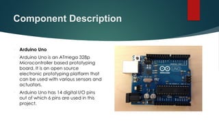
ArduinoUno
Arduino Uno is an ATmega 328p
Microcontroller based prototyping
board. It is an open source
electronic prototyping platform that
can be used with various sensors and
actuators.
Arduino Uno has 14 digital I/O pins
out of which 6 pins are used in this
project.
6.
Component Description
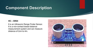
HC– SR04
It is an Ultrasonic Range Finder Sensor.
It is a non-contact based distance
measurement system and can measure
distance of 2cm to 4m.
7.
Component
Description
L293D
Itis a motor driver which can provide bi-
directional drive current for two motors.
Servo Motor
The Tower Pro SG90 is a simple Servo Motor
which can rotate 90 degrees in each
direction (approximately 180 degrees in
total).
8.
Design of
Obstacle
Avoiding
Robot using
Arduino
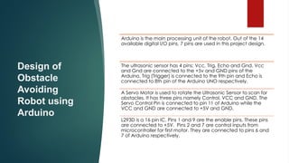
Arduinois the main processing unit of the robot. Out of the 14
available digital I/O pins, 7 pins are used in this project design.
The ultrasonic sensor has 4 pins: Vcc, Trig, Echo and Gnd. Vcc
and Gnd are connected to the +5v and GND pins of the
Arduino. Trig (Trigger) is connected to the 9th pin and Echo is
connected to 8th pin of the Arduino UNO respectively.
A Servo Motor is used to rotate the Ultrasonic Sensor to scan for
obstacles. It has three pins namely Control, VCC and GND. The
Servo Control Pin is connected to pin 11 of Arduino while the
VCC and GND are connected to +5V and GND.
L293D is a 16 pin IC. Pins 1 and 9 are the enable pins. These pins
are connected to +5V. Pins 2 and 7 are control inputs from
microcontroller for first motor. They are connected to pins 6 and
7 of Arduino respectively.
9.
Design of
Obstacle
Avoiding
Robot using
Arduino
Similarly,pins 10 and 15 are control inputs from
microcontroller for second motor. They are connected to
pins 5 and 4 of Arduino. Pins 4, 5, 12 and 13 of L293D are
ground pins and are connected to Gnd.
First motor (consider this as the motor for left wheel) is
connected across the pins 3 and 6 of L293D. The second
motor, which acts as the right wheel motor, is connected to
11 and 14 pins of L293D.
The 16th pin of L293D is Vcc1. This is connected to +5V. The
8th pins is Vcc2. This is the motor supply voltage. This can be
connected anywhere between 4.7V and 36V. In this project,
pin 8 if L293D is connected to +5V supply.
Motor Driver boards are available with on – board 5V
voltage regulator. A similar one is used in the project.
10.
Working
Before going toworking of the project, it is important to
understand how the ultrasonic sensor works. The basic
principle behind the working of ultrasonic sensor is as follows:
Using an external trigger signal, the Trig pin on ultrasonic
sensor is made logic high for at least 10µs. A sonic burst from
the transmitter module is sent. This consists of 8 pulses of
40KHz.
The signals return back after hitting a surface and the
receiver detects this signal. The Echo pin is high from the
time of sending the signal and receiving it. This time can be
converted to distance using appropriate calculations.
The aim of this project is to implement an obstacle avoiding
robot using ultrasonic sensor and Arduino. All the
connections are made as per the circuit diagram. The
working of the project is explained below.
11.
WORKING
When the robotis powered on, both the motors of the robot will
run normally and the robot moves forward. During this time, the
ultrasonic sensor continuously calculate the distance between the
robot and the reflective surface.
This information is processed by the Arduino. If the distance
between the robot and the obstacle is less than 15cm, the Robot
stops and scans in left and right directions for new distance using
Servo Motor and Ultrasonic Sensor. If the distance towards the left
side is more than that of the right side, the robot will prepare for a
left turn. But first, it backs up a little bit and then activates the Left
Wheel Motor in reversed in direction.
Similarly, if the right distance is more than that of the left distance,
the Robot prepares right rotation. This process continues forever
and the robot keeps on moving without hitting any obstacle.
12.
Applications
Obstacle avoidingrobots can be used in
almost all mobile robot navigation systems.
They can be used for household work like
automatic vacuum cleaning.
They can also be used in dangerous
environments, where human penetration
could be fatal.