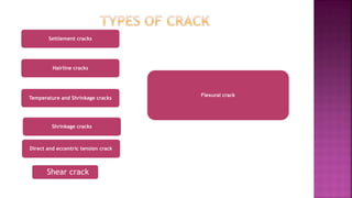
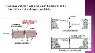
by
KUMAR ANJNEYA
1711CE03
MTECH
INDIAN INSTITUTE OF TECHNOLOGY PATNA
 Why Concrete Cracks?
 Generally, it is assumed that cracks are due to some problems
in the foundation, whereas it is not always correct and should
not be considered failure of structure or improper design or
bad quality work. Generally, 1/16 to 1/4-inch-wide cracks is
acceptable limits.
 The crack width of a flexural member is calculated to satisfy a
limit state of serviceability. Among prestressed concrete
members, there is cracking under service loads only for Type 3
members. Hence the calculation of crack width is relevant
only for Type 3 members.
 The crack width is calculated for the cracks due to bending
which occur at the bottom or top surfaces of a flexural
member.
• 1) Amount of prestress
• 2) Tensile stress in the
longitudinal bars
• 3) Thickness of the concrete
cover
• 4) Diameter and spacing of
longitudinal bars
• 5) Depth of member and
location of neutral axis
• 6) Bond strength
• 7) Tensile strength of concrete.
Shrinkage cracks
Hairline cracks
Settlement cracks
Temperature and Shrinkage cracks
Direct and eccentric tension crack
Flexural crack
Shear crack
 The flexural cracks start from the tension face and propagate
perpendicular to the axis of the member.
 If these cracks are wide, it leads to corrosion of the
reinforcing bars and prestressed tendons. Also, the cracks
tend to widen under sustained load or cyclic load.
IS:456 - 2000,Annex F, gives a procedure to determine flexural
crack width. The design crack width (Wcr) at a selected level on
the surface of the section with maximum moment is given as
follows.
The notations in the previous equation are as follows.
acr = shortest distance from the selected level on the surface to a longitudinal bar
Cmin = minimum clear cover to the longitudinal bar
h = total depth of the member
x = depth of the neutral axis
εm = average strain at the selected level
The values of Cmin and h are obtained from the section of the member.
Method of Calculation
 EVALUATION OF acr
 The location of crack width calculation can be at the soffit
or the sides of a beam. The value of acr depends on the
selected level. The following sketch shows the values of acr
at a bottom corner (A), at a point in the soffit (B) and at a
point at the side (C).
Evaluation of x
and εm
The values of x and εm are calculated
based on a sectional analysis under
service loads. The sectional analysis
should consider the tension carried by
the uncracked concrete in between two
cracks. The stiffening of a member due
to the tension carried by the concrete is
called the tension stiffening effect.
The value of εm is considered to be an
average value of the strain at the
selected level over the span. The
following sketch illustrates the cracking
and the uncracked concrete in a flexural
member.
The limits of crack width are as
follows.
Crack width ≤ 0.2 mm for
moderate and mild environments
≤ 0.1 mm for severe
environment.
 Limiting the tensile stress in steel
 Minimising the spacing of reinforcing bars
 Providing bars as close as possible to the concrete surface in
tension zone (including side face reinforcement in relatively
deep beams - Concrete cracks when tensile strain exceeds
.0001
 thermal and shrinkage cracks can
Be controlled by contraction and
 thermal and shrinkage cracks can be controlled by
contraction and and expansion joints.
 Cracks distance and width in reinforced concrete membranes: experimental
results from cyclic loading histories G. Ruocci, C. Rospars
 What is the Crack Width in Concrete Structures to Prevent leakage. Author(s): L.
G. Mrazek
 IS 456: Plain and Reinforced Concrete - Code of Practice
 Rcc concrete – b.c.punmia
 Nptel video lectures.
 Dr. Amlan K Sengupta and Prof. Devdas Menon- rcc and prestressed concrete
crack control and crack width estimation

crack control and crack width estimation

  • 1.
  • 2.
     Why ConcreteCracks?  Generally, it is assumed that cracks are due to some problems in the foundation, whereas it is not always correct and should not be considered failure of structure or improper design or bad quality work. Generally, 1/16 to 1/4-inch-wide cracks is acceptable limits.  The crack width of a flexural member is calculated to satisfy a limit state of serviceability. Among prestressed concrete members, there is cracking under service loads only for Type 3 members. Hence the calculation of crack width is relevant only for Type 3 members.  The crack width is calculated for the cracks due to bending which occur at the bottom or top surfaces of a flexural member.
  • 3.
    • 1) Amountof prestress • 2) Tensile stress in the longitudinal bars • 3) Thickness of the concrete cover • 4) Diameter and spacing of longitudinal bars • 5) Depth of member and location of neutral axis • 6) Bond strength • 7) Tensile strength of concrete.
  • 4.
    Shrinkage cracks Hairline cracks Settlementcracks Temperature and Shrinkage cracks Direct and eccentric tension crack Flexural crack Shear crack
  • 5.
     The flexuralcracks start from the tension face and propagate perpendicular to the axis of the member.  If these cracks are wide, it leads to corrosion of the reinforcing bars and prestressed tendons. Also, the cracks tend to widen under sustained load or cyclic load.
  • 6.
    IS:456 - 2000,AnnexF, gives a procedure to determine flexural crack width. The design crack width (Wcr) at a selected level on the surface of the section with maximum moment is given as follows. The notations in the previous equation are as follows. acr = shortest distance from the selected level on the surface to a longitudinal bar Cmin = minimum clear cover to the longitudinal bar h = total depth of the member x = depth of the neutral axis εm = average strain at the selected level The values of Cmin and h are obtained from the section of the member. Method of Calculation
  • 7.
     EVALUATION OFacr  The location of crack width calculation can be at the soffit or the sides of a beam. The value of acr depends on the selected level. The following sketch shows the values of acr at a bottom corner (A), at a point in the soffit (B) and at a point at the side (C).
  • 9.
    Evaluation of x andεm The values of x and εm are calculated based on a sectional analysis under service loads. The sectional analysis should consider the tension carried by the uncracked concrete in between two cracks. The stiffening of a member due to the tension carried by the concrete is called the tension stiffening effect. The value of εm is considered to be an average value of the strain at the selected level over the span. The following sketch illustrates the cracking and the uncracked concrete in a flexural member.
  • 11.
    The limits ofcrack width are as follows. Crack width ≤ 0.2 mm for moderate and mild environments ≤ 0.1 mm for severe environment.
  • 12.
     Limiting thetensile stress in steel  Minimising the spacing of reinforcing bars  Providing bars as close as possible to the concrete surface in tension zone (including side face reinforcement in relatively deep beams - Concrete cracks when tensile strain exceeds .0001  thermal and shrinkage cracks can Be controlled by contraction and
  • 13.
     thermal andshrinkage cracks can be controlled by contraction and and expansion joints.
  • 14.
     Cracks distanceand width in reinforced concrete membranes: experimental results from cyclic loading histories G. Ruocci, C. Rospars  What is the Crack Width in Concrete Structures to Prevent leakage. Author(s): L. G. Mrazek  IS 456: Plain and Reinforced Concrete - Code of Practice  Rcc concrete – b.c.punmia  Nptel video lectures.  Dr. Amlan K Sengupta and Prof. Devdas Menon- rcc and prestressed concrete