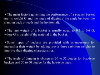
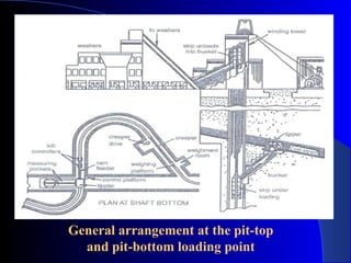
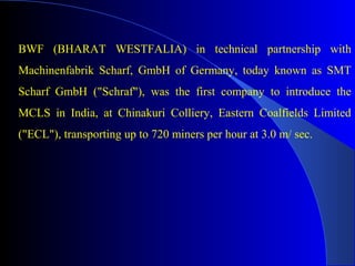
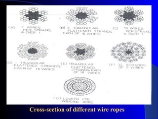
This document summarizes different types of wire ropes used in mining. It discusses the materials, construction, and properties of various wire ropes including stranded ropes, non-stranded locked coil ropes, and flat ropes. The key types are distinguished by their core, wire thickness, number of wires, and lay pattern. Appropriate wire rope selection depends on factors like flexibility, strength, and whether it will be used for standing or running applications.
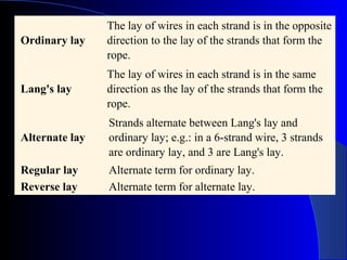
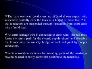
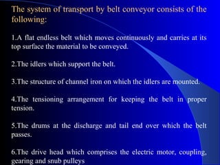
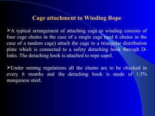
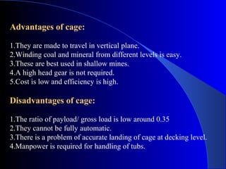
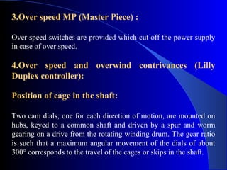
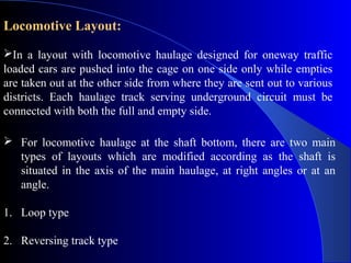
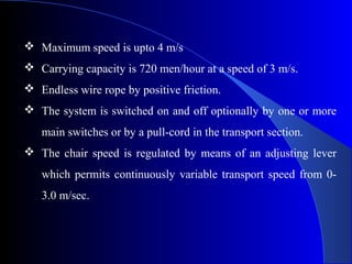
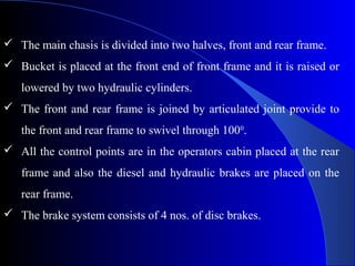
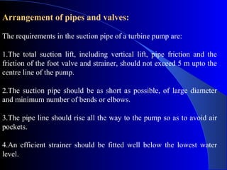
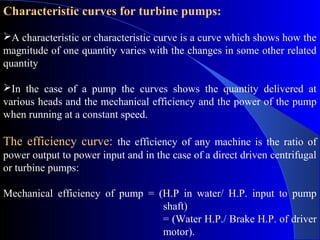
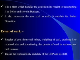
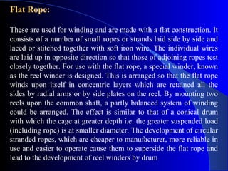
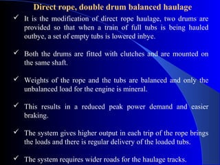
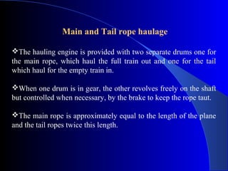
![The specification of a wire rope type – including the number
of wires per strand, the number of strands, and the lay of the rope
– is documented using a commonly accepted coding system,
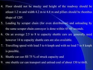
consisting of a number of abbreviations.
The rope 6x19 FC RH OL FSWR [where 6- Number of strands
that make up the rope, 19 - Number of wires that make up each
strand, FC- Fibre core, RH OL FSWR - Right hand Ordinary lay
Flexible steel wire rope].](https://image.slidesharecdn.com/miningmachinarynitrourkela-130409105221-phpapp01/85/Mining-machinary-nit-rourkela-11-320.jpg)
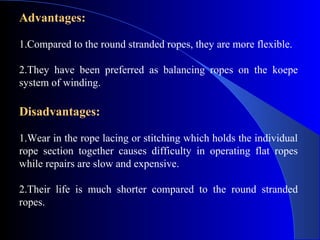
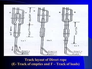
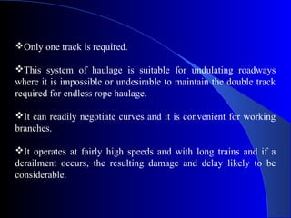
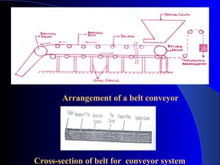
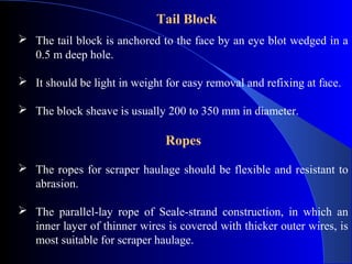
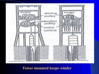
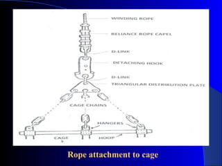
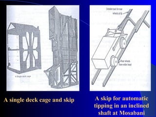
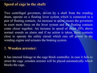
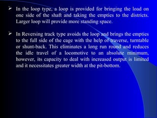
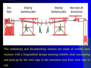
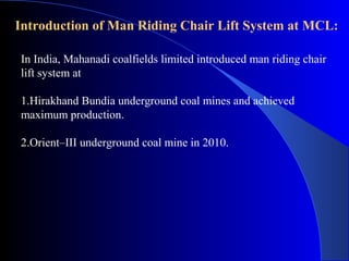
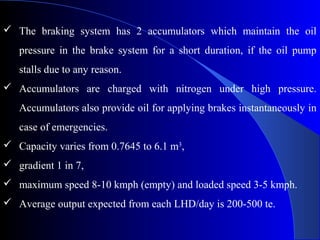
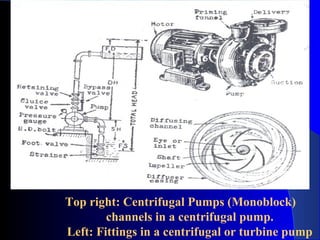
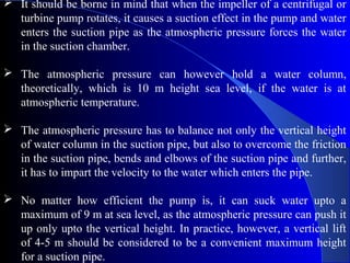
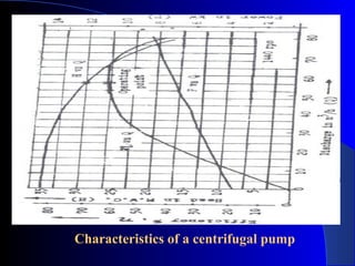
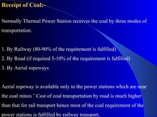
![Diesel Locomotive
It is commonly used. Their weight ranges from 3 to 15 te and
the power from 15 to 75 KW.
The power unit is a diesel engine with 2,3 or 4 cylinders of 4
stroke cycle, compression ignition type. Heavy duty locos are
of 6 cylinders.
Locos used in an underground coal mines have the power unit
in a flameproof enclosure as a safeguard against ignition of
firedamp.
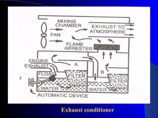
The intake air going to the engine passes first through a filter
and then through a flame trap. Similar flame trap is fitted on
the exhaust side of the diesel engine [Exhaust conditioner].](https://image.slidesharecdn.com/miningmachinarynitrourkela-130409105221-phpapp01/85/Mining-machinary-nit-rourkela-79-320.jpg)