This document discusses various underground mine transportation systems, including:
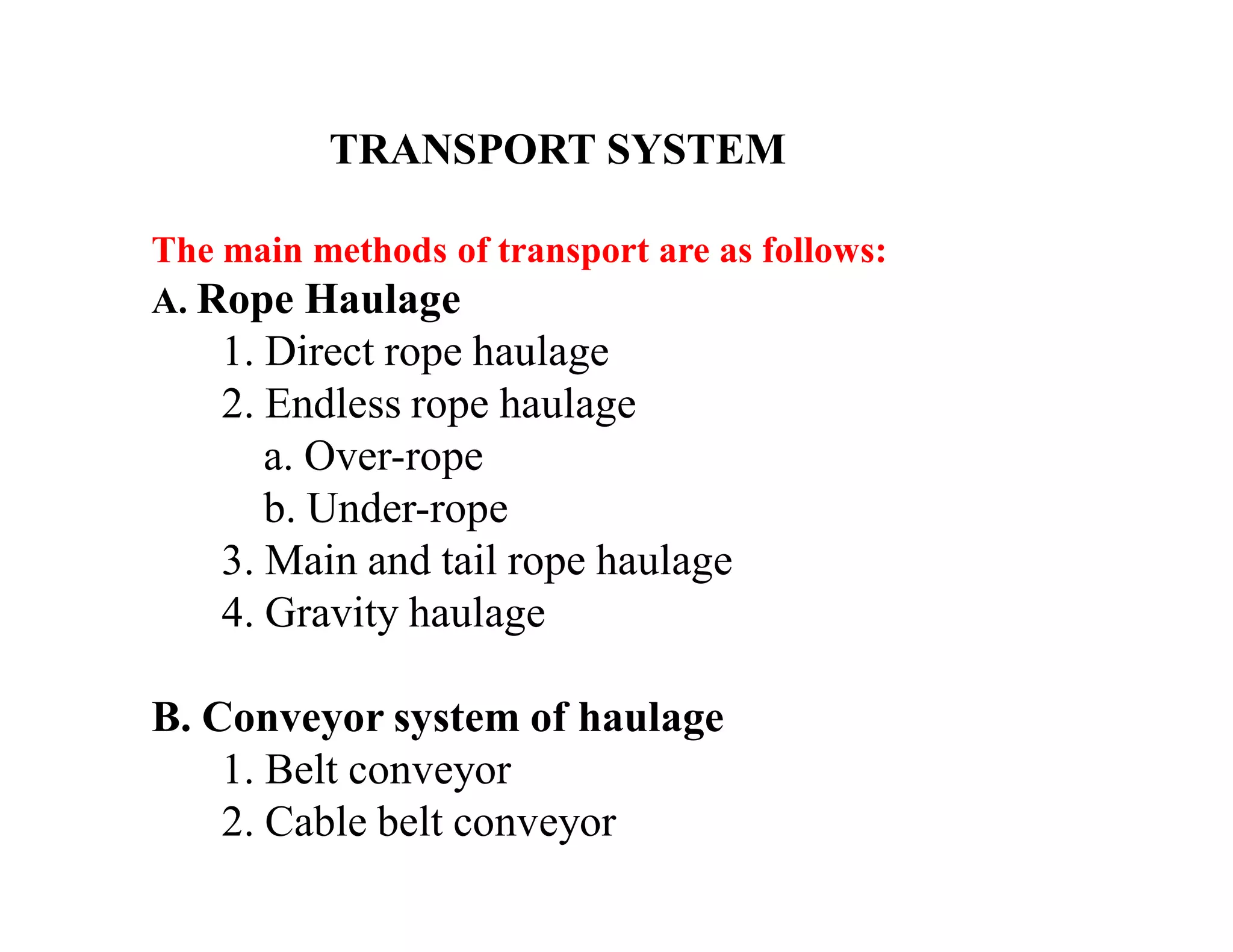
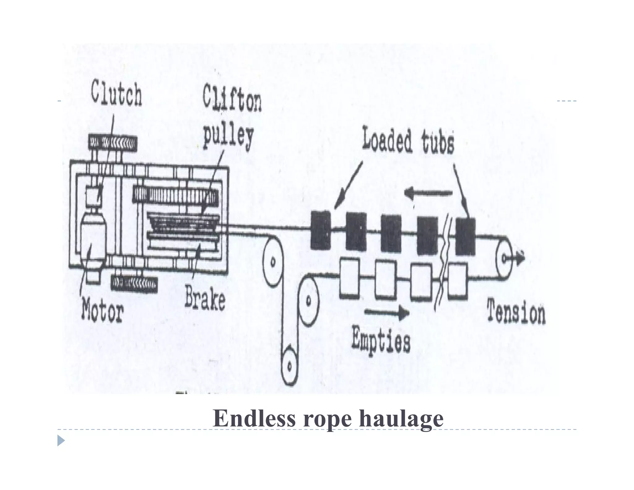
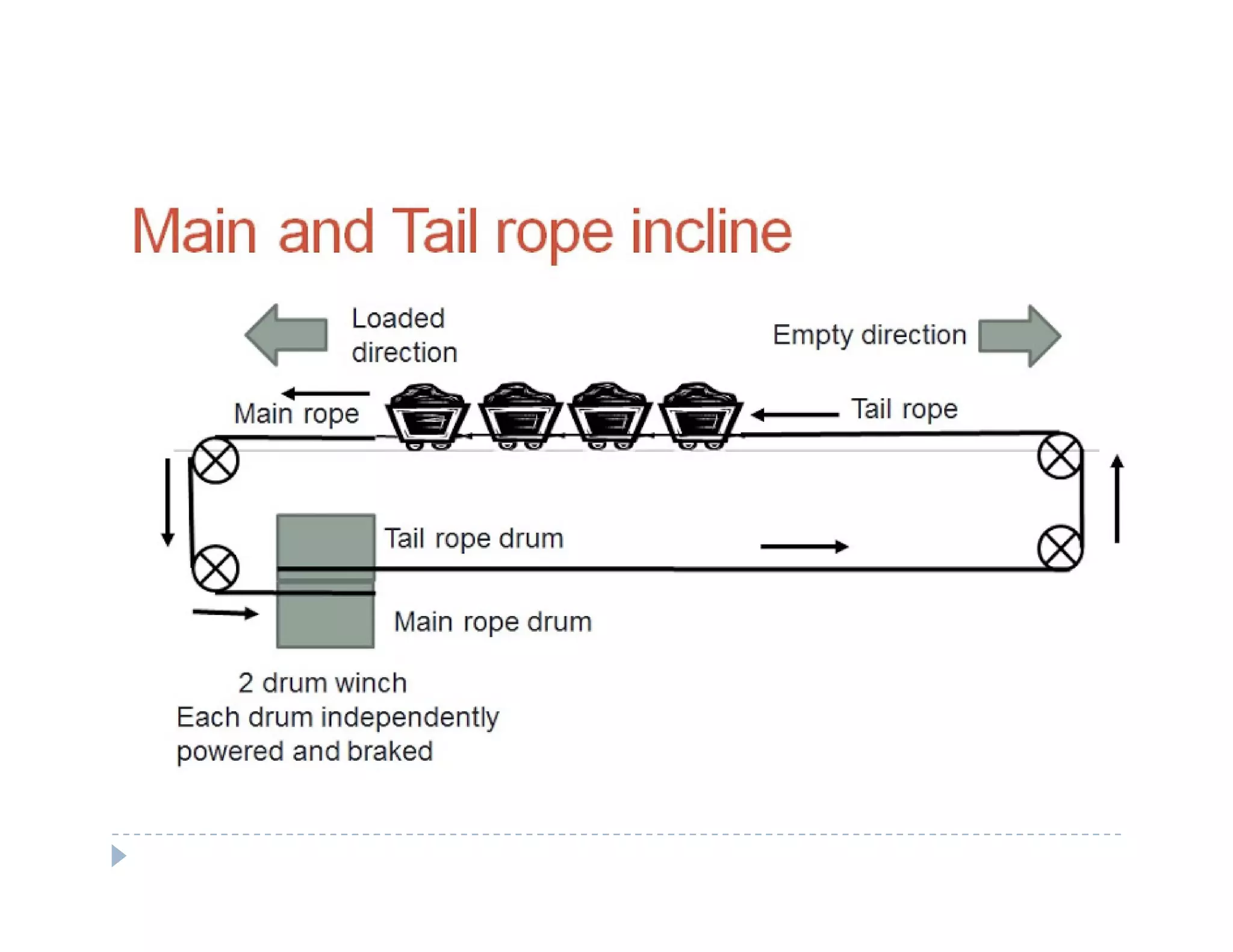
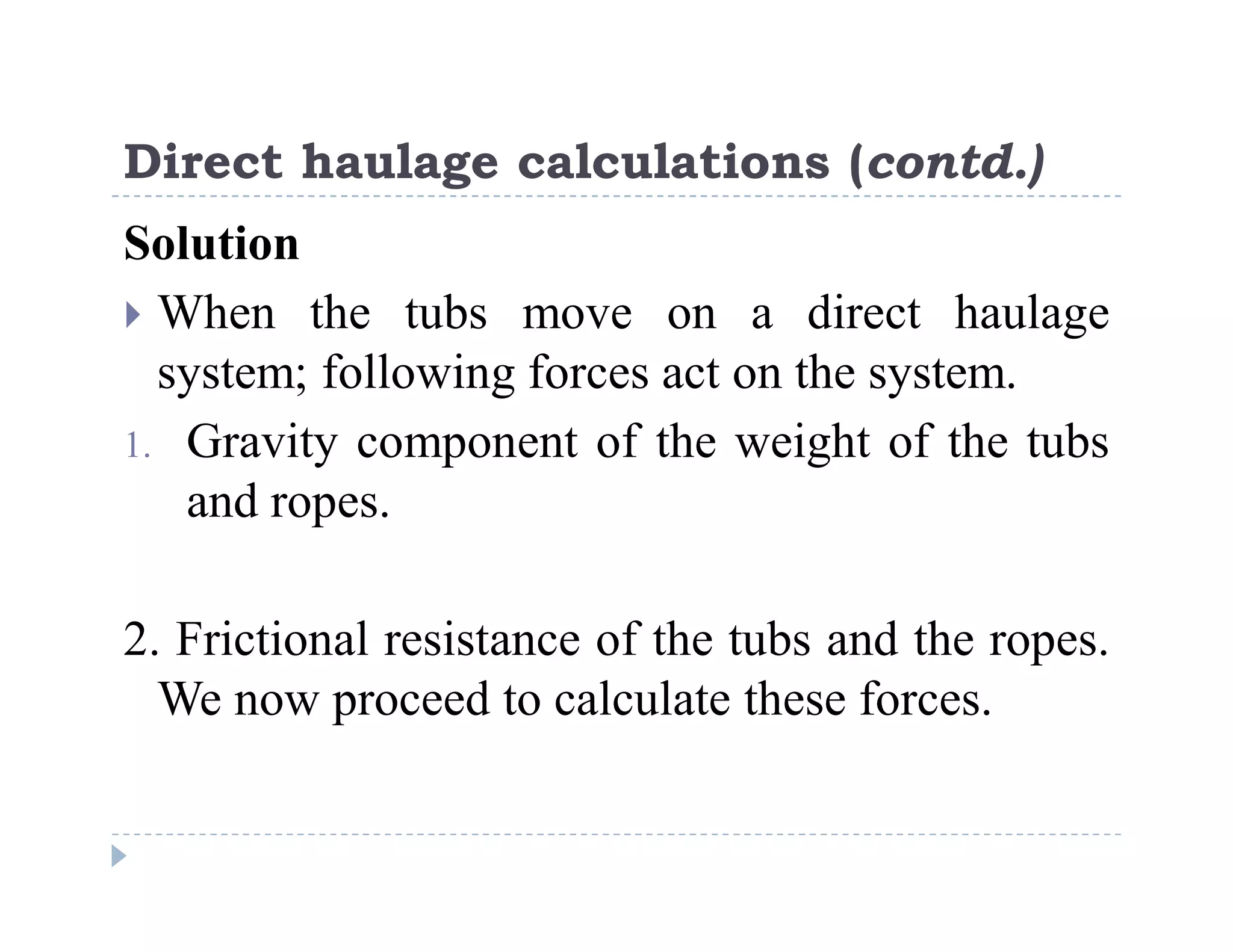
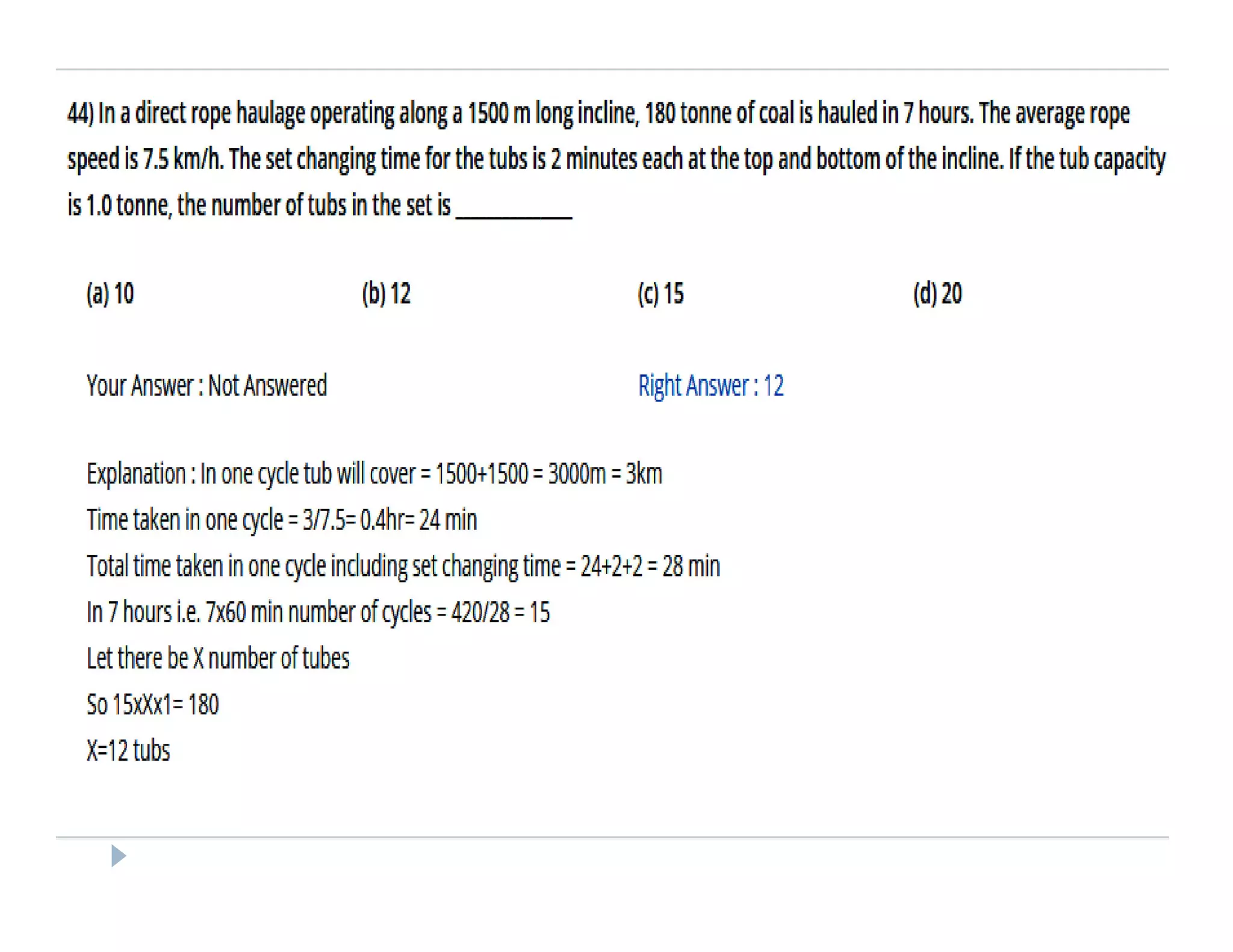
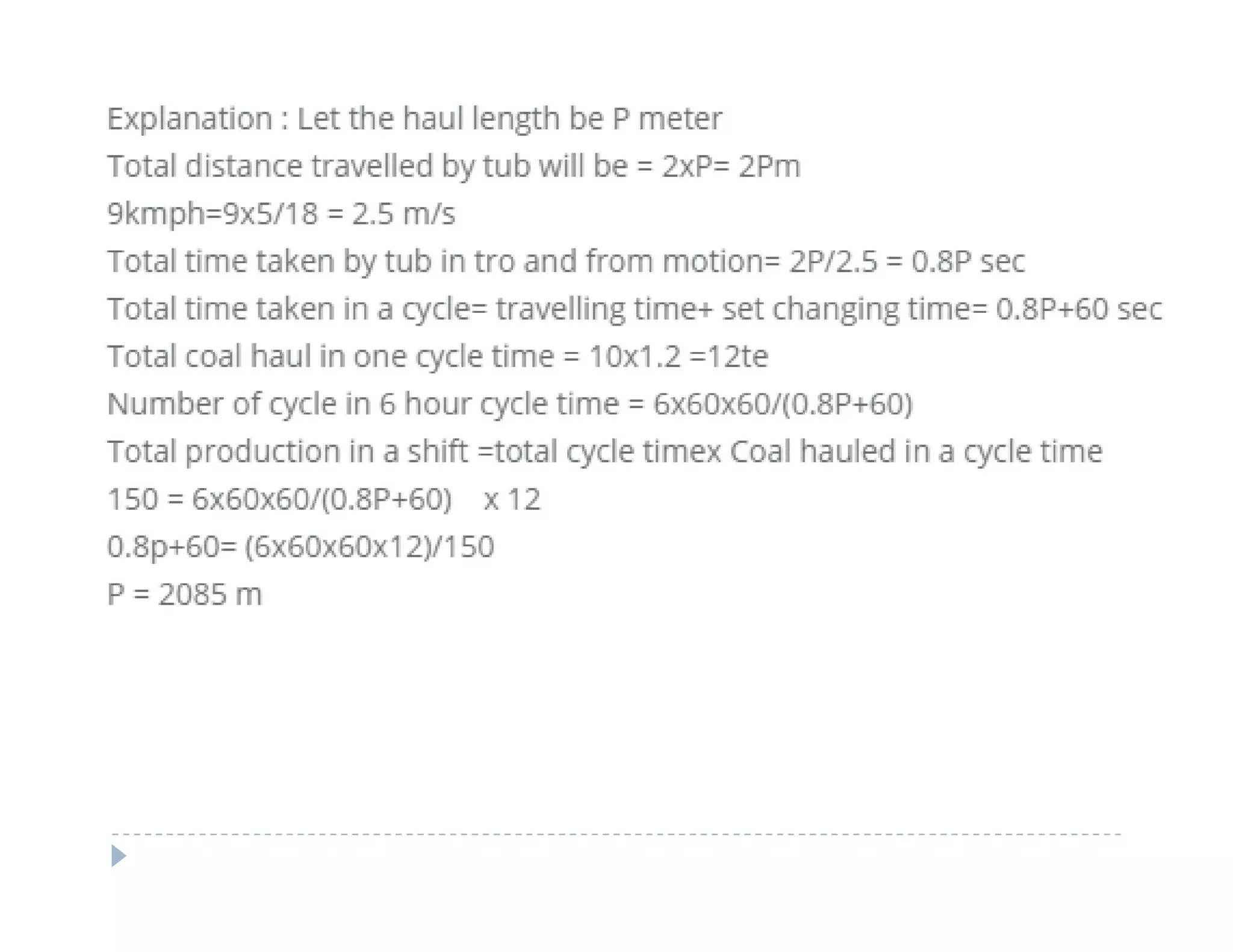
1. Rope haulage systems like direct rope haulage, endless rope haulage, and main and tail rope haulage.
2. Conveyor systems for haulage including belt conveyors and chain conveyors.
3. Locomotive haulage using diesel, electric, or compressed air locomotives.
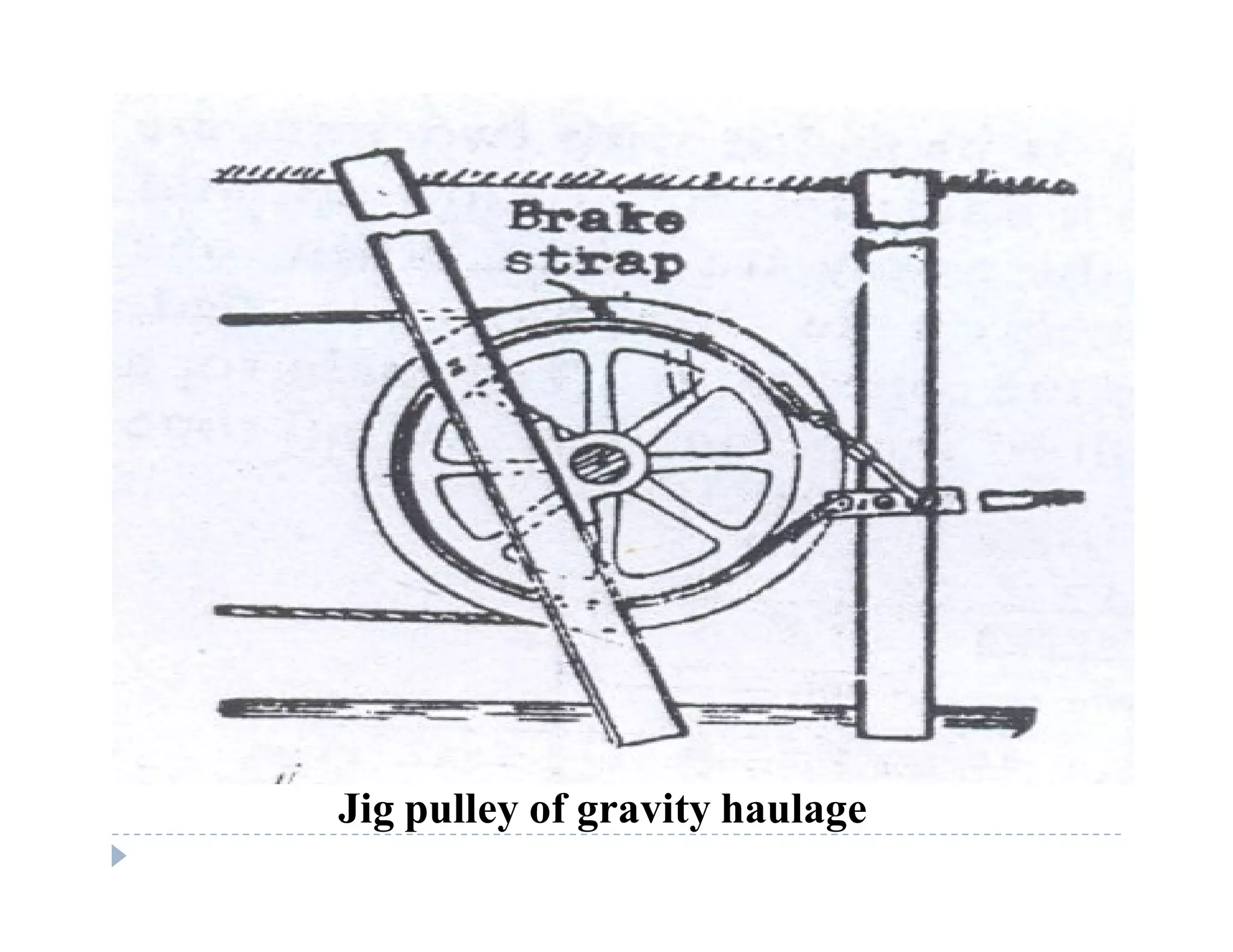
4. Gravity or self-acting haulage which uses the force of gravity down an inclined plane without an external power source.
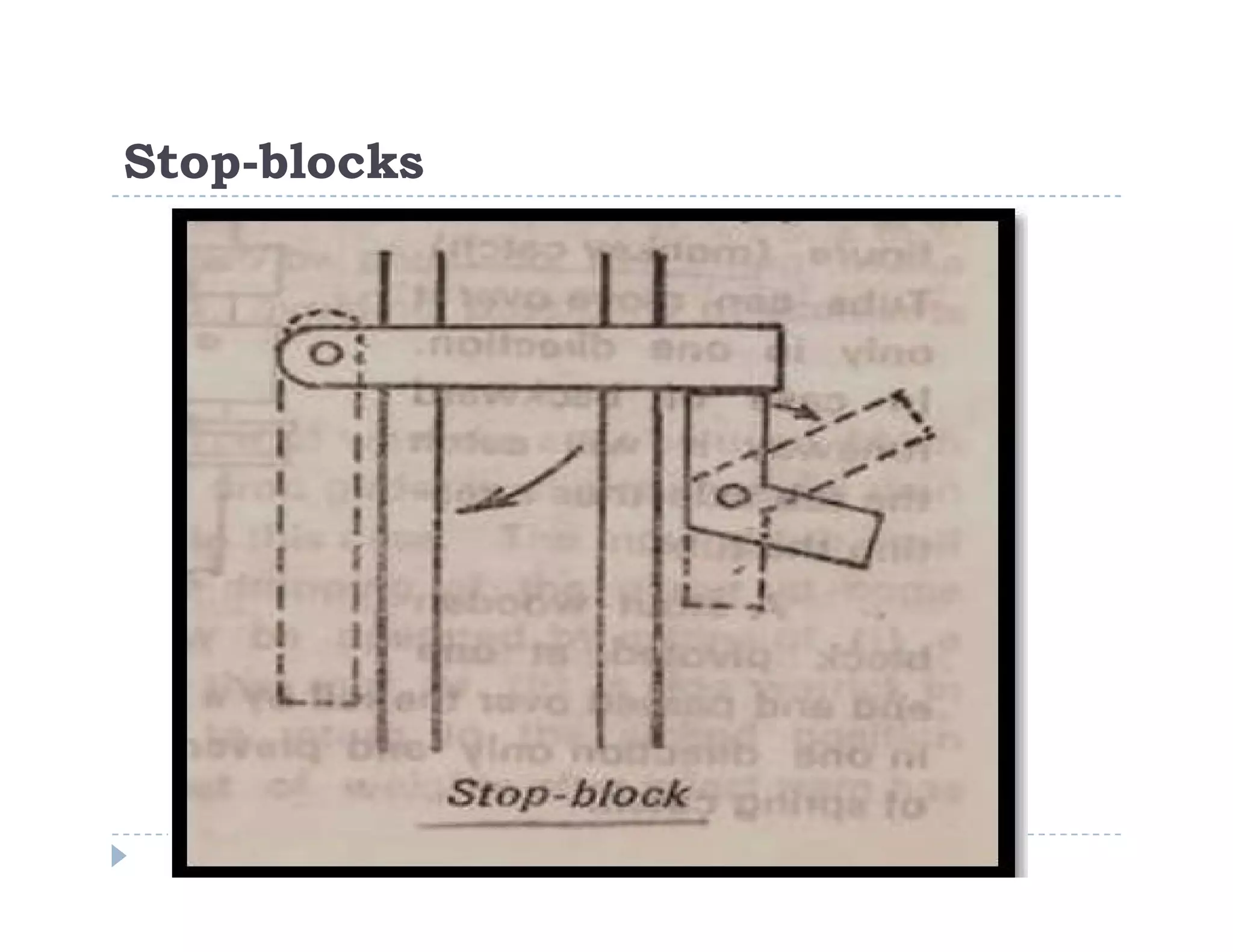
Safety devices for haulage systems are also covered, such as stop-blocks and buffers to prevent runaway tubs.