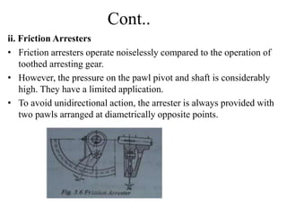
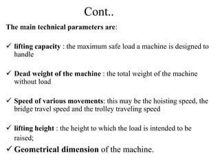
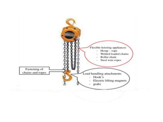
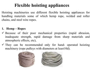
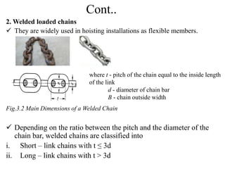
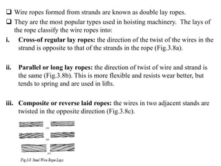
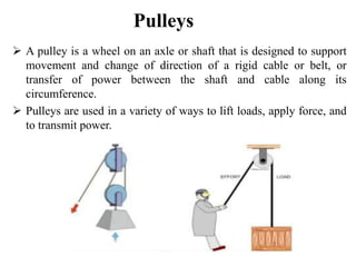
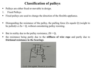
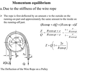
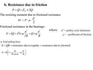
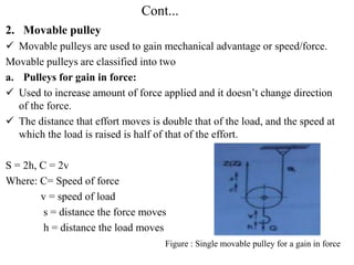
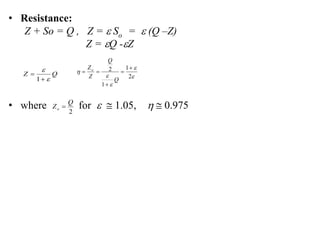
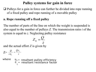
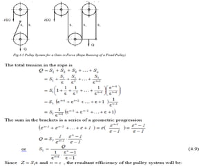
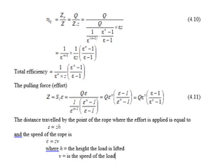
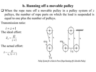
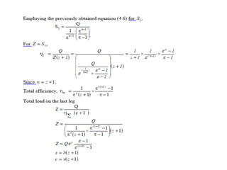
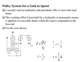
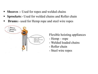
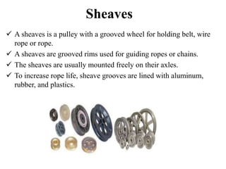
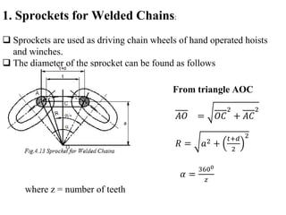
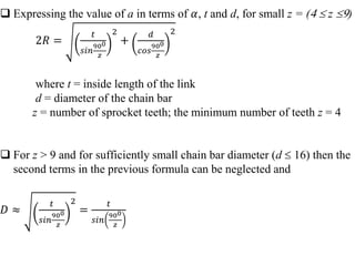
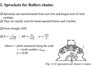
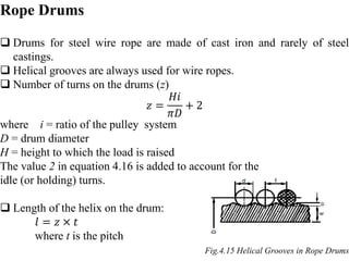
This document provides information on various types of hoisting equipment and their components. It discusses theory of hoisting equipment including flexible hoisting appliances like pulleys, chains, and wire ropes. There are three main groups of hoisting equipment - hoisting machines, cranes, and elevators. Cranes combine a hoisting mechanism with a frame to lift and move loads vertically and horizontally. Selection criteria and technical parameters for hoisting equipment like lifting capacity, speed, and dimensions are also outlined. The document also covers wire rope construction, selection, and fastening of chains and ropes. Pulleys are defined as wheels that support movement and change of direction of cables or belts to lift loads or transmit power.

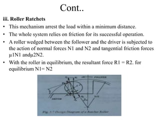
![ Hoisting machines are periodic-action machines and their hourly
capacity can be determined from:
n= number of machine cycles/ hour
Q= weight of live load [tons]
Qhr =Hourly capacity [tons/h]
When handling bulk material, the weight of live
Q = V x ϕ x ɣ
Where
V= capacity of bucket, [m3]
ϕ = filling factor
ɣ= specific weight [t/m3]
Q
n
Qhr
](https://image.slidesharecdn.com/hoistingeuipmentpartone-230606031924-f19799bc/85/hoisting-euipment-part-one-pptx-7-320.jpg)
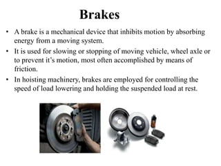
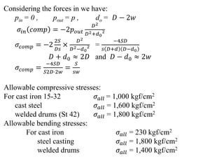
![ The total load lifting capacity of the machine will be:
𝑄𝑡𝑜𝑡= 𝑄 + 𝐺
Where:- Q = live load [tons]
G = weight of bucket, grab, etc. [tons]
The number of cycles per hour is:
Where
𝑡𝑜𝑝= operation time
𝑡𝑠𝑡=starting time
𝑡𝑐𝑠=constant speed time
𝑡𝑟= retardation time
𝑡𝑖𝑑𝑒𝑙=time lost in grabbing and discharging the load
t= cycle time[second]
t
n
3600
r
cs
st
op t
t
t
t
idle
op t
t
t
](https://image.slidesharecdn.com/hoistingeuipmentpartone-230606031924-f19799bc/85/hoisting-euipment-part-one-pptx-8-320.jpg)
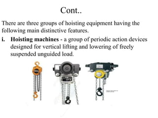
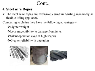
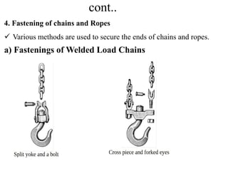
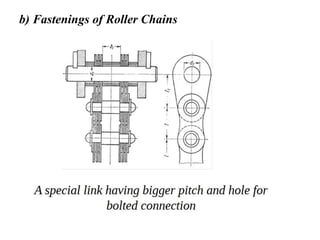
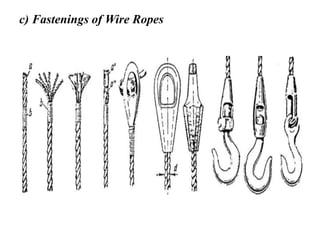
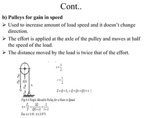
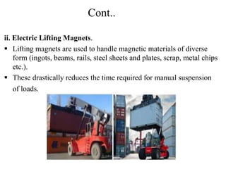
![Cont..
By the mode of manufacture and number of strands, hemp ropes are
classified as
i. plain-laid
ii. cable-laid
The latter being from twisted from three ordinary ropes twisted from
three ordinary ropes.
Where F = load on the rope [kgf]
d = nominal rope diameter [cm]
For white rope σ𝑏𝑟=100 kgf/cm2 and for tarred rope σ𝑏𝑟= 90 kgf/cm2
br
2
4
d
=
F
](https://image.slidesharecdn.com/hoistingeuipmentpartone-230606031924-f19799bc/85/hoisting-euipment-part-one-pptx-11-320.jpg)
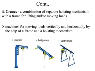
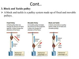
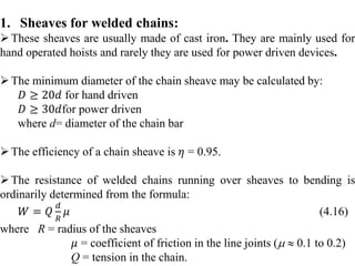
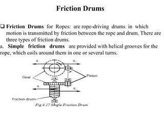
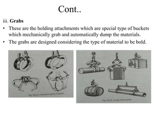
![Selection of Load Chains
Chains are checked for tension taking a higher safety factor to
take care of the complexity of the problem.
Where:-
o 𝐹𝑏𝑟=breaking load [kgf] (given in manufacturer's catalogue and
in standards)
o K = factor of safety
o 𝐹𝑠=safe load carried by chains [kgf
the safety factor K should be taken from 3 to 8.
K
F
F br
s ](https://image.slidesharecdn.com/hoistingeuipmentpartone-230606031924-f19799bc/85/hoisting-euipment-part-one-pptx-15-320.jpg)
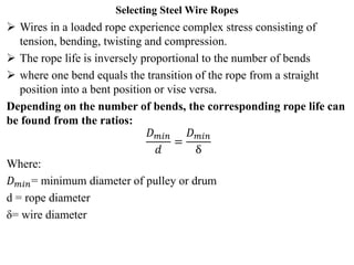
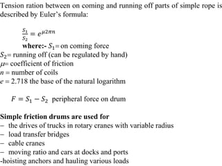
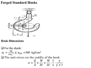
![Strength of Wire Rope
• Total stress in the loaded wire rope in its bent part is the sum of the
tensile and bending stress.
Where
σ𝑏𝑟 =breaking strength [kgf/cm2 ]
K = rope factor of safety
S = tension in the rope [kgf]
A = useful area of the cross-section [cm2]
I = moment of inertia [cm4]
M = bending moment [kgf.cm]
c = centroid [cm]
= Corrected rope elastic modulus 800,000kg/cm2
E = elastic modulus of rope wire material = 2,100,000kg/cm
I
Mc
A
S
ben
ten
min
min D
E
2
I
M
EI
M
1
D
2
min
min
ben
D
E
2
D
E
2
I
Mc
2
c
min
br
D
'
E
+
A
S
K
E
8
3
'
E ](https://image.slidesharecdn.com/hoistingeuipmentpartone-230606031924-f19799bc/85/hoisting-euipment-part-one-pptx-29-320.jpg)
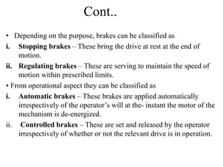
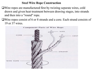
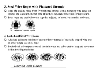
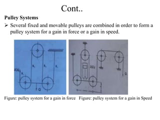
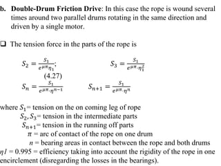
![Ropes subjected to only tensile forces
𝐹𝑏𝑟= breaking strength [kgf]
𝐹𝑆 =maximum permissible tensile force in the rope [kgf]
K = factor of safety
Values of K for Different Operating Conditions
K
F
F br
s
Drive Duty K e
Hand Light (L) 4.5 18
Power
Light (L) 5.0 20
Medium (M) 5.5 25
Heavy (H) 6.0 30
Very Heavy (VH) 6.0 30](https://image.slidesharecdn.com/hoistingeuipmentpartone-230606031924-f19799bc/85/hoisting-euipment-part-one-pptx-31-320.jpg)
![.
where is stiffness of rope
where d - rope diameter [cm]
D - pulley diameter [cm
The magnitude of is called pulley factor of resistance, and
Q
Z
1
is the pulley efficiency
Thus
R
d
cos
R
e '
2
1
cos
2
R
e
10
1
.
0
cos
2
D
d
R
e
it can be empirically determined by experiment and was found
to be](https://image.slidesharecdn.com/hoistingeuipmentpartone-230606031924-f19799bc/85/hoisting-euipment-part-one-pptx-39-320.jpg)
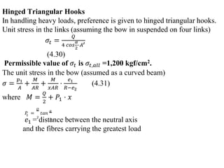
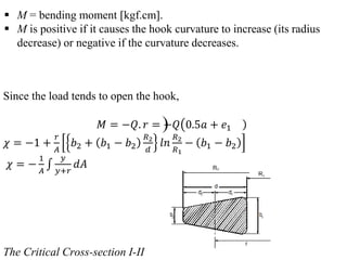
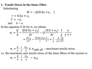
![where
= unit stress for the fibre at a distance y from the neutral axis
[kgf/cm2]
Q = load on the hook kgf
A = area of the critical cross-section here cross-section I cm
r = radius of curvature of the neutral axis at the critical cross-section
cm
x = factor depending on the shape of the cross-section and the
curvature of the beam
y = distance from the fibre to the neutral axis.
y is negative if the fibre is between the centre of curvature and the
natural axis; and is positive if the fibre is on the other side of the neutral
axis,cm](https://image.slidesharecdn.com/hoistingeuipmentpartone-230606031924-f19799bc/85/hoisting-euipment-part-one-pptx-76-320.jpg)
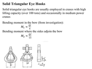
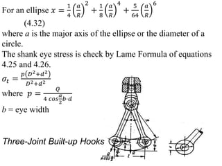
![Tensile force acting on the sides:
𝑃 =
𝑄
2 𝑐𝑜𝑠
𝛼
2
where 𝛼 = angle between the inclined sides
𝓁 = bow spans measured along the neutral line of the sections.
Q = load
Compressive force 𝑃1 acting on the bow is
𝑃1 =
𝑄
2
𝑡𝑎𝑛
𝛼
2
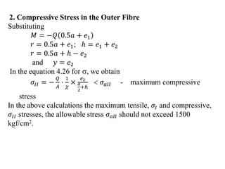
Maximum stress in the bow
𝜎 =
𝑀𝑏𝑒𝑛𝑑
𝑤
+
𝑃1
𝐴
< 𝜎𝑎𝑙𝑙
where 𝑀𝑏𝑒𝑛𝑑 ≈
𝑄𝑙
6
+ 𝑃1𝑥 [kgf.cm]
w = Sectional modulus[cm3]
A = Cross-sectional area [cm2]
x = moment arm of the compressive force𝑃1
The safe stress 𝜎𝑎𝑙𝑙 = 800kgf/cm2](https://image.slidesharecdn.com/hoistingeuipmentpartone-230606031924-f19799bc/85/hoisting-euipment-part-one-pptx-81-320.jpg)