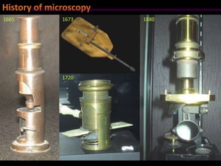
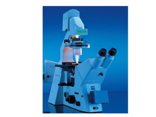
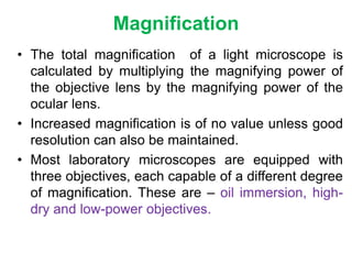
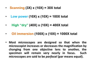
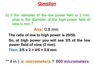
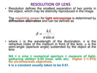
Microscopy-II
Md. Saiful Islam
B.Pharm, M.Pharm (PCP)
North South University
Join Facebook Group: Pharmacy Universe
History of microscopy
1673
1720
18801665
History of microscopy
The first commersial microscopes
• 1939 Elmiskop by Siemens Company
• 1941 microscope by Radio corporation of America (RCA)
– First instrument with stigmators to correct for
astigmatism. Resolution limit below 10 Å.
Elmiskop I
Refraction
• Refraction is the bending of light as it passes
from one medium to another of different density.
• Immersion oil, which has the same index of
refraction as glass, is used to replace air and to
prevent refraction at a glass-air interface.
• An example would be when one looks at objects
just below the surface of water in a pond or other
body of water…..the objects become refracted or
“distorted” from the true image.
Magnification
• The total magnification of a light microscope is
calculated by multiplying the magnifying power of
the objective lens by the magnifying power of the
ocular lens.
• Increased magnification is of no value unless good
resolution can also be maintained.
• Most laboratory microscopes are equipped with
three objectives, each capable of a different degree
of magnification. These are – oil immersion, high-
dry and low-power objectives.
• Scanning (3X) x (10X) = 30X total
• Low power (10X) x (10X) = 100X total
• High “dry” (40X) x (10X) = 400X total
• Oil immersion (100X) x (10X) = 1000X total
• Most microscopes are designed so that when the
microscopist increases or decreases the magnification by
changing from one objective lens to another, the
specimen will remain very nearly in focus. Such
microscopes are said to be parfocal (par means equal).
Question
ocular power = 10x
low power objective = 20x
high power objective = 50x
a) What is the highest magnification you could get
using this microscope ?
Ans:500x
Ocular x high power = 10 x 50 = 500. (We can
only use 2 lenses at a time, not all three.)
b) If the diameter of the low power field is 2 mm,
what is the diameter of the high power field of
view in mm ?
Ans: 0.8 mm
The ratio of low to high power is 20/50.
So, at high power you will see 2/5 of the low
power field of view (2 mm).
Then, 2/5 x 2 = 4/5 = 0.8 mm
** if in ) in micrometers ? 800 micrometers
Question
C) If 10 cells can fit end to end in the low
power field of view, how many of those cells
would you see under high power ?
Ans: 4 cells.
At high power we would see 2/5 of the low
field.
So, 2/5 x 10 cells = 4 cells would be seen under
high power.
Question
Parts of a Compound
Microscope
Lenses:
Ocular Lens: eyepiece lens
Objective Lens: can be low, medium or high power
Look at magnification on lens
Lower power is smaller in size
Letting in Light:
• Mirror or Illuminator:
directs light up through the
specimen
• Diaphragm: regulates
amount of light
– Disk with different sized
“iris” or openings
• Arm: connects stage and body
tube
• Stage: platform with opening
over which a specimen is placed
(clips to hold slide)
• Base: supports microscope
• Eyepiece (ocular): part you look
through, holds ocular lens,
magnifies 10x
• Body tube: connects eyepiece &
objective lenses
• Nosepiece: holds objective lenses
(can be turned)
Focusing:
Coarse Adjustment Knob:
use on low power only!!
(never use with high power
you can break your slide!)
Fine Adjustment Knob:
once low power is focused
switch to high power and use
fine adjustment.
Comparing Microscopes
Compound Light Microscope
• Magnification 40x – 1500x.
• 2-D image, inverted, upside down.
• Uses stains to see details (may kill specimen).
• Specimen must be thin to allow light through.
Dissecting Microscope:
• Low magnification 10x – 20x.
• See true image (right side up).
• Specimen can be alive.
• Can use tools for dissecting specimen.
• Binocular (two ocular lens) so you can see 3-D image.
Phase Contrast Microscope:
• This is extremely valuable for studying living unstained
cells and is widely used in applied and theoretical
biological studies.
• It uses a conventional light microscope fitted with a
phase-contrast objective and a phase-contrast
condenser.
• This special optical system makes it possible to
distinguish unstained structures within a cell which
differ slightly in their refractive indices or thickness.
• It is possible to reveal differences in cells and their
structures not identified by other microscopic methods.
Bright Field Microscope:
• The microscopic field is brightly lighted and the
microorganisms appear dark because they absorb
some of the light.
• produces a dark image against a brighter background.
• Cannot resolve structures smaller than about 0.2
micrometer.
• Inexpensive and easy to use.
• Used to observe specimens and microbes but does
not resolve very small specimens, such as viruses.
• In principle, this technique is based on the fact that
light passing through one material and into another
material of a slightly different refractive index or
thickness will undergo a change in phase.
• The differences in phase are translated into
variations in brightness of the structures and hence
are detectable by the eye.
Bright-field image of Amoeba proteus
• Uses a special condenser with an opaque disc
that blocks light from entering the objective lens.
• Light reflected by specimen enters the objective
lens.
• Produces a bright image of the object against a
dark background.
• Used to observe living, unstained preparations.
Dark-field microscope:
Dark-field image of Amoeba proteus
Microscope objectives
Working distance
Numerical Aperture (NA)
•The angle α is the half-aperture angle, which is
expressed as a sine value.
•The sine value of the half-aperture angle multiplied
by the refractive index n of the medium filling the
space between the front lens and the cover slip
gives the numerical aperture (NA).
• NA= n sine α
• With dry objectives the value of n is 1, since 1 is
the refractive index of air. When immersion oil is
used as the medium, then n is 1.56 and if α is 58°,
the NA = n sine α = 1.33.
• The maximum NA for a dry objective is less than 1.0
and oil immersion objectives have an NA value of
slightly greater than 1.0 (1.2-1.4).
• The visible light range is between 400 nm (blue light)
and 700 nm ( red light) .
• Thus it is apparent that the resolving power of the
optical microscope is restricted by the limiting values
of the NA and the wavelength of the visible light.
Limit of resolution
•The limit of resolution is the smallest distance by
which two objects can be separated and still be
distinguishable as two separate objects.
•The greatest resolution in light microscopy is
obtained with the shortest wavelength of the visible
light and an objective with the maximum NA.
•The relationship between NA and resolution can be
expressed as follows:
d=λ/2NA
where, d = resolution and λ= wavelength of light
• Using the values 1.3 for NA and 0.55 μm, the
wavelength of green light, for λ, resolution can
be calculated as follows-
d= 0.55/2X1.30
= 0.21 μm
From these calculations, we can conclude that
the smallest details that can be seen by the
typical light microscope are those having
dimensions of approximately 0.2 μm.
RESOLUTION OF LENS
• Resolution defines the smallest separation of two points in
the object, which may be distinctly reproduced in the image.
The resolving power for light microscope is determined by
diffraction aberration and can be defined as
• where  is the wavelength of the illumination, n is the
refractive index of the medium in front of the lens,  is the
semi-angle (aperture angle) subtended by the object at the
lens
NA = n sinα = numerical aperture = measure of light-
gathering ability= 0.95 (max. with air). Higher (~1.515)
for oil-immersion objectives.
k is a constant usually taken to be 0.61.



sinn
k

Optical Microscope –
 = 50 nm (for white light Illumination)
n sin  = 0.135 (for an oil immersion lens)
Therefore, it is possible to achieve a resolution of
about 250 nm in Optical Microscopes.
• Filters can also be used to enhance the resolving
power of an objective. For light:
– The shorter wavelengths are at the violet-blue-green
end of the spectrum
– The higher wavelengths are at the orange-red of the
spectrum.
Electron microscope
• The electron microscope provides tremendous
useful magnification because of the much higher
resolution obtainable with the extremely short
wavelength of the electron beam used to magnify
the specimen.
• With an electron microscope employing 60 to 80 –
kV electrons , the wavelength is only 0.05°A (
angstrom).
• 1°A equals to 10-8 cm or 10-4 μm.
• It is possible to resolve objectives as small as
10°A.
Electron microscope
• The resolving power of the electron microscope is
more than 100 times that of the light microscope and
it produces a useful magnification up to X 400,000.
• For electron microscopy, the specimen to be
examined is prepared as an extremely thin dry film on
small screens and is introduced into the instrument at
a point between the magnetic condenser and the
magnetic objective.
• The magnified image may be viewed on a fluoroscent
screen through an airtight “window” or recorded on a
photographic plate by a camera built into the
instrument.
Typical Information from Electron Microscope:
• Chemical composition of materials can be obtained
using electron microprobes to produce characteristic
X-ray emissions and electron energy losses.
• Imaging (surface) can be characterized using
secondary electrons, backscattered electrons, photo-
electron, Auger electrons and ion scattering.
• Crystallography or crystal structure information can
be obtained from backscattered electrons (diffraction
of photons or electrons).
Comparison between Optical and Electron Microscopy:
• In many ways, electron microscopes (Scanning and
Transmission) are analogous to light microscopes.
• Fundamentally and functionally, electron microscopes
(EM) and optical microscopes (OM) are identical.
• That is, both types of microscopes serve to magnify
minute objects normally invisible to the naked eyes.
Figure 1. A simple optical, transmission microscope system
comprising a condenser and objective lens.
MENA3100 V08
Objective lense
Diffraction plane
(back focal plane)
Image plane
Sample
Parallel incoming electron beam
Si
a
b
c
PowderCell2.0
1,1 nm
3,8Å
Objective aperture
Selected area
aperture
Figure 2. Simplified ray diagram
Figure 3. Comparison of image formation.
TABLE 1. EM and OM Comparison Chart
PARAMETERS OPTICAL MICROSCOPE ELECTRON MICROSCOPE
Illuminating Beam Light Beam Electron Beam
Wavelength
7,500Å (visible)
~2,000Å (ultraviolet)
0.859Å (20 kV)
~0.0370Å (100 kV)
Medium Atmosphere Vacuum
Lens
Optical lens
(glass)
Electron Lens
(magnetic or electrostatic)
Resolving Power
Visible: 3,000Å
Ultraviolet: 1,000Å
Point to point: 3Å
Lattice: 1.4Å
Aperture Angle 70o
~35’
Magnification
10x ~ 2,000x
(lens exchange)
90x ~ 800,000x
(continuously variable)
Focusing Mechanically Electrically
Contrast
Absorption,
Reflection
Scattering absorption -SEM
Diffraction, phase - TEM
Sample Type Bulk sample
Bulk sample - SEM
Thin foil ( 3 mm dia. and electron transparent,
i.e. 1000 atoms in thickness) -TEM
Information
Grain size and shape
Distribution of phases (particles)
Grain size and shape
Distribution of phases (particles)
Chemical composition, e.g Identify phases
Crystal and defect structure
Limitations of electron microscope
1. The specimen being examined is in a chamber that
is under a very high vacuum, thus cells can not be
examined in a living state.
2. Drying process may alter some morphological
characteristics.
3. Low penetration power of the electron beam ,
which necessitating the use of thin sections to
reveal the internal structures of the cell.
Examples of differential staining
• 1. Acid-fast stain : Distinguishes acid-fast bacteria
such as Mycobacterium species, from non-acid-fast
bacteria.
• 2. Endospore stain : Demonstrates spore structure in
bacteria as well as free spores.
• 3. Capsule stain : Demonstrates presence of capsules
surrounding cells.
• 4. Flagella stain : Demonstrates presence and
arrangement of flagella.
• 5. Giemsa stain : Particularly applicable for rickettsias
and some protozoa.

Microscopy ii

  • 1.
    Microscopy-II Md. Saiful Islam B.Pharm,M.Pharm (PCP) North South University Join Facebook Group: Pharmacy Universe
  • 2.
  • 3.
    The first commersialmicroscopes • 1939 Elmiskop by Siemens Company • 1941 microscope by Radio corporation of America (RCA) – First instrument with stigmators to correct for astigmatism. Resolution limit below 10 Å. Elmiskop I
  • 5.
    Refraction • Refraction isthe bending of light as it passes from one medium to another of different density. • Immersion oil, which has the same index of refraction as glass, is used to replace air and to prevent refraction at a glass-air interface. • An example would be when one looks at objects just below the surface of water in a pond or other body of water…..the objects become refracted or “distorted” from the true image.
  • 6.
    Magnification • The totalmagnification of a light microscope is calculated by multiplying the magnifying power of the objective lens by the magnifying power of the ocular lens. • Increased magnification is of no value unless good resolution can also be maintained. • Most laboratory microscopes are equipped with three objectives, each capable of a different degree of magnification. These are – oil immersion, high- dry and low-power objectives.
  • 7.
    • Scanning (3X)x (10X) = 30X total • Low power (10X) x (10X) = 100X total • High “dry” (40X) x (10X) = 400X total • Oil immersion (100X) x (10X) = 1000X total • Most microscopes are designed so that when the microscopist increases or decreases the magnification by changing from one objective lens to another, the specimen will remain very nearly in focus. Such microscopes are said to be parfocal (par means equal).
  • 8.
    Question ocular power =10x low power objective = 20x high power objective = 50x a) What is the highest magnification you could get using this microscope ? Ans:500x Ocular x high power = 10 x 50 = 500. (We can only use 2 lenses at a time, not all three.)
  • 9.
    b) If thediameter of the low power field is 2 mm, what is the diameter of the high power field of view in mm ? Ans: 0.8 mm The ratio of low to high power is 20/50. So, at high power you will see 2/5 of the low power field of view (2 mm). Then, 2/5 x 2 = 4/5 = 0.8 mm ** if in ) in micrometers ? 800 micrometers Question
  • 10.
    C) If 10cells can fit end to end in the low power field of view, how many of those cells would you see under high power ? Ans: 4 cells. At high power we would see 2/5 of the low field. So, 2/5 x 10 cells = 4 cells would be seen under high power. Question
  • 11.
    Parts of aCompound Microscope
  • 12.
    Lenses: Ocular Lens: eyepiecelens Objective Lens: can be low, medium or high power Look at magnification on lens Lower power is smaller in size
  • 13.
    Letting in Light: •Mirror or Illuminator: directs light up through the specimen • Diaphragm: regulates amount of light – Disk with different sized “iris” or openings
  • 14.
    • Arm: connectsstage and body tube • Stage: platform with opening over which a specimen is placed (clips to hold slide) • Base: supports microscope
  • 15.
    • Eyepiece (ocular):part you look through, holds ocular lens, magnifies 10x • Body tube: connects eyepiece & objective lenses • Nosepiece: holds objective lenses (can be turned)
  • 16.
    Focusing: Coarse Adjustment Knob: useon low power only!! (never use with high power you can break your slide!) Fine Adjustment Knob: once low power is focused switch to high power and use fine adjustment.
  • 17.
  • 18.
    Compound Light Microscope •Magnification 40x – 1500x. • 2-D image, inverted, upside down. • Uses stains to see details (may kill specimen). • Specimen must be thin to allow light through.
  • 19.
    Dissecting Microscope: • Lowmagnification 10x – 20x. • See true image (right side up). • Specimen can be alive. • Can use tools for dissecting specimen. • Binocular (two ocular lens) so you can see 3-D image.
  • 20.
    Phase Contrast Microscope: •This is extremely valuable for studying living unstained cells and is widely used in applied and theoretical biological studies. • It uses a conventional light microscope fitted with a phase-contrast objective and a phase-contrast condenser. • This special optical system makes it possible to distinguish unstained structures within a cell which differ slightly in their refractive indices or thickness. • It is possible to reveal differences in cells and their structures not identified by other microscopic methods.
  • 21.
    Bright Field Microscope: •The microscopic field is brightly lighted and the microorganisms appear dark because they absorb some of the light. • produces a dark image against a brighter background. • Cannot resolve structures smaller than about 0.2 micrometer. • Inexpensive and easy to use. • Used to observe specimens and microbes but does not resolve very small specimens, such as viruses.
  • 22.
    • In principle,this technique is based on the fact that light passing through one material and into another material of a slightly different refractive index or thickness will undergo a change in phase. • The differences in phase are translated into variations in brightness of the structures and hence are detectable by the eye.
  • 23.
    Bright-field image ofAmoeba proteus
  • 24.
    • Uses aspecial condenser with an opaque disc that blocks light from entering the objective lens. • Light reflected by specimen enters the objective lens. • Produces a bright image of the object against a dark background. • Used to observe living, unstained preparations. Dark-field microscope:
  • 25.
    Dark-field image ofAmoeba proteus
  • 26.
  • 27.
  • 28.
    Numerical Aperture (NA) •Theangle α is the half-aperture angle, which is expressed as a sine value. •The sine value of the half-aperture angle multiplied by the refractive index n of the medium filling the space between the front lens and the cover slip gives the numerical aperture (NA). • NA= n sine α • With dry objectives the value of n is 1, since 1 is the refractive index of air. When immersion oil is used as the medium, then n is 1.56 and if α is 58°, the NA = n sine α = 1.33.
  • 29.
    • The maximumNA for a dry objective is less than 1.0 and oil immersion objectives have an NA value of slightly greater than 1.0 (1.2-1.4). • The visible light range is between 400 nm (blue light) and 700 nm ( red light) . • Thus it is apparent that the resolving power of the optical microscope is restricted by the limiting values of the NA and the wavelength of the visible light.
  • 30.
    Limit of resolution •Thelimit of resolution is the smallest distance by which two objects can be separated and still be distinguishable as two separate objects. •The greatest resolution in light microscopy is obtained with the shortest wavelength of the visible light and an objective with the maximum NA. •The relationship between NA and resolution can be expressed as follows: d=λ/2NA where, d = resolution and λ= wavelength of light
  • 31.
    • Using thevalues 1.3 for NA and 0.55 μm, the wavelength of green light, for λ, resolution can be calculated as follows- d= 0.55/2X1.30 = 0.21 μm From these calculations, we can conclude that the smallest details that can be seen by the typical light microscope are those having dimensions of approximately 0.2 μm.
  • 32.
    RESOLUTION OF LENS •Resolution defines the smallest separation of two points in the object, which may be distinctly reproduced in the image. The resolving power for light microscope is determined by diffraction aberration and can be defined as • where  is the wavelength of the illumination, n is the refractive index of the medium in front of the lens,  is the semi-angle (aperture angle) subtended by the object at the lens NA = n sinα = numerical aperture = measure of light- gathering ability= 0.95 (max. with air). Higher (~1.515) for oil-immersion objectives. k is a constant usually taken to be 0.61.    sinn k 
  • 33.
    Optical Microscope – = 50 nm (for white light Illumination) n sin  = 0.135 (for an oil immersion lens) Therefore, it is possible to achieve a resolution of about 250 nm in Optical Microscopes. • Filters can also be used to enhance the resolving power of an objective. For light: – The shorter wavelengths are at the violet-blue-green end of the spectrum – The higher wavelengths are at the orange-red of the spectrum.
  • 34.
    Electron microscope • Theelectron microscope provides tremendous useful magnification because of the much higher resolution obtainable with the extremely short wavelength of the electron beam used to magnify the specimen. • With an electron microscope employing 60 to 80 – kV electrons , the wavelength is only 0.05°A ( angstrom). • 1°A equals to 10-8 cm or 10-4 μm. • It is possible to resolve objectives as small as 10°A.
  • 35.
    Electron microscope • Theresolving power of the electron microscope is more than 100 times that of the light microscope and it produces a useful magnification up to X 400,000. • For electron microscopy, the specimen to be examined is prepared as an extremely thin dry film on small screens and is introduced into the instrument at a point between the magnetic condenser and the magnetic objective. • The magnified image may be viewed on a fluoroscent screen through an airtight “window” or recorded on a photographic plate by a camera built into the instrument.
  • 36.
    Typical Information fromElectron Microscope: • Chemical composition of materials can be obtained using electron microprobes to produce characteristic X-ray emissions and electron energy losses. • Imaging (surface) can be characterized using secondary electrons, backscattered electrons, photo- electron, Auger electrons and ion scattering. • Crystallography or crystal structure information can be obtained from backscattered electrons (diffraction of photons or electrons).
  • 37.
    Comparison between Opticaland Electron Microscopy: • In many ways, electron microscopes (Scanning and Transmission) are analogous to light microscopes. • Fundamentally and functionally, electron microscopes (EM) and optical microscopes (OM) are identical. • That is, both types of microscopes serve to magnify minute objects normally invisible to the naked eyes.
  • 38.
    Figure 1. Asimple optical, transmission microscope system comprising a condenser and objective lens.
  • 39.
    MENA3100 V08 Objective lense Diffractionplane (back focal plane) Image plane Sample Parallel incoming electron beam Si a b c PowderCell2.0 1,1 nm 3,8Å Objective aperture Selected area aperture Figure 2. Simplified ray diagram
  • 40.
    Figure 3. Comparisonof image formation.
  • 41.
    TABLE 1. EMand OM Comparison Chart PARAMETERS OPTICAL MICROSCOPE ELECTRON MICROSCOPE Illuminating Beam Light Beam Electron Beam Wavelength 7,500Å (visible) ~2,000Å (ultraviolet) 0.859Å (20 kV) ~0.0370Å (100 kV) Medium Atmosphere Vacuum Lens Optical lens (glass) Electron Lens (magnetic or electrostatic) Resolving Power Visible: 3,000Å Ultraviolet: 1,000Å Point to point: 3Å Lattice: 1.4Å Aperture Angle 70o ~35’ Magnification 10x ~ 2,000x (lens exchange) 90x ~ 800,000x (continuously variable) Focusing Mechanically Electrically Contrast Absorption, Reflection Scattering absorption -SEM Diffraction, phase - TEM Sample Type Bulk sample Bulk sample - SEM Thin foil ( 3 mm dia. and electron transparent, i.e. 1000 atoms in thickness) -TEM Information Grain size and shape Distribution of phases (particles) Grain size and shape Distribution of phases (particles) Chemical composition, e.g Identify phases Crystal and defect structure
  • 42.
    Limitations of electronmicroscope 1. The specimen being examined is in a chamber that is under a very high vacuum, thus cells can not be examined in a living state. 2. Drying process may alter some morphological characteristics. 3. Low penetration power of the electron beam , which necessitating the use of thin sections to reveal the internal structures of the cell.
  • 43.
    Examples of differentialstaining • 1. Acid-fast stain : Distinguishes acid-fast bacteria such as Mycobacterium species, from non-acid-fast bacteria. • 2. Endospore stain : Demonstrates spore structure in bacteria as well as free spores. • 3. Capsule stain : Demonstrates presence of capsules surrounding cells. • 4. Flagella stain : Demonstrates presence and arrangement of flagella. • 5. Giemsa stain : Particularly applicable for rickettsias and some protozoa.