Downloaded 37 times


![Presentation By sania Gul 28
Default Segment & OFFSET pairs
• The physical address of
Data or instruction is
calculated by using the
combination of default
pairs. If [BX] is given in
the instruction, physical
address of data is
automatically calculated
as
PA = DS : BX = DS0 H + BX
OFFSET Default Segment
Register
IP CS
SP SS
BP SS
DI DS
SI DS
BX DS](https://image.slidesharecdn.com/lec02mic-150509175243-lva1-app6892/85/microprocessor-Lec-02-mic-28-320.jpg)

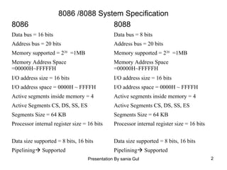
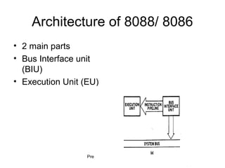
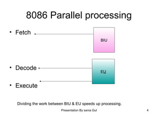
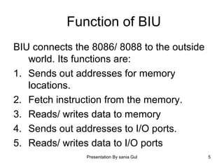
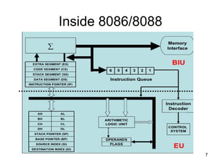
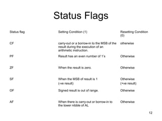
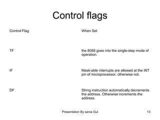
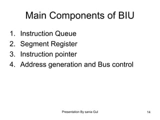
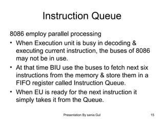
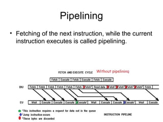
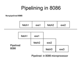
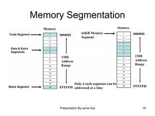
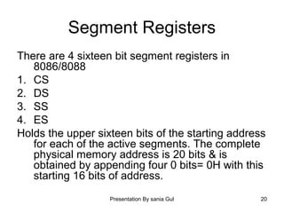
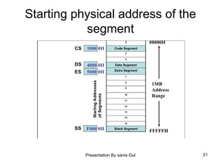
The document discusses the architecture of the 8086/8088 microprocessors. It describes their data buses, address buses, memory support, and segment registers. The 8086 has a 16-bit data bus and 20-bit address bus, while the 8088 has an 8-bit data bus but the same 20-bit address bus. Both support up to 1MB of memory divided into segments of 64KB each. The 8086/8088 use a bus interface unit to access memory and I/O, and an execution unit to decode and execute instructions. They employ pipelining to improve performance by fetching the next instruction in parallel with executing the current one.