COMPUTER ORGANIZATION &
ARCHITECTURE
(BCS-DS-402)
1.3RTL interpretation of instructions,
instruction set.
Ms. Swati Hans,
Assistant Professor
Department of Computer Science &
Engineering- SPL
School of Engineering & Technology
Manav Rachna International Institute of
Research and Studies (Deemed to be
University), Faridabad
2.
Register Transfer language
Digital systems are composed of modules that are constructed from
digital components, such as registers, decoders, arithmetic elements,
and control logic
The modules are interconnected with common data and control paths
to form a digital computer system
The operations executed on data stored in registers are called
microoperations
A microoperation is an elementary operation performed on the
information stored in one or more registers
Examples are shift, count, clear, and load
The internal hardware organization of a digital computer is best by
specifying
The set of registers it contains and their functions
The sequence of microoperations performed on the binary information
stored
The control that initiates the sequence of microoperations
3.
Register Transfer Language(RTL)
It is a low-level language that is used to describe the functioning
of a digital circuit and, more specifically, the transfer of
information between registers. It provides how data moves
from one register to the other and how data is processed within
the digital system. Through RTL, there is a capability of creating
abstraction levels where high-level design descriptions can be
created and easily linked to low-level hardware implementation
in designing, simulating, as well as synthesizing digital circuits
In symbolic notation, it is used to describe the micro-operations
transfer among registers. It is a kind of intermediate
representation that is very close to assembly language, such as
that which is used in a compiler. The term “Register Transfer”
can perform micro-operations and transfer the result of
operation to the same or other register.
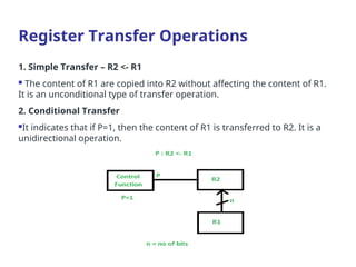
1. Simple Transfer– R2 <- R1
The content of R1 are copied into R2 without affecting the content of R1.
It is an unconditional type of transfer operation.
2. Conditional Transfer
It indicates that if P=1, then the content of R1 is transferred to R2. It is a
unidirectional operation.
Register Transfer Operations
7.
Register Transfer
Datacan move from register to register.
Digital logic used to process data
for example:
Register A Register B
Register C
Digital Logic
Circuits
C A + B
8.
Bus Transfer
Forregister R0 to R3 in a 4 bit system
1 0
3 2
4*1
MUX 3
1 0
3 2
1 0
3 2
4*1
MUX 0
1 0
3 2
1 0
3 2
4*1
MUX 1
1 0
3 2
1 0
3 2
4*1
MUX 2
1 0
3 2
S1 S0 Register selected
0 0 A
0 1 B
1 0 C
1 1 D
S1
S0
4-line
common
bus
Register D Register C Register B Register A
Used for highest bit from each
register
Used for lowest
bit
9.
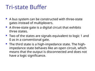
Tri-state Buffer
Abus system can be constructed with three-state
gates instead of multiplexers.
A three-state gate is a digital circuit that exhibits
three states.
Two of the states are signals equivalent to logic 1 and
0 as in a conventional gate.
The third state is a high-impedance state. The high-
impedance state behaves like an open circuit, which
means that the output is disconnected and does not
have a logic significance.
10.
Tri-state buffer gate
Tri-statebuffer gate : Fig. 4-4
When control input =1 : The output is enabled(output
Y = input A)
When control input =0 : The output is disabled(output
Y = high-impedance)
Normal
input A
Control
input C
If C=1, Output Y = A
If C=0, Output = High-impedance
Memory Transfer
Thetransfer of information from a
memory word to the outside
environment is called a read operation
The transfer of new information to be
stored into the memory is called a write
operation
13.
Memory Read andWrite
AR: address register
DR: data register
Read: DR M[AR]
Write: M[AR] R1
14.
Micro-Operations
Operations executedon data stored in registers are called microoperations.
A microoperation is an elementary operation performed on information stored in one or more registers. The result of the operation may
replace the previous binary information of a register or may be transferred to another register.
Types of Micro-operations:
Arithmetic Microoperations
Logical Microoperations
Shift Microoperations
15.
Arithmetic Microoperations
Symbolic designationDescription
R3 ← R1 + R2 Contents of R1 plus R2 transferred to R3
R3 ← R1 – R2 Contents of R1 minus R2 transferred to R3
R2 ← R2 Complement the contents of R2 (1’s complement)
R2 ← R2 + 1 2’s Complement the contents of R2 (negate)
R3 ← R1 + R2 + 1 R1 plus the 2’s complement of R2 (subtract)
R1 ← R1 + 1 Increment the contents of R1 by one
R1 ← R1 – 1 Decrement the contents of R1 by one
Multiplication and division are not basic
arithmetic operations
Multiplication : R0 = R1 * R2
Division : R0 = R1 / R2
16.
Arithmetic Microoperations
Asingle circuit does both arithmetic
addition and subtraction depending on
control signals.
• Arithmetic addition:
R3 R1 + R2 (Here + is not logical OR. It
denotes addition)
17.
Arithmetic Microoperations
Arithmeticsubtraction:
R3 R1 + R2 + 1
where R2 is the 1’s complement of R2.
Adding 1 to the one’s complement is
equivalent to taking the 2’s complement
of R2 and adding it to R1.
18.
BINARY ADDER
Binaryadder is constructed with full-
adder circuits connected in cascade.
19.
BINARY ADDER-SUBTRACTOR
• Theaddition and subtraction operations cane be
combined into one common circuit by including an
exclusive-OR gate with each full-adder.
XOR
M b
0 0 0
0 1 1
1 0 1
1 1 0
20.
BINARY ADDER-SUBTRACTOR
•M = 0: Note that B XOR 0 = B. This is
exactly the same as the binary adder
with carry in C0 = 0.
M = 1: Note that B XOR 1 = B (flip all B bits).
The outputs of the XOR gates are thus the
1’s complement of B.
M = 1 also provides a carry in 1. The entire
operation is: A + B + 1.
4-bit Binary Incrementer
Addsone to a number in a register
Sequential circuit implementation using binary
counter
Combinational circuit implementation using
Half Adder
The least significant HA bit is connected to
logic-1
The output carry from one HA is connected to
the input of the next-higher-order HA
Manipulating thebits stored in a
register
Logic Microoperations
Logic Microoperations
Logic Microoperations
25.
Clear
Logic operationcan…
1) clear a group of bit values (Anding the
bits to be cleared with zeros)
10101101 10101011 R1 (data)
00000000 11111111 R2 (mask)
00000000 10101011 R1
26.
Set
2) set agroup of bit values (Oring the bits to
be set to ones with ones)
10101101 10101011 R1 (data)
11111111 00000000 R2 (mask)
11111111 10101011 R1
27.
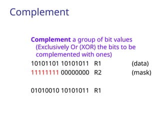
Complement
Complement a groupof bit values
(Exclusively Or (XOR) the bits to be
complemented with ones)
10101101 10101011 R1 (data)
11111111 00000000 R2 (mask)
01010010 10101011 R1
28.
• A varietyof logic gates are
inserted for each bit of
registers. Different bitwise
logical operations are selected
by select signals.
LOGIC CIRCUIT
29.
Shift Microoperations
Shiftexample: 11000
Shift Microoperations :
Shift microoperations are used for serial
transfer of data
Three types of shift microoperation : Logical,
Circular, and Arithmetic
30.
Shift Microoperations
Symbolic designationDescription
R ← shl R Shift-left register R
R ← shr R Shift-right register R
R ← cil R Circular shift-left register R
R ← cir R Circular shift-right register R
R ← ashl R Arithmetic shift-left R
R ← ashr R Arithmetic shift-right R
Shift Microoperations
31.
Logical Shift
A logicalshift transfers 0 through the serial
input
The bit transferred to the end position
through the serial input is assumed to be 0
during a logical shift (Zero inserted)
32.
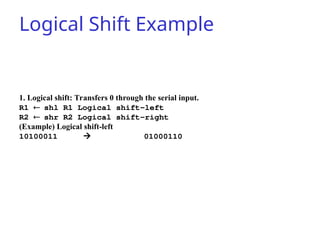
Logical Shift Example
1.Logical shift: Transfers 0 through the serial input.
R1 shl R1 Logical shift-left
R2 shr R2 Logical shift-right
(Example) Logical shift-left
10100011 01000110
33.
Circular Shift
The circularshift circulates the bits of the
register around the two ends without loss of
information
Arithmetic Shift
An arithmeticshift shifts a signed binary
number to the left or right
An arithmetic shift-left multiplies a signed
binary number by 2
An arithmetic shift-right divides the number by
2
In arithmetic shifts the sign bit receives a
special treatment
36.
Arithmetic Shift Right
Arithmetic right-shift: Rn-1 remains unchanged;
Rn-2 receives Rn-1, Rn-3 receives Rn-2, so on.
For a negative number, 1 is shifted from the sign bit
to the right. The sign bit remained unchanged.
37.
Arithmetic Shift Right
Arithmetic Shift Right :
Example 1
0100 (4)
0010 (2)
Example 2
1010 (-6)
1101 (-3)
38.
Arithmetic Shift Left
Theoperation is same with Logic shift-left
In this shift, each bit is moved to the left one by one. The empty least
significant bit (LSB) is filled with zero and the most significant bit
(MSB) is rejected. Same as the Left Logical Shift.
39.
Instruction Set Architecture(ISA)
ISA serves as an interface between hardware and software.
•It defines set of instructions that a processor can execute & how they are
encoded.
•ISA impacts the performance, power consumption, and software
compatibility of a processor.
Instruction Set Architecture (ISA)
•CISC
•RISC
40.
Evolution of CISCand RISC
Architectures
• CISC (Complex Instruction Set Computer): Developed in the 1970s,
CISC aimed to reduce the number of instructions needed per program,
often including complex instructions that could perform multiple
operations.
• RISC (Reduced Instruction Set Computer): Introduced in the 1980s,
RISC focused on simplifying the instruction set by using a smaller set of
simple and efficient instructions, with the goal of improving
performance by executing instructions faster.
41.
CISC (Complex InstructionSet Computer)
CISC is a computer architecture that emphasizes a large and complex
instruction set. CISC processors have many instructions that can
perform multiple operations in a single instruction. It is used in PCs,
desktop computers, laptops, Workstations.
Goal of CISC architecture
To reduce the number of instructions a program needs to execute, which can lead
to faster program execution. i.e. CISC tries to minimize the number of
instructions per program but at the cost of increasing the number of cycles
per instruction.
CISC processors typically have more extensive hardware support for performing
complex instructions. This allows for more sophisticated operations to be
performed in a single instruction which can lead to faster program execution.
However, increased complexity can also lead to slower processing times.
42.
CISC Characteristics:
• CISCsupports a set of a large number of instructions (typically from 100 to 250
instructions).
• CISC has some instructions which perform specialized tasks and are used
infrequently.
• CISC has a large variety of addressing modes (typically from 5 to 20 different
modes).
• CISC can have variable-length instruction formats.
• CISC instructions occupy more than one word in memory.
• It has instructions that manipulate operands in memory.
• Uses fewer registers.
• Uses Microprogrammed control.
• Complex hardware required.
• Less pipelining.
• CISC may take multiple clock cycles to execute the instruction.
• CISC handles a wide range of data types.
43.
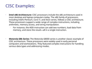
CISC Examples:
• Intelx86 Architecture: CISC processors include the x86 architecture used in
most desktop and laptop computers today. The x86 family of processors,
including Intel’s Pentium, Core i7, and Xeon series, follows a CISC architecture.
These processors support a wide range of complex instructions, including
arithmetic, memory access, and string manipulation.
• For instance, the ADD instruction can add two numbers, load data from
memory, and store the result—all in a single instruction.
• Motorola 68k Series: The Motorola 68000 series is another classic example of
CISC architecture. These processors were widely used in early personal
computers and workstations. They featured complex instructions for handling
various data types and addressing modes.
44.
CISC
Advantages ofCISC:
• Ability to perform complex instructions
• Programs require fewer instructions to execute
• Greater hardware support for performing complex instructions.
Disadvantages of CISC:
• Increased complexity can lead to slower processing times
• Larger chip size can lead to increased costs
45.
RISC (Reduced InstructionSet
Computer)
• RISC is a computer architecture that emphasizes a simple and efficient
instruction set.
RISC processors have a smaller instruction set than CISC processors,
with each instruction performing a single operation.
• RISC used in smartphones, tablets, and embedded systems,
routers, TV setup boxes.
Goal of RISC architecture:
To reduce the amount of work the processor needs to do for each
instruction, which leads to faster and more efficient processing. i.e.
• RISC reduces the cycles per instruction at the cost of the number of
instructions per program.
• RISC processors often use pipelining to achieve greater performance.
46.
RISC Characteristics
•A RISCprocessor has a relatively few instructions.
•RISC processor has a relatively few addressing modes.
•In the RISC processor, all operations are performed within the
registers of the CPU.
•Memory access is limited to LOAD and STORE instructions.
•RISC has fixed-length instruction format.
•RISC instructions fit within a single word.
•RISC can be hardwired control rather than micro-programmed
control.
•Simple hardware required, consumes less power and has high
performance.
•RISC has single-cycle instruction execution.
•RISC has easily decodable instruction format.
•Uses more registers.
•Highly pipelined.
•RISC supports fewer data types.
47.
RISC Examples
RISCprocessors include the ARM, MIPS, and PowerPC
architectures.
• ARM (Advanced RISC Machines) architecture is used in many
smartphones, tablets, and embedded systems.
• MIPS (Microprocessor without Interlocked Pipeline Stages)
architecture is commonly used in embedded systems such as
routers and TV set-top boxes.
MIPS processors are RISC-based.
• PowerPC architecture was used in Apple's Power Macintosh
computers before they switched to Intel processors.
48.
RISC
Advantages ofRISC:
• Simplified instruction set leads to faster processing.
• Pipelining can increase performance.
• Lower power consumption.
• Smaller chip size, which can lead to cost savings.
Disadvantages of RISC:
• Programs may require more instructions to complete a task than with
CISC.
• Limited ability to perform complex instructions.


![Memory Read and Write
AR: address register
DR: data register
Read: DR M[AR]
Write: M[AR] R1](https://image.slidesharecdn.com/1-250225180301-3ddb098a/85/RTL-Instruction-set-_-13-320.jpg)