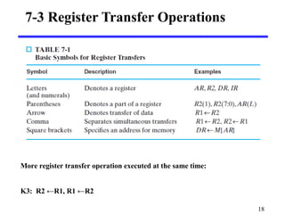
The document discusses processor logic design and register transfer logic. It describes registers, their functions, and how data is transferred between registers. There are four categories of microoperations - interregister transfer, arithmetic, logic, and shift. Interregister transfer moves data between registers without changing it. Arithmetic operations perform math on register data. Logic operations perform AND, OR, etc on register bit values. Shift operations serially move data within a register. The document also discusses conditional control statements that allow different microoperations to be selected based on register values.
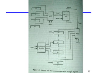
Pipelining is an speed up technique where multiple instructions are overlapped in execution on a processor. It is an important topic in Computer Architecture.
This slide try to relate the problem with real life scenario for easily understanding the concept and show the major inner mechanism.
Pipelining is an speed up technique where multiple instructions are overlapped in execution on a processor. It is an important topic in Computer Architecture.
This slide try to relate the problem with real life scenario for easily understanding the concept and show the major inner mechanism.
This presentation gives the details about the data types available in Embedded C. It also discusses the pros and cons of writing codes in C for 8051. Different example codes are considered.
Programmable Peripheral Interface (PPI) 8255
Features of 8255
Block Diagram of 8255 PPI
3 Modes of operation of 8255 PPI
BSR Mode of 8255 PPI
Parallel IO of 8255 PPI
IC 8155/8156
Features of 8155/8156
Block Diagram of 8155/8156
Chip Enable Logic & Port Addresses (Peripheral I/O Addressing
Scheme
Control Word Register of 8155
Timers of 8155/8156
Modes of Timers of 8155
IC 8355/8755
Block Diagram of 8155/8156
This method of checking the signal in the system for processing is called Polling Method. In this method, the problem is that the processor has to waste number of clock cycles just for checking the signal in the system, by this processor will become busy unnecessarily. If any signal came for the process, processor will take some time to process the signal due to the polling process in action. So system performance also will be degraded and response time of the system will also decrease.
Designing of 8 BIT Arithmetic and Logical Unit and implementing on Xilinx Ver...Rahul Borthakur
The main objective of this project was to design and verify different operations of Arithmetic and Logical Unit (ALU). To implement ALU, the coding was written in VHDL (VHSIC Hardware Description Language) and verified in ModelSim. The device was configured and using FPGA (Field-programmable gate array) verification, debugging was done.
• Register Transfer Language
• Register Transfer
• Bus and Memory Transfers
• Arithmetic Microoperations
• Logic Microoperations
• Shift Microoperations
• Arithmetic Logic Shift Unit
unit1COA Computer Organisation and Architecture
BTECH
CSE
IT
AIML
unit1COA Computer Organisation and Architectureunit1COA Computer Organisation and Architecture
Register transfer and microoperations part 1Prasenjit Dey
Register transfer language, hardware implementation of bus transfer using multiplexer and three state buffer, hardware implementation of memory transfer e.g., memory read and memory write.
How to Split Bills in the Odoo 17 POS ModuleCeline George
Bills have a main role in point of sale procedure. It will help to track sales, handling payments and giving receipts to customers. Bill splitting also has an important role in POS. For example, If some friends come together for dinner and if they want to divide the bill then it is possible by POS bill splitting. This slide will show how to split bills in odoo 17 POS.
Students, digital devices and success - Andreas Schleicher - 27 May 2024..pptxEduSkills OECD
Andreas Schleicher presents at the OECD webinar ‘Digital devices in schools: detrimental distraction or secret to success?’ on 27 May 2024. The presentation was based on findings from PISA 2022 results and the webinar helped launch the PISA in Focus ‘Managing screen time: How to protect and equip students against distraction’ https://www.oecd-ilibrary.org/education/managing-screen-time_7c225af4-en and the OECD Education Policy Perspective ‘Students, digital devices and success’ can be found here - https://oe.cd/il/5yV
Palestine last event orientationfvgnh .pptxRaedMohamed3
An EFL lesson about the current events in Palestine. It is intended to be for intermediate students who wish to increase their listening skills through a short lesson in power point.
Operation “Blue Star” is the only event in the history of Independent India where the state went into war with its own people. Even after about 40 years it is not clear if it was culmination of states anger over people of the region, a political game of power or start of dictatorial chapter in the democratic setup.
The people of Punjab felt alienated from main stream due to denial of their just demands during a long democratic struggle since independence. As it happen all over the word, it led to militant struggle with great loss of lives of military, police and civilian personnel. Killing of Indira Gandhi and massacre of innocent Sikhs in Delhi and other India cities was also associated with this movement.
Model Attribute Check Company Auto PropertyCeline George
In Odoo, the multi-company feature allows you to manage multiple companies within a single Odoo database instance. Each company can have its own configurations while still sharing common resources such as products, customers, and suppliers.
Ethnobotany and Ethnopharmacology:
Ethnobotany in herbal drug evaluation,
Impact of Ethnobotany in traditional medicine,
New development in herbals,
Bio-prospecting tools for drug discovery,
Role of Ethnopharmacology in drug evaluation,
Reverse Pharmacology.
The French Revolution, which began in 1789, was a period of radical social and political upheaval in France. It marked the decline of absolute monarchies, the rise of secular and democratic republics, and the eventual rise of Napoleon Bonaparte. This revolutionary period is crucial in understanding the transition from feudalism to modernity in Europe.
For more information, visit-www.vavaclasses.com
Instructions for Submissions thorugh G- Classroom.pptxJheel Barad
This presentation provides a briefing on how to upload submissions and documents in Google Classroom. It was prepared as part of an orientation for new Sainik School in-service teacher trainees. As a training officer, my goal is to ensure that you are comfortable and proficient with this essential tool for managing assignments and fostering student engagement.
2. Contents
• Register Transfer Logic
Inter Register Transfer
Arithmetic Microoperations
Logic Microoperations
Shift Microoperations
• Conditional Control Statements
2
3. 3
Registers
Register
• a collection of binary storage elements
• included a set of flip-flop
• n-bit register store n-bit binary information
Frequently used to perform simple data
storage and data movement and processing
operations
5. 5
Register transfer
Large digital systems are often designed by modular,
hierarchical approach
Large digital systems are partitioned into two types of modules
• Data path: performs data-processing operations
• Control unit: determine the sequence of those operations
6. 6
Register transfer
The registers are assumed to be basic components of the
digital system
Register transfer operation: movement on the data stored
in register and the processing performed on the data
The basic components for describing a digital system in
register transfer logic is:
• The set of registers in digital systems and their
functions.
• The operations performed on the data
• Control on the sequence of operations
7. Register transfer Operations
Microoperations: operations executed on data stored in one
or more registers.
For any function of the computer, a sequence of
micro operations is used to describe it
The result of the operation may be:
• replace the previous binary information of a register or
• transferred to another register
7
8. Register Transfer Language
Register Transfer Language (RTL) : a symbolic notation to
describe the microoperation transfers among registers
Next steps:
• Define symbols for various types of microoperations,
• Describe the hardware that implements these
microoperations
A statement in a register transfer language consists of a
control function and a list of micro operations.
8
9. The type of microoperations in digital systems can be
classified into four categories:
• Interregister –transfer microoperations do not change the
information content when the binary information moves from one
register to another.
• Arithmetic micro operations perform arithmetic on numbers stored
in registers.
• Logic microoperations perform operations such as AND and OR on
individual pairs of bits stored in registers.
• Shift microopeartions specify operations for shift registers.
9
10. 10
InterRegister Transfer
Computer registers are designated by capital letters
(sometimes followed by numerals) to denote the function
of the register
R1: processor register
MAR: Memory Address Register (holds an address
for a memory unit)
PC: Program Counter
IR: Instruction Register
SR: Status Register
11. The individual flip-flops in an n-bit register are numbered
in sequence from 0 to n-1 (from the right position toward
the left position)
11
R1
Register R1
7 6 5 4 3 2 1 0
Showing individual bits
A block diagram of a register
13. 13
Information transfer from one register to another is described
by a replacement operator: R2 ← R1
This statement denotes a transfer of the content of register R1
into register R2
The transfer happens in one clock cycle
The content of the R1 (source) does not change
The content of the R2 (destination) will be lost and replaced by
the new data transferred from R1
We are assuming that the circuits are available from the outputs
of the source register to the inputs of the destination register,
and that the destination register has a parallel load capability
14. 14
The condition which determines when the transfer is to occur
is called a control function.
Conditional transfer occurs only under a control condition
Representation of a (conditional) transfer
P: R2 ← R1
A binary condition (P equals to 0 or 1) determines when the
transfer occurs
The content of R1 is transferred into R2 only if P is 1
16. The control function is included with the statement is as
follows:
x’T1: A ← B
The control function is terminated with a colon.
It shows that the transfer operation be executed by the
hardware only when the Boolean function x’T1 = 1
• i.e,when variable x=0 and timing variable T1 = 1
16
21. Bus and Memory Transfers
Paths must be provided to transfer information from one register
to another
A Common Bus System is a scheme for transferring information
between registers in a multiple-register configuration
A bus: set of common lines, one for each bit of a register,
through which binary information is transferred one at a time
Control signals determine which register is selected by the bus
during each particular register transfer
21
25. Memory Transfer
Memory read : Transfer from memory
Memory write : Transfer to memory
Data being read or wrote is called a memory word (called
M)
It is necessary to specify the address of M when writing
/reading memory
This is done by enclosing the address in square brackets
following the letter M
Example: M[0016] : the memory contents at address
0x0016
25
27. Assume that the address of a memory unit is
stored in a register called the Address
Register AR
Lets represent a Data Register with DR,
then:
Read: DR ← M[AR]
Write: M[AR] ← DR
27
29. The transfer of information from a bus into one of many
destination registers is done:
• By connecting the bus lines to the inputs of all
destination registers and then:
• activating the load control of the particular destination
register selected
We write: R2 ← C to symbolize that the content of register
C is loaded into the register R2 using the common system
bus
It is equivalent to: BUS ←C, (select C)
R2 ←BUS (Load R2)
29
35. Logic microoperations
Logic microoperations specify binary operations for a
string of bits stored in registers.
These operations consider each bit in the registers
seperately and treat it as a binary variable.
Exclusive –OR operation symbolized by the statement:
F ← A ⊕ B
If the contents of register A is 1010 and B is 1100, the
information transferred to register F is 0110:
1010 content of A
1100 content of B
0110 content of F ← A ⊕ B
35
36. 16 different possible logic operations that
can be performed with two binary variables,
The symbol ∨ will be used to denote OR
microoperation and the symbol ∧ to denote
an AND microoperation.
Complement microoperation is the sameas
1’s complement and use a bar on top of the
letter that denotes the register.
36
38. Shift Microoperations
Used for serial transfer of data
Also used in conjunction with arithmetic, logic, and other
data-processing operations
The contents of the register can be shifted to the left or to
the right
As being shifted, the first flip-flop receives its binary
information from the serial input
Three types of shift: Logical, Circular, and Arithmetic
38
46. CONDITIONAL CONTROL STATEMENTS
Conditional control statement is symbolized by an if-then –
else statement as follows:
P: If (condition) then [microoperation(s)] else
[microoperation(s)]
• It means that if the control condition stated within the
parentheses after the word if is true, then the
microoperation enclosed within the parentheses after
the word then is executed.
• If the condition is not true, the microoperation listed
after the word else is executed.
• In any case the control function P must occur for
anything to be done.
46
47. Eg:
T2: If(C=0) then (F ← 1) else (F ← 0)
F is assumed to be a 1-bit register(flip-flop) that can be set
or cleared.
If register C is a 1-bit register, the statement is equivalent
to the following two statements:
C’T2: F ←1
CT2: F ←0
• Only one of the microoperation will be executed during T2,
depending on the value of C
47
Editor's Notes
States: 22 = 4
Input Combinations: 22 = 4
Output Combinations: 22 = 4
Y = A
A(t+1) = IN
Moore
States = 2n
Input Combinations = 2n
Output Combinations = 2n