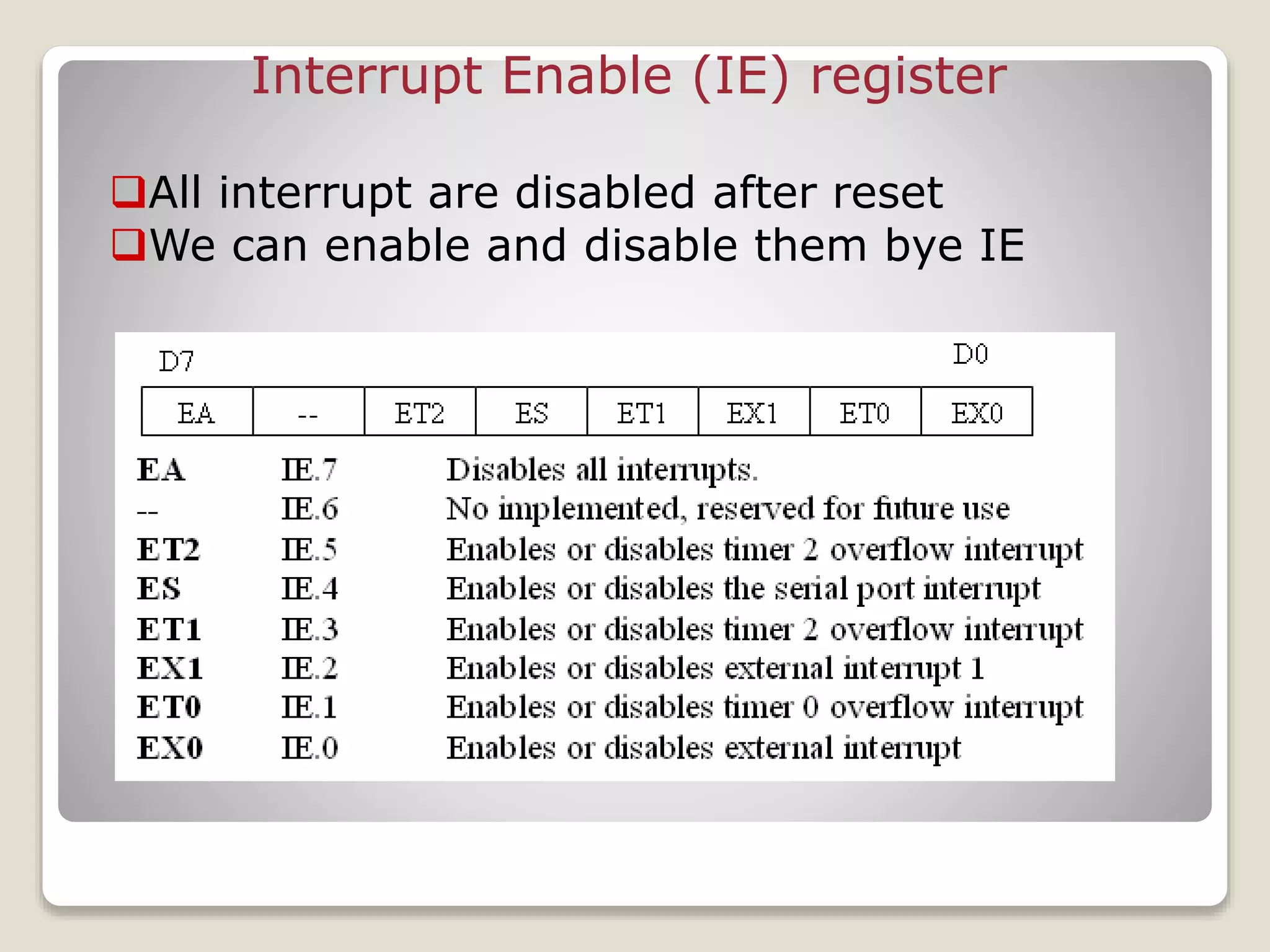
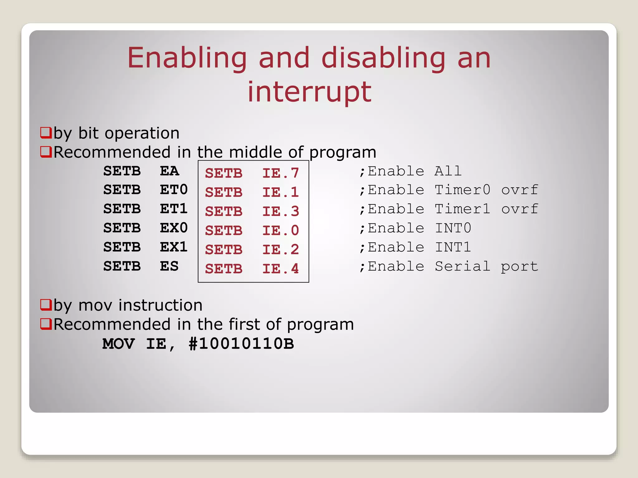
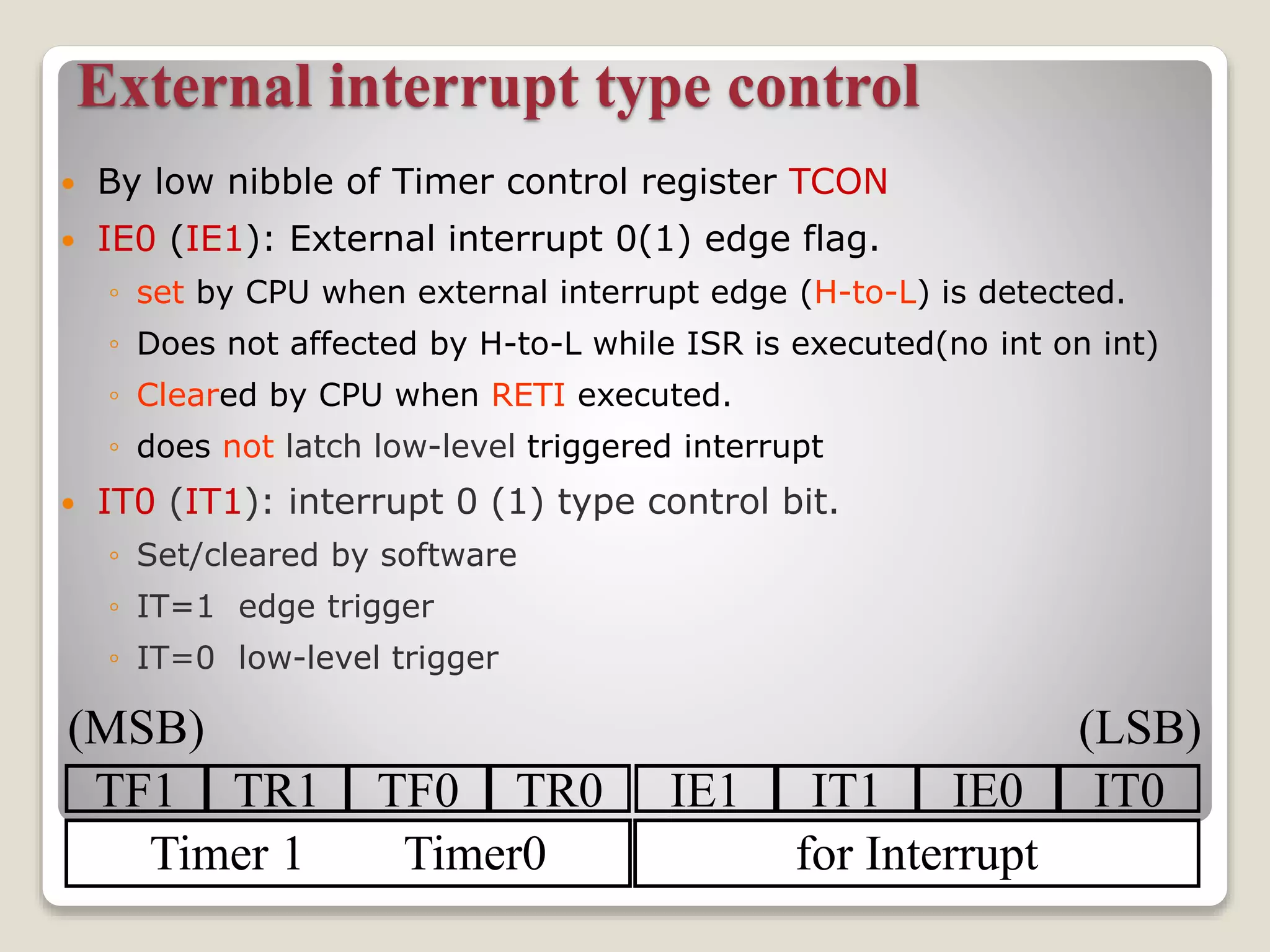
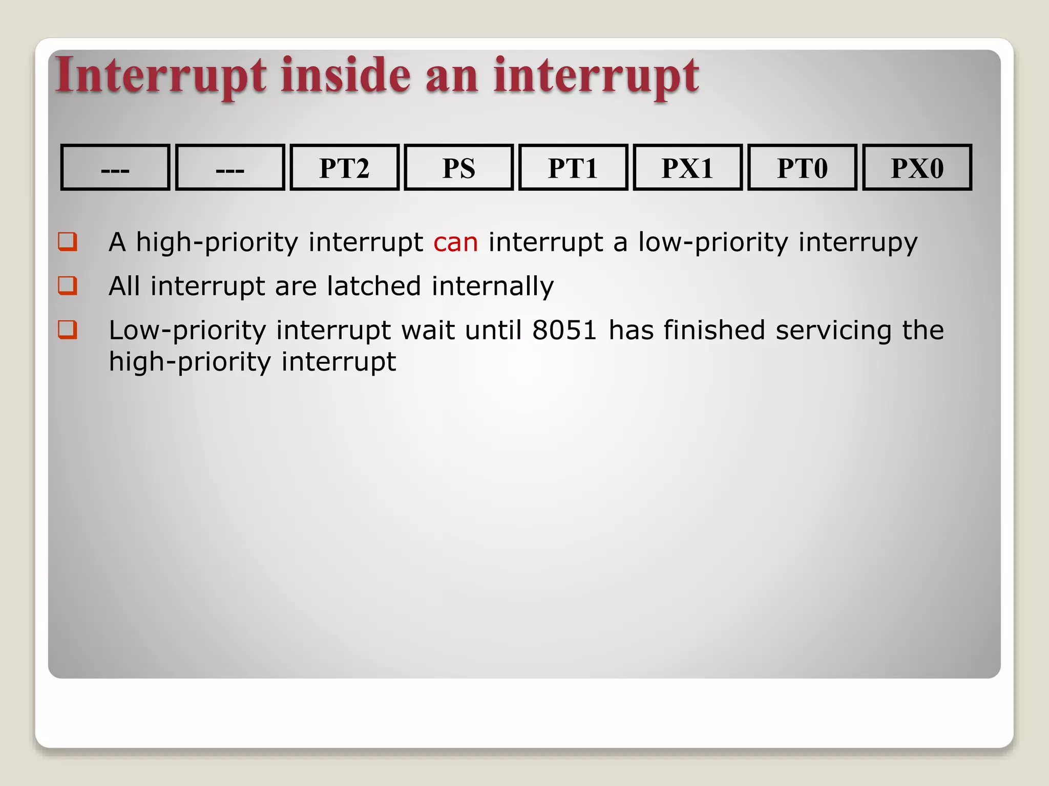
Microcontroller 8051
Interrupts
Present by:
LAXMI INSTITUTION OF
TECHNOLOGY
Sr. no. Name Enrollment No.
1 Kulkarni Ajay 150863109004
2 Nakum Dharmesh M. 150863109005
3 Nayakvade Ragini B. 150863109006
4 Parmar Ashish V. 150863109007
Sub: MMCI
2150907
Interrupts Programming
 An interrupt is an external or internal event that interrupts the
microcontroller to inform it that a device needs its service.
Interrupts vs. Polling
 A single microcontroller can serve several devices.
 There are two ways to do that:
◦ interrupts
◦ polling.
 The program which is associated with the interrupt is called
the interrupt service routine (ISR) or interrupt handler.
Interrupts vs. Polling
 An interrupt is an external or internal event that
interrupts the microcontroller
◦ To inform it that a device needs its service
 A single microcontroller can serve several devices by
two ways
◦ Interrupts
 Whenever any device needs its service, the device notifies the
microcontroller by sending it an interrupt signal
 Upon receiving an interrupt signal, the microcontroller
interrupts whatever it is doing and serves the device
Interrupts vs. Polling (cont.)
◦ The program which is associated with the interrupt is
called the interrupt service routine (ISR) or interrupt
handler
◦ Polling
 The microcontroller continuously monitors the
status of a given device
◦ ex. JNB TF, target
 When the conditions met, it performs the service
 After that, it moves on to monitor the next device
until every one is serviced
◦ Polling can monitor the status of several devices and
serve each of them as certain conditions are met
 The polling method is not efficient, since it wastes
much of the microcontroller’s time by polling
devices that do not need service
Interrupts vs. Polling (cont.)
 The advantage of interrupts is:
◦ The microcontroller can serve many devices (not all at
the same time)
 Each device can get the attention of the microcontroller
based on the assigned priority
 For the polling method, it is not possible to assign
priority since it checks all devices in a round-robin
fashion
◦ The microcontroller can also ignore (mask) a device
request for service
 This is not possible for the polling method
Steps in executing an interrupt
 Finish current instruction and saves the PC on stack.
 Jumps to a fixed location in memory depend on type of
interrupt
 Starts to execute the interrupt service routine until RETI
(return from interrupt)
 Upon executing the RETI the microcontroller returns to the
place where it was interrupted. Get pop PC from stack
Interrupt Sources
 Original 8051 has 6 sources of
interrupts
◦ Reset
◦ Timer 0 overflow
◦ Timer 1 overflow
◦ External Interrupt 0
◦ External Interrupt 1
◦ Serial Port events (buffer full, buffer empty, etc)
 Enhanced version has 22 sources
◦ More timers, programmable counter array, ADC, more
external interrupts, another serial port (UART)
Interrupt Vectors
Each interrupt has a specific place in code memory
where program execution (interrupt service routine)
begins.
External Interrupt 0: 0003h
Timer 0 overflow: 000Bh
External Interrupt 1: 0013h
Timer 1 overflow: 001Bh
Serial : 0023h
Timer 2 overflow(8052+) 002bh
Note: that there are
only 8 memory
locations between
vectors.
SJMP main
ORG 03H
ljmp int0sr
ORG 0BH
ljmp t0sr
ORG 13H
ljmp int1sr
ORG 1BH
ljmp t1sr
ORG 23H
ljmp serialsr
ORG 30H
main:
…
END
ISRs and Main Program in
8051
Interrupt Enable (IE) register
All interrupt are disabled after reset
We can enable and disable them bye IE
Enabling and disabling an
interrupt
by bit operation
Recommended in the middle of program
SETB EA ;Enable All
SETB ET0 ;Enable Timer0 ovrf
SETB ET1 ;Enable Timer1 ovrf
SETB EX0 ;Enable INT0
SETB EX1 ;Enable INT1
SETB ES ;Enable Serial port
by mov instruction
Recommended in the first of program
MOV IE, #10010110B
SETB IE.7
SETB IE.1
SETB IE.3
SETB IE.0
SETB IE.2
SETB IE.4
Timer ISR
 Notice that
◦ There is no need for a “CLR TFx” instruction in
timer ISR
◦ 8051 clears the TF internally upon jumping to
ISR
 Notice that
◦ We must reload timer in mode 1
◦ There is no need on mode 2 (timer auto
reload)
External interrupt type control
 By low nibble of Timer control register TCON
 IE0 (IE1): External interrupt 0(1) edge flag.
◦ set by CPU when external interrupt edge (H-to-L) is detected.
◦ Does not affected by H-to-L while ISR is executed(no int on int)
◦ Cleared by CPU when RETI executed.
◦ does not latch low-level triggered interrupt
 IT0 (IT1): interrupt 0 (1) type control bit.
◦ Set/cleared by software
◦ IT=1 edge trigger
◦ IT=0 low-level trigger
TF1 TR1 TF0 TR0 IE1 IT1 IE0 IT0
Timer 1 Timer0 for Interrupt
(MSB) (LSB)
External Interrupts
IE0 (TCON.3)
0003
INT0
(Pin 3.2) 0
1
2
IT0
Edge-triggered
Level-triggered (default)
IE1 (TCON.3)
INT0
(Pin 3.3) 0
1
2
IT1
Edge-triggered
Level-triggered (default)
0013
Interrupt Priorities
 What if two interrupt sources interrupt at the same
time?
 The interrupt with the highest PRIORITY gets
serviced first.
 All interrupts have a power on default priority order.
1. External interrupt 0 (INT0)
2. Timer interrupt0 (TF0)
3. External interrupt 1 (INT1)
4. Timer interrupt1 (TF1)
5. Serial communication (RI+TI)
 Priority can also be set to “high” or “low” by IP reg.
Interrupt Priorities (IP) Register
IP.7: reserved
IP.6: reserved
IP.5: timer 2 interrupt priority bit(8052 only)
IP.4: serial port interrupt priority bit
IP.3: timer 1 interrupt priority bit
IP.2: external interrupt 1 priority bit
IP.1: timer 0 interrupt priority bit
IP.0: external interrupt 0 priority bit
--- PX0PT0PX1PT1PSPT2---
Interrupt Priorities Example
 MOV IP , #00000100B or SETB IP.2 gives priority order
1. Int1
2. Int0
3. Timer0
4. Timer1
5. Serial
 MOV IP , #00001100B gives priority order
1. Int1
2. Timer1
3. Int0
4. Timer0
5. Serial
--- PX0PT0PX1PT1PSPT2---
Interrupt inside an interrupt
--- PX0PT0PX1PT1PSPT2---
 A high-priority interrupt can interrupt a low-priority interrupy
 All interrupt are latched internally
 Low-priority interrupt wait until 8051 has finished servicing the
high-priority interrupt
The End

Micro controller 8051 Interrupts

  • 1.
    Microcontroller 8051 Interrupts Present by: LAXMIINSTITUTION OF TECHNOLOGY Sr. no. Name Enrollment No. 1 Kulkarni Ajay 150863109004 2 Nakum Dharmesh M. 150863109005 3 Nayakvade Ragini B. 150863109006 4 Parmar Ashish V. 150863109007 Sub: MMCI 2150907
  • 2.
    Interrupts Programming  Aninterrupt is an external or internal event that interrupts the microcontroller to inform it that a device needs its service. Interrupts vs. Polling  A single microcontroller can serve several devices.  There are two ways to do that: ◦ interrupts ◦ polling.  The program which is associated with the interrupt is called the interrupt service routine (ISR) or interrupt handler.
  • 3.
    Interrupts vs. Polling An interrupt is an external or internal event that interrupts the microcontroller ◦ To inform it that a device needs its service  A single microcontroller can serve several devices by two ways ◦ Interrupts  Whenever any device needs its service, the device notifies the microcontroller by sending it an interrupt signal  Upon receiving an interrupt signal, the microcontroller interrupts whatever it is doing and serves the device
  • 4.
    Interrupts vs. Polling(cont.) ◦ The program which is associated with the interrupt is called the interrupt service routine (ISR) or interrupt handler ◦ Polling  The microcontroller continuously monitors the status of a given device ◦ ex. JNB TF, target  When the conditions met, it performs the service  After that, it moves on to monitor the next device until every one is serviced ◦ Polling can monitor the status of several devices and serve each of them as certain conditions are met  The polling method is not efficient, since it wastes much of the microcontroller’s time by polling devices that do not need service
  • 5.
    Interrupts vs. Polling(cont.)  The advantage of interrupts is: ◦ The microcontroller can serve many devices (not all at the same time)  Each device can get the attention of the microcontroller based on the assigned priority  For the polling method, it is not possible to assign priority since it checks all devices in a round-robin fashion ◦ The microcontroller can also ignore (mask) a device request for service  This is not possible for the polling method
  • 6.
    Steps in executingan interrupt  Finish current instruction and saves the PC on stack.  Jumps to a fixed location in memory depend on type of interrupt  Starts to execute the interrupt service routine until RETI (return from interrupt)  Upon executing the RETI the microcontroller returns to the place where it was interrupted. Get pop PC from stack
  • 7.
    Interrupt Sources  Original8051 has 6 sources of interrupts ◦ Reset ◦ Timer 0 overflow ◦ Timer 1 overflow ◦ External Interrupt 0 ◦ External Interrupt 1 ◦ Serial Port events (buffer full, buffer empty, etc)  Enhanced version has 22 sources ◦ More timers, programmable counter array, ADC, more external interrupts, another serial port (UART)
  • 8.
    Interrupt Vectors Each interrupthas a specific place in code memory where program execution (interrupt service routine) begins. External Interrupt 0: 0003h Timer 0 overflow: 000Bh External Interrupt 1: 0013h Timer 1 overflow: 001Bh Serial : 0023h Timer 2 overflow(8052+) 002bh Note: that there are only 8 memory locations between vectors.
  • 9.
    SJMP main ORG 03H ljmpint0sr ORG 0BH ljmp t0sr ORG 13H ljmp int1sr ORG 1BH ljmp t1sr ORG 23H ljmp serialsr ORG 30H main: … END ISRs and Main Program in 8051
  • 10.
    Interrupt Enable (IE)register All interrupt are disabled after reset We can enable and disable them bye IE
  • 11.
    Enabling and disablingan interrupt by bit operation Recommended in the middle of program SETB EA ;Enable All SETB ET0 ;Enable Timer0 ovrf SETB ET1 ;Enable Timer1 ovrf SETB EX0 ;Enable INT0 SETB EX1 ;Enable INT1 SETB ES ;Enable Serial port by mov instruction Recommended in the first of program MOV IE, #10010110B SETB IE.7 SETB IE.1 SETB IE.3 SETB IE.0 SETB IE.2 SETB IE.4
  • 12.
    Timer ISR  Noticethat ◦ There is no need for a “CLR TFx” instruction in timer ISR ◦ 8051 clears the TF internally upon jumping to ISR  Notice that ◦ We must reload timer in mode 1 ◦ There is no need on mode 2 (timer auto reload)
  • 13.
    External interrupt typecontrol  By low nibble of Timer control register TCON  IE0 (IE1): External interrupt 0(1) edge flag. ◦ set by CPU when external interrupt edge (H-to-L) is detected. ◦ Does not affected by H-to-L while ISR is executed(no int on int) ◦ Cleared by CPU when RETI executed. ◦ does not latch low-level triggered interrupt  IT0 (IT1): interrupt 0 (1) type control bit. ◦ Set/cleared by software ◦ IT=1 edge trigger ◦ IT=0 low-level trigger TF1 TR1 TF0 TR0 IE1 IT1 IE0 IT0 Timer 1 Timer0 for Interrupt (MSB) (LSB)
  • 14.
    External Interrupts IE0 (TCON.3) 0003 INT0 (Pin3.2) 0 1 2 IT0 Edge-triggered Level-triggered (default) IE1 (TCON.3) INT0 (Pin 3.3) 0 1 2 IT1 Edge-triggered Level-triggered (default) 0013
  • 15.
    Interrupt Priorities  Whatif two interrupt sources interrupt at the same time?  The interrupt with the highest PRIORITY gets serviced first.  All interrupts have a power on default priority order. 1. External interrupt 0 (INT0) 2. Timer interrupt0 (TF0) 3. External interrupt 1 (INT1) 4. Timer interrupt1 (TF1) 5. Serial communication (RI+TI)  Priority can also be set to “high” or “low” by IP reg.
  • 16.
    Interrupt Priorities (IP)Register IP.7: reserved IP.6: reserved IP.5: timer 2 interrupt priority bit(8052 only) IP.4: serial port interrupt priority bit IP.3: timer 1 interrupt priority bit IP.2: external interrupt 1 priority bit IP.1: timer 0 interrupt priority bit IP.0: external interrupt 0 priority bit --- PX0PT0PX1PT1PSPT2---
  • 17.
    Interrupt Priorities Example MOV IP , #00000100B or SETB IP.2 gives priority order 1. Int1 2. Int0 3. Timer0 4. Timer1 5. Serial  MOV IP , #00001100B gives priority order 1. Int1 2. Timer1 3. Int0 4. Timer0 5. Serial --- PX0PT0PX1PT1PSPT2---
  • 18.
    Interrupt inside aninterrupt --- PX0PT0PX1PT1PSPT2---  A high-priority interrupt can interrupt a low-priority interrupy  All interrupt are latched internally  Low-priority interrupt wait until 8051 has finished servicing the high-priority interrupt
  • 19.