Downloaded 687 times

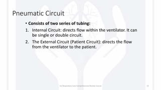
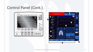
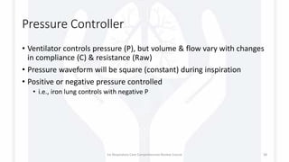
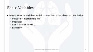
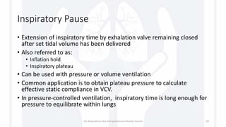
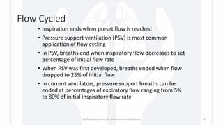
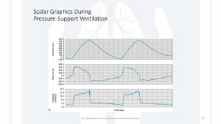
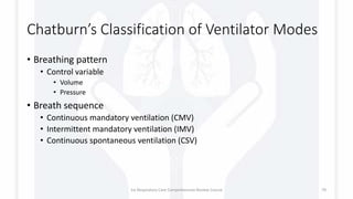
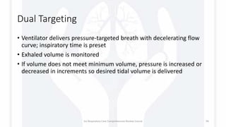
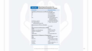
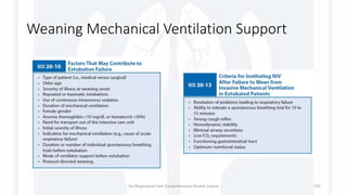
![Components of a Ventilator
Those components are:
• User interface
• Breath Delivery [Patient]
Unit
• Backup power supply
[Rechargeable batteries]
• Air compressor.
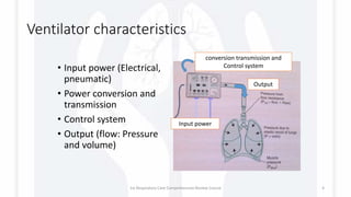
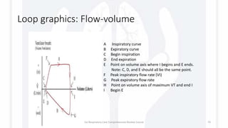
Physical characteristics
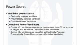
Ventilator power source
• Electrically powered ventilator
• Pneumatically powered ventilator
• Combined Power Ventilators
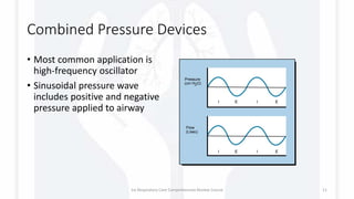
Positive or negative pressure
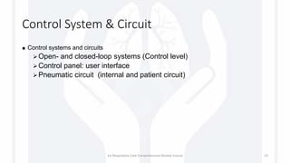
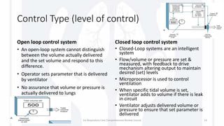
Control systems and circuits
Open- and closed-loop systems
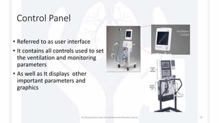
Control panel: user interface
Pneumatic circuit (internal and
patient circuit)
Drive mechanism
Compressor or Blowers
displacement
Flow control valves
Output
Pressure, volumes, and flow
scalars
1st Respiratory Care Comprehensive Review Course 5](https://image.slidesharecdn.com/rccrcmechanicalventilation1-170829075318/85/Mechanical-Ventilation-101-5-320.jpg)
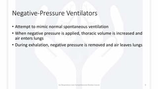

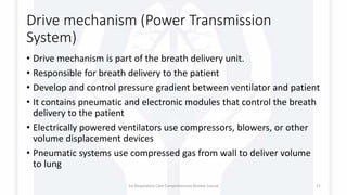


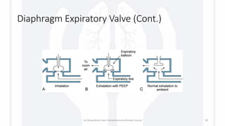
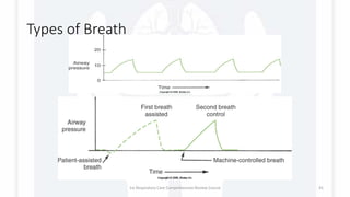
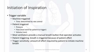
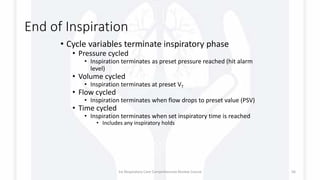
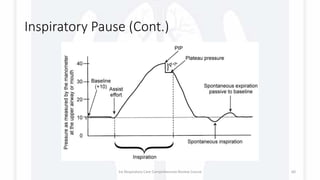
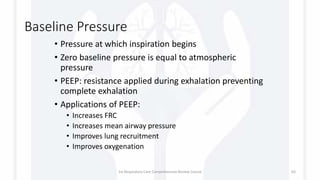
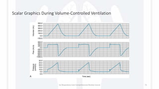
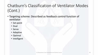
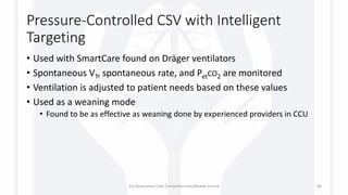
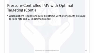
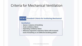
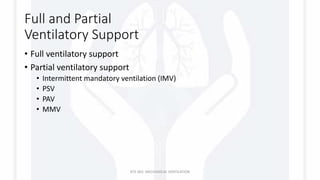
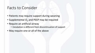
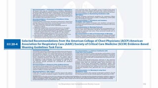
![Differential pressure flow
sensor
• As flow passes through the sensor’s resistive
element a pressure deference develop
• Using Boyle’s Law [P1V1 = P2V2] the gas flow
can be calculated
• This type of sensors can be affected by
condensate, secretion and calcification.
• An example of a ventilator using this type of
sensors is Hamilton G5 & S1
1st Respiratory Care Comprehensive Review Course 33](https://image.slidesharecdn.com/rccrcmechanicalventilation1-170829075318/85/Mechanical-Ventilation-101-33-320.jpg)


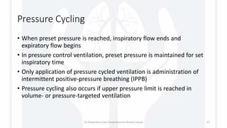

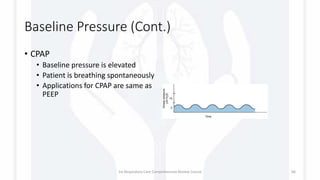

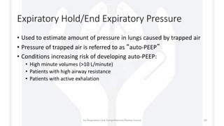


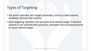


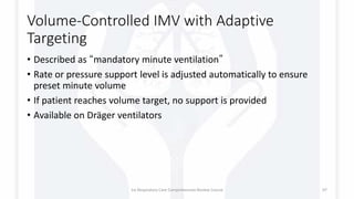

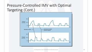


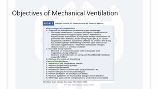


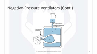
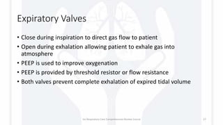
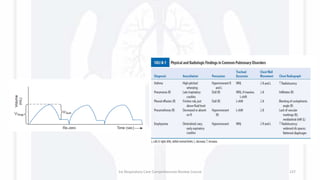
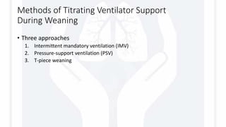
![ALARMS
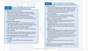
• Low-pressure alarms are usually set about 5 to 10 cm H2O below
PIP.
• High-pressure alarms are set about 10 cm H2O above PIP.
• Total Respiratory Rate alarm set about : high 10 Breaths above the
patient total rate; low as low as 6 to 8 BPM
• Low PEEP/continuous positive airway pressure (CPAP) alarms are
usually set about 2 to 5 cm H2O below the PEEP level.
• Apnea alarms are used to monitor mandatory or spontaneous
breaths. An apnea period of 20 seconds is the highest accepted
maximum. In some situations, apnea alarms are set so the patient
will not miss two consecutive machine breaths (apnea time > total
cycle time [TCT] and < [TCT × 2]).
• Low exhaled VT: 10% to 15% below set VT.
• Low exhaled minute volume: 10% to 15% below average minute
volume.
• FIO2: 5% above and below set oxygen percentage.
1st Respiratory Care Comprehensive Review Course 133](https://image.slidesharecdn.com/rccrcmechanicalventilation1-170829075318/85/Mechanical-Ventilation-101-133-320.jpg)


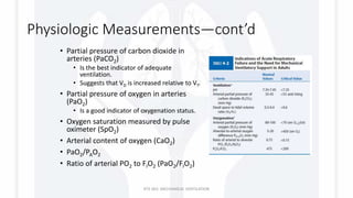
The document serves as a comprehensive review course on mechanical ventilation, detailing the physical characteristics and components of ventilators, including power sources, control systems, and breath delivery mechanisms. It outlines various types of ventilators, their operating principles, and the distinct phases involved in breath delivery, such as initiation, inspiration, and expiration. Additionally, the text discusses control variables for ventilation and emphasizes the role of feedback systems in maintaining desired ventilation parameters.


