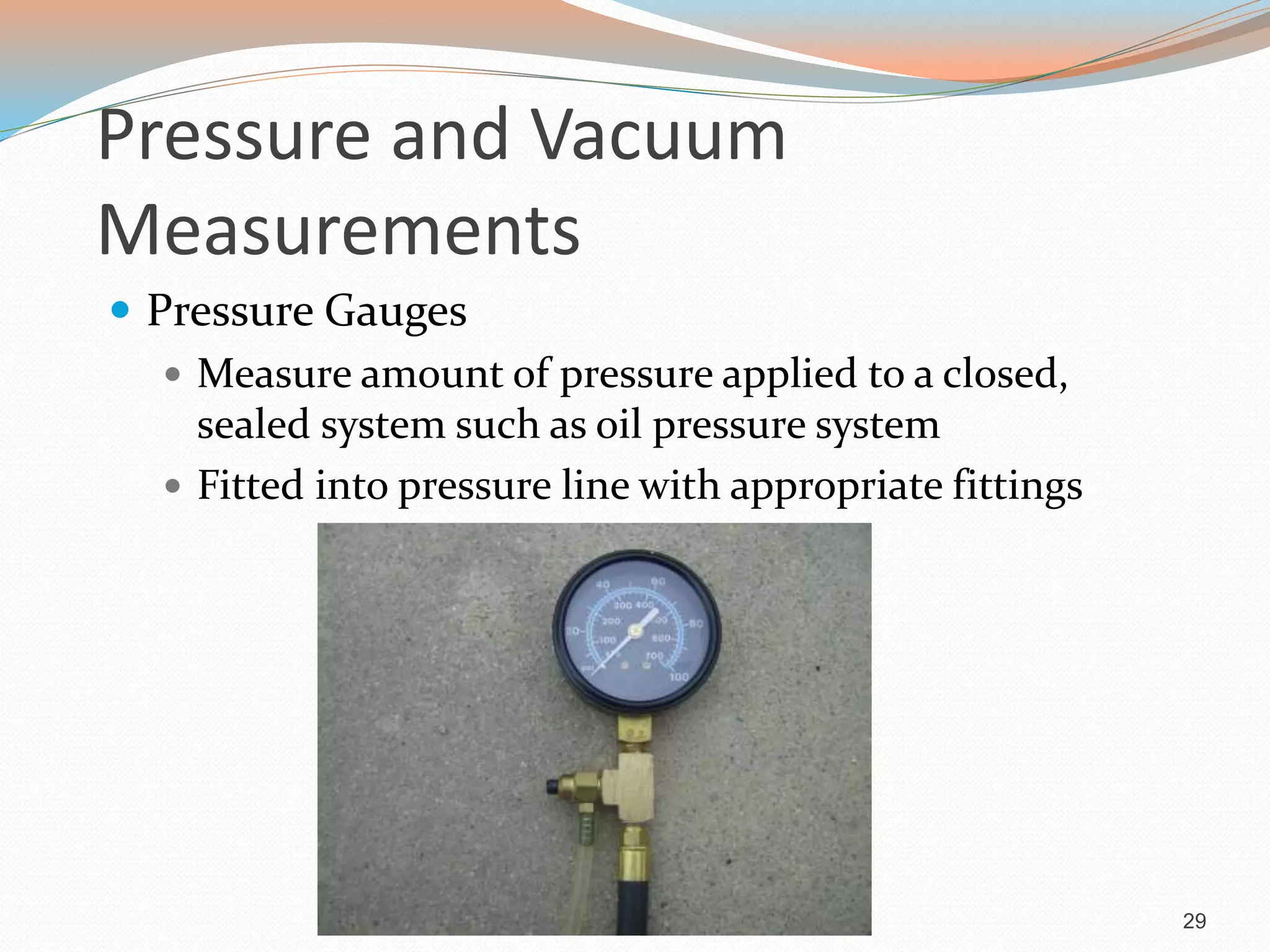
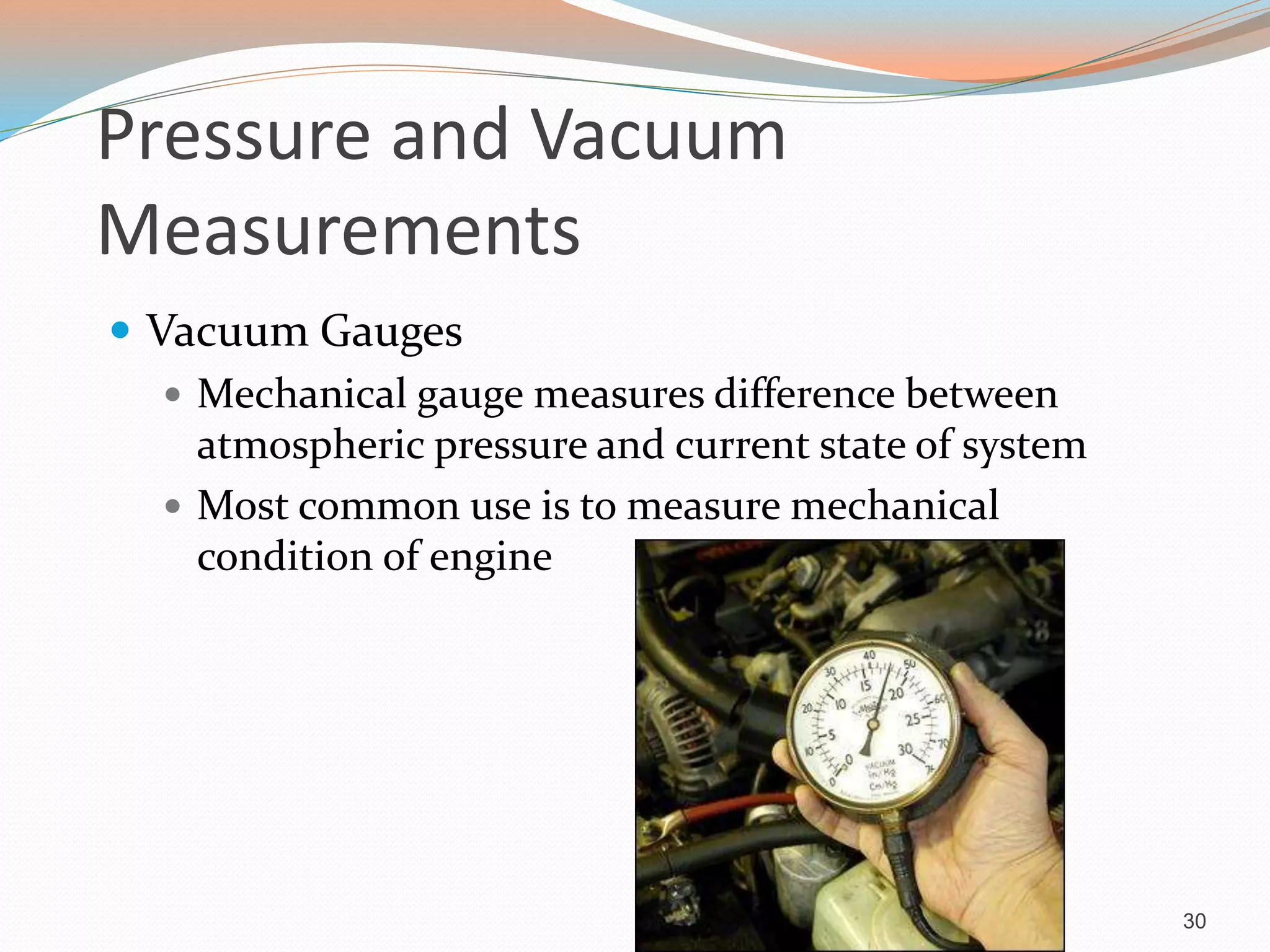
Measurements and Precision
Measuring Devices
Introduction
 Methods of collecting data depend on what is being
measured
 Check for excessive wear or damage when servicing
components
 Some shops send components out for these
measurements and tests
4
Measuring Systems
 Most common measurement in the U.S. is the United
States Customary (USC)
 Based on the inch ( 1” )
 Can be measured in decimals (1.000”) or fractions (1/16”)
 Engine measurements are expressed in thousandths of an
inch (0.001”)
5
Measuring Systems
 Metric system based on the meter
 Most common units in the automotive industry are the
centimeter (1cm) and millimeter (1mm)
 Millimeters are used to express close tolerances of
engine measurements
 Metric system is based on divisions of ten
 10mm=1cm
 10cm=1dm
 10dm=1 meter
6
Measurement Conversion
 Sometimes needed-measurement specifications are
not stated in the necessary format
 Ensure correct conversion factor is being used at all
times
 Sometimes conversion charts are readily available
 Key Notes page 44 has conversion chart
 To convert inches to mm, multiply inches by 25.4
 To convert mm to inches, divide mm by 25.4
7
Rulers and Feeler Gauges
 Rulers
 Simple tools to measure straight-line distances
where tolerances are not a major factor
 May be USC or metric
 Can be made of metal, plastic, or wood
 Typical rulers are 6 inches or 12 inches
 Drafting rulers can have several different scales
8
Typical Machinist Ruler
9
Rulers and Feeler Gauges
 Feeler Gauges
 Precision-machined piece of metal that is flat or
round
 May be USC or metric
 Used for measuring “gaps” or the space between two
objects
 Proper usage requires practice
11
12
Micrometers and Associated
Gauges
 Micrometers precisely measure different shapes of
a component
 Outside micrometers
 Resembles a clamp to measure linear distances
 Proper use requires practice and studying the
markings of the instrument
13
14
Micrometers and Associated
Gauges
 Micrometer Limitations
 In order to measure accurately, the micrometer must
be accurate itself
 User experience and “feel” can affect accuracy
 Extreme temperatures can also affect accuracy
15
Micrometers and Associated
Gauges
 Micrometer Calibration
 Performed using a standard gauge and an adjusting
tool
 Use proper length gauge for micrometer being
calibrated
16
Micrometers and Associated
Gauges
 Reading a USC Outside Micrometer
 Place anvil against work
 Rotate thimble to bring spindle into contact with
opposite side of work
 Use ratchet knob to ensure sufficient contact is made
 Remove micrometer and read dial
17
Micrometers and Associated
Gauges
 Reading a Metric Outside Micrometer
 Similar to USC micrometer except for size of scales
 Measurements vary from USC
 Follow steps in text
18
Micrometers and Associated
Gauges
 Telescopic Gauges
 Used with outside micrometers to measure inside
diameters
 Various lengths and T-shaped
 Extensions are spring-loaded
 Accuracy subject to user experience
20
Micrometers and Associated
Gauges
 Telescopic Gauges
 Leg has a rotatable handle to lock extensions in place
 Once gauge is removed, measure with outside
micrometer
21
Micrometers and Associated
Gauges
22
Telescopic Gauges
23
Micrometers and Associated
Gauges
 Inside Micrometers
 To measure inside of large holes
 May be USC or metric
 Spindles of different lengths can be installed to
match hole size
 Requires skill and practice for accurate
measurements
24
Small Hole Gauges
 To measure small holes
 Gauge is straight with a screw handle on one end and a
split ball on other
 Handle is turned to expand ball
 Removed and measured with a micrometer
25
Dial Indicators and Calipers
 Dial Indicators
 Easy way to check how far components can move
 Scale can be USC or metric
 Face can be balanced or continuous
 Used to check run-out or end-play
26
Dial Indicators and Calipers
 Dial Calipers
 For inside, outside, and depth measurements
 Manual scales or digital
 USC can measure in 0.001 inch increments
 Metric can measure in 0.02 millimeter increments
27
Pressure and Vacuum
Measurements
 Pressure Gauges
 Measure amount of pressure applied to a closed,
sealed system such as oil pressure system
 Fitted into pressure line with appropriate fittings
29
Pressure and Vacuum
Measurements
 Vacuum Gauges
 Mechanical gauge measures difference between
atmospheric pressure and current state of system
 Most common use is to measure mechanical
condition of engine
30
Summary
 Most common measurement system in United States
is the United States Customary or the English system
 Base USC measurement is the inch
 Base metric measurement is the meter
 Use proper measuring tool for the job
31

Measurements and precision measuring devices

  • 1.
  • 2.
    Introduction  Methods ofcollecting data depend on what is being measured  Check for excessive wear or damage when servicing components  Some shops send components out for these measurements and tests 4
  • 3.
    Measuring Systems  Mostcommon measurement in the U.S. is the United States Customary (USC)  Based on the inch ( 1” )  Can be measured in decimals (1.000”) or fractions (1/16”)  Engine measurements are expressed in thousandths of an inch (0.001”) 5
  • 4.
    Measuring Systems  Metricsystem based on the meter  Most common units in the automotive industry are the centimeter (1cm) and millimeter (1mm)  Millimeters are used to express close tolerances of engine measurements  Metric system is based on divisions of ten  10mm=1cm  10cm=1dm  10dm=1 meter 6
  • 5.
    Measurement Conversion  Sometimesneeded-measurement specifications are not stated in the necessary format  Ensure correct conversion factor is being used at all times  Sometimes conversion charts are readily available  Key Notes page 44 has conversion chart  To convert inches to mm, multiply inches by 25.4  To convert mm to inches, divide mm by 25.4 7
  • 6.
    Rulers and FeelerGauges  Rulers  Simple tools to measure straight-line distances where tolerances are not a major factor  May be USC or metric  Can be made of metal, plastic, or wood  Typical rulers are 6 inches or 12 inches  Drafting rulers can have several different scales 8
  • 7.
  • 8.
    Rulers and FeelerGauges  Feeler Gauges  Precision-machined piece of metal that is flat or round  May be USC or metric  Used for measuring “gaps” or the space between two objects  Proper usage requires practice 11
  • 9.
  • 10.
    Micrometers and Associated Gauges Micrometers precisely measure different shapes of a component  Outside micrometers  Resembles a clamp to measure linear distances  Proper use requires practice and studying the markings of the instrument 13
  • 11.
  • 12.
    Micrometers and Associated Gauges Micrometer Limitations  In order to measure accurately, the micrometer must be accurate itself  User experience and “feel” can affect accuracy  Extreme temperatures can also affect accuracy 15
  • 13.
    Micrometers and Associated Gauges Micrometer Calibration  Performed using a standard gauge and an adjusting tool  Use proper length gauge for micrometer being calibrated 16
  • 14.
    Micrometers and Associated Gauges Reading a USC Outside Micrometer  Place anvil against work  Rotate thimble to bring spindle into contact with opposite side of work  Use ratchet knob to ensure sufficient contact is made  Remove micrometer and read dial 17
  • 15.
    Micrometers and Associated Gauges Reading a Metric Outside Micrometer  Similar to USC micrometer except for size of scales  Measurements vary from USC  Follow steps in text 18
  • 16.
    Micrometers and Associated Gauges Telescopic Gauges  Used with outside micrometers to measure inside diameters  Various lengths and T-shaped  Extensions are spring-loaded  Accuracy subject to user experience 20
  • 17.
    Micrometers and Associated Gauges Telescopic Gauges  Leg has a rotatable handle to lock extensions in place  Once gauge is removed, measure with outside micrometer 21
  • 18.
  • 19.
  • 20.
    Micrometers and Associated Gauges Inside Micrometers  To measure inside of large holes  May be USC or metric  Spindles of different lengths can be installed to match hole size  Requires skill and practice for accurate measurements 24
  • 21.
    Small Hole Gauges To measure small holes  Gauge is straight with a screw handle on one end and a split ball on other  Handle is turned to expand ball  Removed and measured with a micrometer 25
  • 22.
    Dial Indicators andCalipers  Dial Indicators  Easy way to check how far components can move  Scale can be USC or metric  Face can be balanced or continuous  Used to check run-out or end-play 26
  • 23.
    Dial Indicators andCalipers  Dial Calipers  For inside, outside, and depth measurements  Manual scales or digital  USC can measure in 0.001 inch increments  Metric can measure in 0.02 millimeter increments 27
  • 24.
    Pressure and Vacuum Measurements Pressure Gauges  Measure amount of pressure applied to a closed, sealed system such as oil pressure system  Fitted into pressure line with appropriate fittings 29
  • 25.
    Pressure and Vacuum Measurements Vacuum Gauges  Mechanical gauge measures difference between atmospheric pressure and current state of system  Most common use is to measure mechanical condition of engine 30
  • 26.
    Summary  Most commonmeasurement system in United States is the United States Customary or the English system  Base USC measurement is the inch  Base metric measurement is the meter  Use proper measuring tool for the job 31