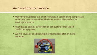
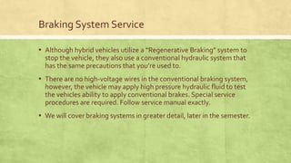
Hybrid Safety
And Service Procedures
HighVoltage Electrical Safety
▪ There have been electrical systems on vehicles for over 100 years. Up
until now there was a certain leniency for error.
▪ Hybrid vehicles often have high-voltage electrical systems.The
ability to identify a high voltage circuit, use the proper personal
protection equipment (PPE), and understand the electrical
characteristics of high-voltage systems will reduce the possibility of
serious injury or electrocution (death)
SafetyWarning!!!
ALWAYS FOLLOW MANUFACTURE DIAGNOSTIC AND REPAIR GUIDELINES AS
OUTLINED INTHE SERVICE MANUAL. FAILURETO DO SO WILL RESULT IN SERIOUS
INURY OR DEATH. EVEN IFYOUTHINKYOU KNOW WHATYOUR DOING , ORYOU’VE
DONE IT BEFORE….CHECK ANY WAY…..THINGS CHANGE AND ARE UPDATED ONLINE
QUICKLY!
FOLLOW EVERY STEP EXACTLY AS OUTLINED!!!!!!!!!!!!!!!!!!!!!!!!!!!!!!!!!!!!!!!!!!!!!!!!
Voltage Levels
Voltage Level DC AC Color
Low LessThan 30V LessThan 15V Red or Black
Intermediate Between 30V and 60V Between 15V and 30V Blue or Green
High MoreThan 60V MoreThan 30V ORANGE!
Electrical Shock occurs when current is conducted through the human
body.The amount of current and duration of electrical exposure through
a body determine the severity of shock and injuries. Current causes
injury,Voltage only provides the electrical pressure that forcesCurrent
through.
Current Levels
Current (mA) (milliamps) Effect
.5 to 1.5 Perceptible shock
1 to 5 Muscle Contraction
3 to 10 Pain
10 to 40 No-Let-GoThreshold
30 to 70 Respiratory Paralysis
75 to 100 Ventricular Fibrillation
250 to 300 Heart Paralysis
5000 to 6000 (5 to 6 amps) Organs Burn
• Ventricular Fibrillation is a condition in which heart convulsions stop the flow of
blood through the body.
• Electrical Pathway is also important (hand to hand, hand to foot, etc…)This is why
we follow the one hand rule when working on high voltage systems.
Current flow in the human body
Body Resistance Current (mA @ 120 volts) Description
3000 ohms 42 mA Larger Person
1750 ohms 72 mA Average Person
1230 ohms 102 mA Petite Person
• When the human body acts as a “load” it has resistance.The larger
the person the more resistance they carry.
• Follow “OHMS” Law to determine actual current at different
voltages.
• Keep working conditions DRY, including sweat (ohms law)
• Hybrid vehicles achieve voltage levels up to 650Volts!That’s over
five times as high as the above examples.
Equipment Safety Ratings
▪ There are several categories or “ratings” for over-voltage protection.
CAT I, CAT II, CAT III, and CAT IV.The higher the category, the greater
the protection to the technician when measuring high-energy
voltage.
▪ Marked on meters, leads, gloves, and other test equipment. (may be
sticker, molded, or stamp.)
▪ Hybrid electric vehicles are equipped with electrical systems whose
voltages can exceed 600 volts DC. A CAT III-certified digital multi-
meter is REQUIRED for making measurements on these systems.
CAT I
▪ Typically a CAT I meter is used for low-voltage measurements, such
as voltage measurements at wall outlets in the home. CAT I rated
meters are usually rated between 300 and 800 volts. CAT I is for low
energy levels. (Even though the voltage is high enough to work on a
hybrid vehicle, the energy protection is inadequate).
CAT II
▪ A higher-rated meter that would be typically used for checking
voltages at the circuit-breaker panel in the home. Meters with a CAT
II rating are usually rated between 300 and 600 volts. CAT II rated
meters have similar voltage ratings as a CAT I meter but the energy
level protection is higher (Think current, and arc-over scenarios)
CAT III
▪ This is the MINIMUM-rated meter that should be used for hybrid
vehicles. Meters with a CAT III rating are usually rated between 600
and 1000 volts and the highest energy level which is needed to
protect the technician when measuring circuits. (Although not
perfect).
CAT IV
▪ These meters are for clamp-on style only.They are used to measure
current in a circuit by sensing induction. If the meter has leads for
voltage, they are only rated to CAT III.
Safety Ratings
Be Careful Using Meters and Oscilloscopes!
• Using meters and scopes can create an
unintentional voltage difference (short)
through your body. (another reason to use the
one hand method, and differential probes.
• The small distance between floating circuit
and low voltage case ground can arc, causing
you to be part of the high voltage circuit. (Do
not test high voltage circuits compared to
chassis ground!)
Floating Ground
▪ High voltage systems utilize what is called a “Floating Ground”,
which means the Positive voltage returns to the battery through a
dedicated conductor (cable) instead of a common ground such as the
chassis.
▪ This gives an increase in safety, but is not perfect. Certain conditions,
such as insulation faults, and improper testing techniques can result
in serious injury or death.
Electrical Shock Potential
▪ Besides creating an arc-over between high and low voltage systems
with test tools, there are other places to be aware of dangers.
-Battery module contains HighVoltage, even if the correct de-power
procedure was followed.
-High voltage remains in the system after de-power for up to 15 min
(depends on manufacture)
-System main relays (SMR) can “weld” shut, preventing a complete de-
power.
Electrical Shock Potential
▪ Moisture in the air, and or on you (perspiration) can create a low
resistance path, inviting current discharge.
▪ Pushing an electric vehicle will create AC voltage at the three phase
leads from the traction motors….(this includes towing)
Differential Probe
▪ Use Differential Probes to isolate the Scope chassis
▪ Always use CAT III 1000v rated test equipment
▪ Measure circuits with “intent” and do not be “sloppy” with lead
placement.
InsulationTester
▪ A common tool used by technicians in testing and analyzing high-
voltage systems is an insulation tester.
▪ It is used to detect a reduction in resistance between high-voltage
circuits, components, or systems and the vehicle chassis.
InsulationTester
▪ Injects several different amounts of voltage/current into the into the
device under test. (110v, 250v, 500v, 1000v)
▪ It then measures the amount of voltage drop to determine the
resistance of the device or circuit.
▪ Care must be taken when using this tool, because it can provide an
electrical shock. (by the tool or arc-over from the high voltage
system)
Isolation Fault Monitoring
▪ The isolation fault detection system is an important element of safe
high-voltage circuit operation.The system monitors chassis ground
to determine if high voltage is leaking to the chassis.
▪ High voltage leakage to the chassis is a potentially fatal situation for
anyone who contacts high voltage components and the chassis at the
same time, and or is using test equipment.
Isolation Fault Monitoring
▪ Using a set of resistors, amplifiers, voltage regulators, and a digital
logic device the vehicle can determine if and roughly where the
isolation fault exists.
▪ The vehicle will set a code and disable the high-voltage system.
▪ We use this code and an insulation tester to determine where the
exact fault is.
Safety Interlock System
▪ A system used to detect when any high-voltage component or circuit
has been breached (disconnected or damaged).The controllers can
signal for the bus capacitors to be discharged and System Main
Relays (SMR) are turned off, to ensure that an individual will be safe
when working on a high-voltage circuit. (not guarantee, don’t count
your life on it)
RubberGloves
▪ Used to protect the user from electrocution, high voltage gloves are
to be used when working on live high voltage systems, or when the
condition of the system is unknown.
▪ There are two types of high voltage gloves,Type I andType II.
▪ Type I gloves are not ozone resistant
▪ Type II gloves are ozone resistant
RubberGloves
▪ Ozone is a form of oxygen that is found in the air surrounding a
conductor in high voltages. It can causes dangerous cracks to form in
rubber products, including insulating gloves
▪ There are six classifications high voltage gloves are rated at.
RubberGloves
RubberGloves
▪ Gloves MUST be inspected every six months by a qualified glove
inspection laboratory. (date of last inspection is on gloves)
▪ Gloves MUST be inspected by the user EVERY time they are used.
Visually inspect gloves for the following;
-Embedded foreign objects
-Holes, punctures, tears or cuts
-Ozone damage (fine cracks)
-Swelling, Softening, Sticky, or Hardening
-Damage from Chemicals/Burns
RubberGloves
▪ After Gloves have been visually inspected and checked for last
certification date, test gloves for air leaks by using a glove inflator
tool, or rolling the edges tight, and check for leaks. Also roll fingers
and edges while inspecting for fine cracks.
▪ DO NOT use the gloves if ANY of the tests fail.
▪ Lets test mine!!!
Eye Protection/Face Protection
▪ Eye protection/Face protection should be worn, anytime you are
working on a vehicle, including the high voltage system.
▪ Due to electrical blast/arc-over/explosion full face shield should be
worn.
▪ Needs to meet ANSI Z87.1 standards
▪ May include auto dimming for flash protection
Safety Cones and Fiberglass Pole
▪ Ford requires (and is a good idea) to have safety cones placed at the
four corners of the work area.
▪ Signs that state “HighVoltage-Do notTouch” should also be present.
▪ Ford also requires that a ten-foot insulated safety pole/hook be
present just outside of the safety zone.This pole is used to pull away
a technician in the case of an electrical accident. (notify coworkers
that you will be working on a high voltage system)
Hoisting A HybridVehicle
▪ When lifting a hybrid vehicle, take special care not to damage, the
high-voltage cables under the vehicle.
▪ Use designated lift points (found in service manual)
▪ High-voltage cables are not repairable and require replacement.
More SafetyTools
▪ Insulated tools offer an additional margin of safety when servicing
high-voltage systems.
▪ Lock box is the ONLY place to put vehicle keys, and de-power
disconnect switches/fuse when working on a hybrid or electric
vehicle.
Oil Change
▪ Silence is not “Golden”. Just because you don’t hear the ICE running
doesn’t mean it won’t just start up. Always look for the “Ready”
indicator when service the vehicle.
▪ The vehicle computer determines the mode which the vehicle
operates when in “Ready” mode, and can start the ICE at any time.
(including when the oil is drained, and your walking to parts dept.)
▪ Make sure vehicle is OFF and put keys in lock box at least 15 feet
away from vehicle.
Hybrid Power Modes
▪ OFF- All systems are off. Both the engine and electric drive systems
are disabled.
▪ ACCESSORY- Same as the ACCESSORY position in a conventional
vehicle. Power is available to select secondary systems but not to the
engine or electric drive.
▪ POWER ON- Equivalent to conventional “Key On, Engine Off”.The
ICE will not start on its own and the electric drive system will not
function. Data from the DLC is available from scan tool, and all other
systems are powered.
Hybrid Power Mode
▪ READY- Equivalent to “KEY ON, ENGINE RUNNING” (even though
the ICE is not running at this time). In this mode the vehicle is ready
to drive (propulsion in drive).The ICE is running or ready to run if so
commanded.This mode usually requires foot on the brake while
pressing the “Push to Start” button.
NOTE: Remember to keep system OFF with the key at least 15 feet away in a lock box
(only you have the key to the lock box) whenever servicing the vehicle.
Capacitor Discharge
▪ Capacitors are used in the inverter, and can hold high-voltage for a
very long time, creating a potentially deadly situation. Manufactures
engineered a system to help discharge this condition.
▪ PASSIVE DISCHARGE- A circuit that uses resistors to slowly
discharge the high-voltage system in about 5-10 minutes (roughly).
▪ ACTIVE DISCHARGE- A circuit that uses electronic components to
quickly discharge the high-voltage system into the stator in less than
5 seconds (roughly).
NOTE: NEVER assume these circuits are working as designed or the system is discharged,
ALWAYS check for your self using safe methods, and appropriate tools before servicing.
Electronic Power Steering (EPS) or (EPAS)
▪ Most Hybrid and a lot of newer vehicles use electronic power
steering.These can be powered with one of two voltages.
▪ 12Volts-These systems can be identified by the red or black wires
and often use an inverter that increases the voltage to 42 volts. (the
high voltage is self contained in the actuator and shouldn’t present a
danger, but follow manufactures service procedures)
▪ 42Volts-These systems are identified by a yellow or blue conduit
cover.This voltage level is not a shock hazard but can maintain an arc
if a circuit is opened or shorted (fire/heat damage).
NOTE: ALWAYS follow manufacture service procedures when working on electronic power
steering systems to prevent injury or damage.
Electronic Power Steering (EPS) or (EPAS)
▪ If the above operations are not performed properly, the steering
center point (zero point) will deviate, which may lead to a difference
in steering effort between turning right and left. If there is a
difference in steering effort (left/right), perform the torque sensor
zero point calibration whenever this problem happens or new parts
are installed.
NOTE:When disconnecting the connectors relating to the electronic
power steering system, first center the steering wheel, then turn the
ignition switch ON, then turn the ignition switch OFF, then disconnect
the connectors. Do not turn the ignition switch ON when the steering
wheel is not centered.
Electronic Power Steering (EPS) or (EPAS)
12Volt Auxiliary Battery
▪ When servicing the conventional 12 volt battery all normal service
precautions apply.The 12 volt system (which makes up 90% of the
electrical circuits) is isolated from the high-voltage system.
▪ The 12 volt batteries are usually smaller and designed differently,
using a “Absorbed Glass Matt” (AGM) design.These batteries require
a special charger. (like Optima)
Cooling Systems
▪ Some hybrids utilize a hot storage tank, that can hold water
temperatures at operating temperature for up to three days.
EXTREME caution should be observed when working on the cooling
system. Follow all service procedures EXACTLY to minimize injury.
▪ We will cover cooling systems in more detail later in the semester.
Air Conditioning Service
▪ Many hybrid vehicles use a high-voltage air-conditioning compressor,
and safety precautions should be used. Follow all manufacture
service procedures.
▪ Hybrids also utilize a different non-conductive oil for the air-
conditioning system.
▪ We will cover air-conditioning in greater detail later on in the
semester.
Braking System Service
▪ Although hybrid vehicles utilize a “Regenerative Braking” system to
stop the vehicle, they also use a conventional hydraulic system that
has the same precautions that you’re used to.
▪ There are no high-voltage wires in the conventional braking system,
however, the vehicle may apply high pressure hydraulic fluid to test
the vehicles ability to apply conventional brakes. Special service
procedures are required. Follow service manual exactly.
▪ We will cover braking systems in greater detail, later in the semester.
Brake System Service
Questions?

Hybrid safety

  • 1.
  • 2.
    HighVoltage Electrical Safety ▪There have been electrical systems on vehicles for over 100 years. Up until now there was a certain leniency for error. ▪ Hybrid vehicles often have high-voltage electrical systems.The ability to identify a high voltage circuit, use the proper personal protection equipment (PPE), and understand the electrical characteristics of high-voltage systems will reduce the possibility of serious injury or electrocution (death)
  • 3.
    SafetyWarning!!! ALWAYS FOLLOW MANUFACTUREDIAGNOSTIC AND REPAIR GUIDELINES AS OUTLINED INTHE SERVICE MANUAL. FAILURETO DO SO WILL RESULT IN SERIOUS INURY OR DEATH. EVEN IFYOUTHINKYOU KNOW WHATYOUR DOING , ORYOU’VE DONE IT BEFORE….CHECK ANY WAY…..THINGS CHANGE AND ARE UPDATED ONLINE QUICKLY! FOLLOW EVERY STEP EXACTLY AS OUTLINED!!!!!!!!!!!!!!!!!!!!!!!!!!!!!!!!!!!!!!!!!!!!!!!!
  • 4.
    Voltage Levels Voltage LevelDC AC Color Low LessThan 30V LessThan 15V Red or Black Intermediate Between 30V and 60V Between 15V and 30V Blue or Green High MoreThan 60V MoreThan 30V ORANGE! Electrical Shock occurs when current is conducted through the human body.The amount of current and duration of electrical exposure through a body determine the severity of shock and injuries. Current causes injury,Voltage only provides the electrical pressure that forcesCurrent through.
  • 5.
    Current Levels Current (mA)(milliamps) Effect .5 to 1.5 Perceptible shock 1 to 5 Muscle Contraction 3 to 10 Pain 10 to 40 No-Let-GoThreshold 30 to 70 Respiratory Paralysis 75 to 100 Ventricular Fibrillation 250 to 300 Heart Paralysis 5000 to 6000 (5 to 6 amps) Organs Burn • Ventricular Fibrillation is a condition in which heart convulsions stop the flow of blood through the body. • Electrical Pathway is also important (hand to hand, hand to foot, etc…)This is why we follow the one hand rule when working on high voltage systems.
  • 6.
    Current flow inthe human body Body Resistance Current (mA @ 120 volts) Description 3000 ohms 42 mA Larger Person 1750 ohms 72 mA Average Person 1230 ohms 102 mA Petite Person • When the human body acts as a “load” it has resistance.The larger the person the more resistance they carry. • Follow “OHMS” Law to determine actual current at different voltages. • Keep working conditions DRY, including sweat (ohms law) • Hybrid vehicles achieve voltage levels up to 650Volts!That’s over five times as high as the above examples.
  • 7.
    Equipment Safety Ratings ▪There are several categories or “ratings” for over-voltage protection. CAT I, CAT II, CAT III, and CAT IV.The higher the category, the greater the protection to the technician when measuring high-energy voltage. ▪ Marked on meters, leads, gloves, and other test equipment. (may be sticker, molded, or stamp.) ▪ Hybrid electric vehicles are equipped with electrical systems whose voltages can exceed 600 volts DC. A CAT III-certified digital multi- meter is REQUIRED for making measurements on these systems.
  • 8.
    CAT I ▪ Typicallya CAT I meter is used for low-voltage measurements, such as voltage measurements at wall outlets in the home. CAT I rated meters are usually rated between 300 and 800 volts. CAT I is for low energy levels. (Even though the voltage is high enough to work on a hybrid vehicle, the energy protection is inadequate).
  • 9.
    CAT II ▪ Ahigher-rated meter that would be typically used for checking voltages at the circuit-breaker panel in the home. Meters with a CAT II rating are usually rated between 300 and 600 volts. CAT II rated meters have similar voltage ratings as a CAT I meter but the energy level protection is higher (Think current, and arc-over scenarios)
  • 10.
    CAT III ▪ Thisis the MINIMUM-rated meter that should be used for hybrid vehicles. Meters with a CAT III rating are usually rated between 600 and 1000 volts and the highest energy level which is needed to protect the technician when measuring circuits. (Although not perfect).
  • 11.
    CAT IV ▪ Thesemeters are for clamp-on style only.They are used to measure current in a circuit by sensing induction. If the meter has leads for voltage, they are only rated to CAT III.
  • 12.
  • 13.
    Be Careful UsingMeters and Oscilloscopes! • Using meters and scopes can create an unintentional voltage difference (short) through your body. (another reason to use the one hand method, and differential probes. • The small distance between floating circuit and low voltage case ground can arc, causing you to be part of the high voltage circuit. (Do not test high voltage circuits compared to chassis ground!)
  • 14.
    Floating Ground ▪ Highvoltage systems utilize what is called a “Floating Ground”, which means the Positive voltage returns to the battery through a dedicated conductor (cable) instead of a common ground such as the chassis. ▪ This gives an increase in safety, but is not perfect. Certain conditions, such as insulation faults, and improper testing techniques can result in serious injury or death.
  • 15.
    Electrical Shock Potential ▪Besides creating an arc-over between high and low voltage systems with test tools, there are other places to be aware of dangers. -Battery module contains HighVoltage, even if the correct de-power procedure was followed. -High voltage remains in the system after de-power for up to 15 min (depends on manufacture) -System main relays (SMR) can “weld” shut, preventing a complete de- power.
  • 16.
    Electrical Shock Potential ▪Moisture in the air, and or on you (perspiration) can create a low resistance path, inviting current discharge. ▪ Pushing an electric vehicle will create AC voltage at the three phase leads from the traction motors….(this includes towing)
  • 17.
    Differential Probe ▪ UseDifferential Probes to isolate the Scope chassis ▪ Always use CAT III 1000v rated test equipment ▪ Measure circuits with “intent” and do not be “sloppy” with lead placement.
  • 18.
    InsulationTester ▪ A commontool used by technicians in testing and analyzing high- voltage systems is an insulation tester. ▪ It is used to detect a reduction in resistance between high-voltage circuits, components, or systems and the vehicle chassis.
  • 19.
    InsulationTester ▪ Injects severaldifferent amounts of voltage/current into the into the device under test. (110v, 250v, 500v, 1000v) ▪ It then measures the amount of voltage drop to determine the resistance of the device or circuit. ▪ Care must be taken when using this tool, because it can provide an electrical shock. (by the tool or arc-over from the high voltage system)
  • 20.
    Isolation Fault Monitoring ▪The isolation fault detection system is an important element of safe high-voltage circuit operation.The system monitors chassis ground to determine if high voltage is leaking to the chassis. ▪ High voltage leakage to the chassis is a potentially fatal situation for anyone who contacts high voltage components and the chassis at the same time, and or is using test equipment.
  • 21.
    Isolation Fault Monitoring ▪Using a set of resistors, amplifiers, voltage regulators, and a digital logic device the vehicle can determine if and roughly where the isolation fault exists. ▪ The vehicle will set a code and disable the high-voltage system. ▪ We use this code and an insulation tester to determine where the exact fault is.
  • 22.
    Safety Interlock System ▪A system used to detect when any high-voltage component or circuit has been breached (disconnected or damaged).The controllers can signal for the bus capacitors to be discharged and System Main Relays (SMR) are turned off, to ensure that an individual will be safe when working on a high-voltage circuit. (not guarantee, don’t count your life on it)
  • 23.
    RubberGloves ▪ Used toprotect the user from electrocution, high voltage gloves are to be used when working on live high voltage systems, or when the condition of the system is unknown. ▪ There are two types of high voltage gloves,Type I andType II. ▪ Type I gloves are not ozone resistant ▪ Type II gloves are ozone resistant
  • 24.
    RubberGloves ▪ Ozone isa form of oxygen that is found in the air surrounding a conductor in high voltages. It can causes dangerous cracks to form in rubber products, including insulating gloves ▪ There are six classifications high voltage gloves are rated at.
  • 25.
  • 26.
    RubberGloves ▪ Gloves MUSTbe inspected every six months by a qualified glove inspection laboratory. (date of last inspection is on gloves) ▪ Gloves MUST be inspected by the user EVERY time they are used. Visually inspect gloves for the following; -Embedded foreign objects -Holes, punctures, tears or cuts -Ozone damage (fine cracks) -Swelling, Softening, Sticky, or Hardening -Damage from Chemicals/Burns
  • 27.
    RubberGloves ▪ After Gloveshave been visually inspected and checked for last certification date, test gloves for air leaks by using a glove inflator tool, or rolling the edges tight, and check for leaks. Also roll fingers and edges while inspecting for fine cracks. ▪ DO NOT use the gloves if ANY of the tests fail. ▪ Lets test mine!!!
  • 28.
    Eye Protection/Face Protection ▪Eye protection/Face protection should be worn, anytime you are working on a vehicle, including the high voltage system. ▪ Due to electrical blast/arc-over/explosion full face shield should be worn. ▪ Needs to meet ANSI Z87.1 standards ▪ May include auto dimming for flash protection
  • 29.
    Safety Cones andFiberglass Pole ▪ Ford requires (and is a good idea) to have safety cones placed at the four corners of the work area. ▪ Signs that state “HighVoltage-Do notTouch” should also be present. ▪ Ford also requires that a ten-foot insulated safety pole/hook be present just outside of the safety zone.This pole is used to pull away a technician in the case of an electrical accident. (notify coworkers that you will be working on a high voltage system)
  • 30.
    Hoisting A HybridVehicle ▪When lifting a hybrid vehicle, take special care not to damage, the high-voltage cables under the vehicle. ▪ Use designated lift points (found in service manual) ▪ High-voltage cables are not repairable and require replacement.
  • 31.
    More SafetyTools ▪ Insulatedtools offer an additional margin of safety when servicing high-voltage systems. ▪ Lock box is the ONLY place to put vehicle keys, and de-power disconnect switches/fuse when working on a hybrid or electric vehicle.
  • 32.
    Oil Change ▪ Silenceis not “Golden”. Just because you don’t hear the ICE running doesn’t mean it won’t just start up. Always look for the “Ready” indicator when service the vehicle. ▪ The vehicle computer determines the mode which the vehicle operates when in “Ready” mode, and can start the ICE at any time. (including when the oil is drained, and your walking to parts dept.) ▪ Make sure vehicle is OFF and put keys in lock box at least 15 feet away from vehicle.
  • 33.
    Hybrid Power Modes ▪OFF- All systems are off. Both the engine and electric drive systems are disabled. ▪ ACCESSORY- Same as the ACCESSORY position in a conventional vehicle. Power is available to select secondary systems but not to the engine or electric drive. ▪ POWER ON- Equivalent to conventional “Key On, Engine Off”.The ICE will not start on its own and the electric drive system will not function. Data from the DLC is available from scan tool, and all other systems are powered.
  • 34.
    Hybrid Power Mode ▪READY- Equivalent to “KEY ON, ENGINE RUNNING” (even though the ICE is not running at this time). In this mode the vehicle is ready to drive (propulsion in drive).The ICE is running or ready to run if so commanded.This mode usually requires foot on the brake while pressing the “Push to Start” button. NOTE: Remember to keep system OFF with the key at least 15 feet away in a lock box (only you have the key to the lock box) whenever servicing the vehicle.
  • 35.
    Capacitor Discharge ▪ Capacitorsare used in the inverter, and can hold high-voltage for a very long time, creating a potentially deadly situation. Manufactures engineered a system to help discharge this condition. ▪ PASSIVE DISCHARGE- A circuit that uses resistors to slowly discharge the high-voltage system in about 5-10 minutes (roughly). ▪ ACTIVE DISCHARGE- A circuit that uses electronic components to quickly discharge the high-voltage system into the stator in less than 5 seconds (roughly). NOTE: NEVER assume these circuits are working as designed or the system is discharged, ALWAYS check for your self using safe methods, and appropriate tools before servicing.
  • 36.
    Electronic Power Steering(EPS) or (EPAS) ▪ Most Hybrid and a lot of newer vehicles use electronic power steering.These can be powered with one of two voltages. ▪ 12Volts-These systems can be identified by the red or black wires and often use an inverter that increases the voltage to 42 volts. (the high voltage is self contained in the actuator and shouldn’t present a danger, but follow manufactures service procedures) ▪ 42Volts-These systems are identified by a yellow or blue conduit cover.This voltage level is not a shock hazard but can maintain an arc if a circuit is opened or shorted (fire/heat damage). NOTE: ALWAYS follow manufacture service procedures when working on electronic power steering systems to prevent injury or damage.
  • 37.
    Electronic Power Steering(EPS) or (EPAS) ▪ If the above operations are not performed properly, the steering center point (zero point) will deviate, which may lead to a difference in steering effort between turning right and left. If there is a difference in steering effort (left/right), perform the torque sensor zero point calibration whenever this problem happens or new parts are installed. NOTE:When disconnecting the connectors relating to the electronic power steering system, first center the steering wheel, then turn the ignition switch ON, then turn the ignition switch OFF, then disconnect the connectors. Do not turn the ignition switch ON when the steering wheel is not centered.
  • 38.
  • 39.
    12Volt Auxiliary Battery ▪When servicing the conventional 12 volt battery all normal service precautions apply.The 12 volt system (which makes up 90% of the electrical circuits) is isolated from the high-voltage system. ▪ The 12 volt batteries are usually smaller and designed differently, using a “Absorbed Glass Matt” (AGM) design.These batteries require a special charger. (like Optima)
  • 40.
    Cooling Systems ▪ Somehybrids utilize a hot storage tank, that can hold water temperatures at operating temperature for up to three days. EXTREME caution should be observed when working on the cooling system. Follow all service procedures EXACTLY to minimize injury. ▪ We will cover cooling systems in more detail later in the semester.
  • 41.
    Air Conditioning Service ▪Many hybrid vehicles use a high-voltage air-conditioning compressor, and safety precautions should be used. Follow all manufacture service procedures. ▪ Hybrids also utilize a different non-conductive oil for the air- conditioning system. ▪ We will cover air-conditioning in greater detail later on in the semester.
  • 42.
    Braking System Service ▪Although hybrid vehicles utilize a “Regenerative Braking” system to stop the vehicle, they also use a conventional hydraulic system that has the same precautions that you’re used to. ▪ There are no high-voltage wires in the conventional braking system, however, the vehicle may apply high pressure hydraulic fluid to test the vehicles ability to apply conventional brakes. Special service procedures are required. Follow service manual exactly. ▪ We will cover braking systems in greater detail, later in the semester.
  • 43.
  • 45.