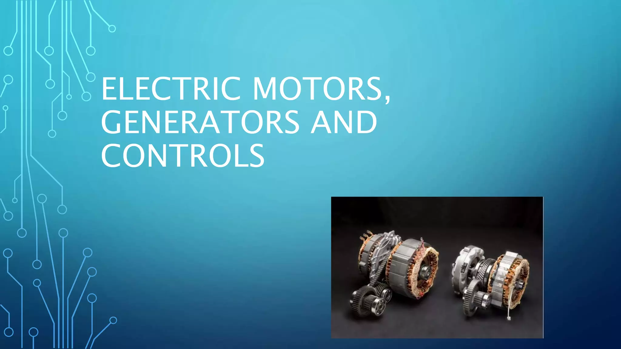
ELECTRIC MOTORS,
GENERATORS AND
CONTROLS
MAGNETISM
• Is a form of energy that is generated by the motion of electrons
and alignment of atoms.
• Can be naturally occurring in material called “Lodestone”
• Can be artificially created in some materials called “Ferrous”
(has iron)
MAGNETISM
TECH TIP: A cracked magnet becomes two weaker
magnets. This is an important concept to understand. A
cracked cam shaft or crank shaft position sensor may not
create a strong enough signal to be read by the computer .
LINES OF FORCE
• The lines that create a field of force around a magnet are
concentrated at both ends and form closed, parallel loops in
three dimensions that never intersect each other.
• The stronger the magnet the more lines of flux.
ATTRACTING OR REPELLING
• The poles of a magnet are called north and south because when
a magnet is suspended freely, the poles tend to point toward
the north and south poles of the earth.
• Magnetic force is equal at both ends.
• When unlike poles are placed closed together, the lines exit
from one magnet and enter the other, pulling or “attracting”
together.
• When like poles are placed closed together, the lines meet
head-on, forcing the magnets apart.
PERMEABILITY
• Magnetic flux CANNOT be insulated. There is no known
material through which magnetic force does not pass. However,
some materials allow the force to pass through more easily
than others.
• The degree of passage is called permeability.
• This is how Hall Effect sensors work
RELUCTANCE
• While there is no absolute insulation to magnetism, certain
materials resist the passages of magnetic forces.
• This can be compared to resistance within an electrical circuit.
• Air does not allow easy passage, so therefore it has a high
reluctance.
• Magnetism follows the path of least resistance.
ELECTROMAGNETISM
• Electricity and magnetism are related. One can be used to
create the other.
• Current flowing through a wire creates a magnetic field around
the wire.
• Moving a wire through a magnetic field creates current flow in
the wire. (or moving a magnetic field across a wire, known as
induction)
STRAIGHT CONDUCTOR
• The magnetic field surrounding a straight, current-carrying
conductor exists along the entire length of the wire.
• The strength determines how many flux lines and how far out
they are.
FIELD INTERACTION
• The lines of flux surrounding the conductors interact with other
magnetic fields.
• If two conductors carry current in opposite directions, their
magnetic fields also rotate in opposite directions.
• If they are placed side-by-side, the opposing flux lines create a
strong magnetic field.
• Current-carrying conductors move out of a strong field into a
weak field.
FIELD INTERACTION
MOTOR PRINCIPLE
• Electric motors, such as automotive starters, use this field
interaction to change electrical energy into mechanical energy.
• If two current carrying conductors are placed in a strong
magnetic field the conductor interacts with the magnetic field
poles, causing the conductor to move out of the strong field
and into the weaker (movement).
• This causes the neutral plane to shift (see picture)
MOTOR PRINCIPLE
MOTOR PRINCIPLE
ELECTROMAGNETIC INDUCTION
• Magnetic flux lines can create an electromotive force (voltage).
• Voltage is induced when magnetic flux lines are broken by a
conductor.
• Either the conductor or the magnetic field HAS to move for this
to occur.
• The highest voltage is induced when the motion is at right
angles.
ELECTROMAGENTIC STRENGTH
• Induced voltage depends on magnetic flux lines being broken
by a conductor. The strength of the voltage are increased four
ways:
1. Increase the strength of the magnetic field.
2. Increase the number of conductors that are breaking the flux
lines.
3. Increase the speed of the relative motion between the
conductor and flux.
4. Increase the angle between flux lines and conductor (90
ELECTRIC MOTOR POWER
• Electric motor power is expressed in kilowatts (kW).
• A watt is the amount of power needed to lift an object weight
102 grams a distance of one meter in one second.
• One “HP” is equal to 746 Watts. So a 15kW electric motor
produces 20 HP. (Honda IMA motor)
DC MOTOR PRINCIPLES
DC motors strength and speed are affected by the following:
1. Applied Voltage (speed)
2. Applied Current (torque)
One disadvantage to DC electric motors are the brushes arc and
wear out.
BRUSHLESS MOTORS
• There are two types of AC brushless motors:
1. AC Induction asynchronous motor
2. AC Permanent magnet synchronous motor
AC INDUCTION ASYNCHRONOUS MOTOR
• This style motor uses electromagnetic induction from the stator
to induce a current and therefore creates a magnetic field in the
rotor without the need of brushes or applied voltage to the
rotor.
• An AC induction asynchronous motor is called that because it
allows a certain amount of slip between the rotor and the
changing magnetic field in the stator.
AC PERMANENT MAGNET SYNCHRONOUS
MOTOR
• This motor uses a permanent magnetic rotor that interacts with
the changing magnetic field of the stator.
• Called synchronous because the speed of the rotor is the same
as the speed of the changing magnetic field in the stator.
ROTATING MAGNETIC FIELD
DC Motor operation
Asynchronous three phase AC induction motor operation
Synchronous three phase AC permanent magnet motor operation
GENERATORS?
• A generator is similar to a motor. However, a motor changes
electrical energy to mechanical energy, whereas a generator
changes mechanical energy to electrical energy.
• To generate voltage, a conductor is moved through a magnetic
field or a magnetic field is moved over a conductor (remember)
• The conductor or field is moved by mechanical energy.
AC GENERATOR
• In an AC generator, a spinning magnetic field (rotor) rotates
inside the stator (windings).
• As the spinning north and south poles of the rotor pass the
conductors (stator windings) they induce a voltage that flows in
one direction, then as the rotor rotates in the opposite
direction.
DC GENERATOR
• A DC generator provides direct current. The biggest difference
between a motor and generator is wiring to the armature
(rotor).
• In a motor the armature receives current from a power source.
• In a generator the rotor is driven by a mechanical device
creating an AC voltage in the armature, reacting with the stator
windings to induce voltage.
DC GENERATOR
• The voltage induced is AC unless you reverse the polarity of the
stator output at the same time the voltage in the armature is
reversed.
• This is accomplished by a commutator. The commutator has
segments that reverse output when the armature voltage is
reversed.
STATOR WIRING CONFIGURATION
• Stators can be wired in a “wye” or a “delta” configuration.
• Designers can use either configuration depending on the
application of the electric machine and the levels of power at a
rated rpm.
• Named based on schematic wiring, not visual representation.
DELTA CONFIGURATION
• The delta winding received its name because its shape
resembles the greek letter delta.
• Delta windings are used when higher amperages are needed.
(lower volts)
WYE CONFIGURATION
• The wye winding resembles the letter “Y”.
• Wye winding configurations are used in applications where high
volts at low speeds are required.
MOTOR CONTROL
• Most hybrids use an AC synchronous motor and is controlled as
follows:
1. To change the speed of the motor the frequency of the
applied current is changed. (Rotor and Stator move at same
speed, synchronized)
2. The pulse-width and voltage is adjusted to change the
current, which controls the power output. (torque)
MOTOR CONTROL MODULE
• All electric machines use a module to control electric motor
torque, speed, and direction.
• The module monitors various inputs and rotor position to
determine which driver circuits to the stator (electric motor) are
turned on.
• Module also monitors current with hall effect sensors in each of
the electric stator windings. (uses current and rotor
position/direction/speed to determine torque)
HALL EFFECT CURRENT SENSORS
RESOLVERS AND ENCODERS
• Mild hybrids don’t start off in electric mode, so they can utilize
an encoders. Encoders can’t determine exact rotor position.
• Since full hybrids can start off in electric mode, the module
needs to know the EXACT position of the rotor to synchronize
the electric motor and generate rotation. It achieves this
through the use of a “Resolver”. Sometimes the terms resolver
and encoder are interchanged.
RESOLVER
• A resolver is a sensor that provides two sine waves to a motor
controller to indicate absolute rotor position, direction, and
speed. It can detect position when stationary.
• The inverter sends an AC voltage signal to an exciter winding in
the sensor. This creates a magnetic field.
• The rotor end is elliptical, causing deviations in the magnetic
field as it passes the other two windings.
RESOLVER
CAPACITORS
• Capacitors consist of two conductive plates with an insulating
material between them (dielectric).
• When a capacitor is placed in a closed circuit to a battery.
Because electrons can’t flow through the capacitor, excess
electrons collect on what becomes the negatively charged plate.
• At the same time the other plate loses electrons, becoming
positively charged.
CAPACITORS
• Current continues until the voltage charge across the capacitor
equals source voltage.
• Capacitors are used to suppress voltage spikes, and
supplement voltage losses.
• Capacitors are also known as condensers because they
“condense” electrons.
NOTE: ALWAYS assume capacitors are
charged, until proven to be discharged.
Treat all circuits attached as potentially
deadly.
CAPACITORS
CAPACITORS
• Rated in microfarads (ability to store a charge) at a specific
voltage.
• Can’t determine how deadly based on microfarads, must also
consider voltage.
SNUBBERS
• Used to control the high-voltage surges that occur in circuits
containing coils that are switched on and off.
• Used to protect the switching device. (alternate path)
INVERTER
• Current flow through the electric motor stator is controlled by
six Insulated Gate Bipolar Transistors (IGBT’s) by the control
module.
• The inverter by definition inverts high-voltage DC current to
high-voltage three phase AC current. (120 degrees apart)
• Transistor base is controlled by fiber
optics to isolate the voltages.
INVERTER
• May not create a perfect sine wave. It may be various stages of
rectangular signals, depending on voltage level, efficiency, and
horse power demand.
INVERTER
CONVERTERS
• There can be several inverters and converters in a hybrid.
• By definition a converter, either converts high-voltage AC
current to high-voltage DC current, or converts high-voltage
DC current to low-voltage DC current (DC to DC converter)
CONVERTER
• Using fly-back diodes (one way check valves) connected to the
IGBT’s, the inverter can convert AC to DC.
• Works like an alternator diode rectifier bridge.
DC TO DC CONVERTER
• We are all used to DC to DC converters, but may not know it.
PCM’s use a DC to DC converter to convert 12-14V system to
5V system for its Voltage Reference circuit (sensors)
• Hybrids utilize this kind of converter to replace the alternator.
It converts the high-voltage DC current in the battery to 14
volts. It uses this voltage to act as an alternator, charging the
auxiliary system.
BOOST CONVERTER
• Can be used to increase voltage from the battery pack to the
electric motor.
• Works like the converter that lowers voltage but the primary
and secondary windings are changed to increase voltage.
OVER MODULATION
• The computer can control the IGBT’s in the inverter to alter the
sine wave of the three phase AC voltage to increase horsepower
and voltage. The trade off is it becomes less efficient.
• Think average voltage.
• Increases motor temperature.
COOLING THE INVERTER/CONVERTER
• Current flow and the electronic devices in a hybrid vehicle
produce a lot of heat. Toyota, Ford, and GM use liquid cooling
to control temperatures.
• Usually consists of a separate cooling system, or loop with its
own valve (not thermostat) and electric pump.
LETS CHECK IT OUT IN ACTION!
Compliments of Toyota!

Electric motors, generators and controls

  • 1.
  • 2.
    MAGNETISM • Is aform of energy that is generated by the motion of electrons and alignment of atoms. • Can be naturally occurring in material called “Lodestone” • Can be artificially created in some materials called “Ferrous” (has iron)
  • 3.
    MAGNETISM TECH TIP: Acracked magnet becomes two weaker magnets. This is an important concept to understand. A cracked cam shaft or crank shaft position sensor may not create a strong enough signal to be read by the computer .
  • 4.
    LINES OF FORCE •The lines that create a field of force around a magnet are concentrated at both ends and form closed, parallel loops in three dimensions that never intersect each other. • The stronger the magnet the more lines of flux.
  • 5.
    ATTRACTING OR REPELLING •The poles of a magnet are called north and south because when a magnet is suspended freely, the poles tend to point toward the north and south poles of the earth. • Magnetic force is equal at both ends. • When unlike poles are placed closed together, the lines exit from one magnet and enter the other, pulling or “attracting” together. • When like poles are placed closed together, the lines meet head-on, forcing the magnets apart.
  • 6.
    PERMEABILITY • Magnetic fluxCANNOT be insulated. There is no known material through which magnetic force does not pass. However, some materials allow the force to pass through more easily than others. • The degree of passage is called permeability. • This is how Hall Effect sensors work
  • 7.
    RELUCTANCE • While thereis no absolute insulation to magnetism, certain materials resist the passages of magnetic forces. • This can be compared to resistance within an electrical circuit. • Air does not allow easy passage, so therefore it has a high reluctance. • Magnetism follows the path of least resistance.
  • 8.
    ELECTROMAGNETISM • Electricity andmagnetism are related. One can be used to create the other. • Current flowing through a wire creates a magnetic field around the wire. • Moving a wire through a magnetic field creates current flow in the wire. (or moving a magnetic field across a wire, known as induction)
  • 9.
    STRAIGHT CONDUCTOR • Themagnetic field surrounding a straight, current-carrying conductor exists along the entire length of the wire. • The strength determines how many flux lines and how far out they are.
  • 10.
    FIELD INTERACTION • Thelines of flux surrounding the conductors interact with other magnetic fields. • If two conductors carry current in opposite directions, their magnetic fields also rotate in opposite directions. • If they are placed side-by-side, the opposing flux lines create a strong magnetic field. • Current-carrying conductors move out of a strong field into a weak field.
  • 11.
  • 12.
    MOTOR PRINCIPLE • Electricmotors, such as automotive starters, use this field interaction to change electrical energy into mechanical energy. • If two current carrying conductors are placed in a strong magnetic field the conductor interacts with the magnetic field poles, causing the conductor to move out of the strong field and into the weaker (movement). • This causes the neutral plane to shift (see picture)
  • 13.
  • 14.
  • 15.
    ELECTROMAGNETIC INDUCTION • Magneticflux lines can create an electromotive force (voltage). • Voltage is induced when magnetic flux lines are broken by a conductor. • Either the conductor or the magnetic field HAS to move for this to occur. • The highest voltage is induced when the motion is at right angles.
  • 16.
    ELECTROMAGENTIC STRENGTH • Inducedvoltage depends on magnetic flux lines being broken by a conductor. The strength of the voltage are increased four ways: 1. Increase the strength of the magnetic field. 2. Increase the number of conductors that are breaking the flux lines. 3. Increase the speed of the relative motion between the conductor and flux. 4. Increase the angle between flux lines and conductor (90
  • 17.
    ELECTRIC MOTOR POWER •Electric motor power is expressed in kilowatts (kW). • A watt is the amount of power needed to lift an object weight 102 grams a distance of one meter in one second. • One “HP” is equal to 746 Watts. So a 15kW electric motor produces 20 HP. (Honda IMA motor)
  • 18.
    DC MOTOR PRINCIPLES DCmotors strength and speed are affected by the following: 1. Applied Voltage (speed) 2. Applied Current (torque) One disadvantage to DC electric motors are the brushes arc and wear out.
  • 19.
    BRUSHLESS MOTORS • Thereare two types of AC brushless motors: 1. AC Induction asynchronous motor 2. AC Permanent magnet synchronous motor
  • 20.
    AC INDUCTION ASYNCHRONOUSMOTOR • This style motor uses electromagnetic induction from the stator to induce a current and therefore creates a magnetic field in the rotor without the need of brushes or applied voltage to the rotor. • An AC induction asynchronous motor is called that because it allows a certain amount of slip between the rotor and the changing magnetic field in the stator.
  • 21.
    AC PERMANENT MAGNETSYNCHRONOUS MOTOR • This motor uses a permanent magnetic rotor that interacts with the changing magnetic field of the stator. • Called synchronous because the speed of the rotor is the same as the speed of the changing magnetic field in the stator.
  • 22.
  • 23.
  • 24.
    Asynchronous three phaseAC induction motor operation
  • 25.
    Synchronous three phaseAC permanent magnet motor operation
  • 26.
    GENERATORS? • A generatoris similar to a motor. However, a motor changes electrical energy to mechanical energy, whereas a generator changes mechanical energy to electrical energy. • To generate voltage, a conductor is moved through a magnetic field or a magnetic field is moved over a conductor (remember) • The conductor or field is moved by mechanical energy.
  • 27.
    AC GENERATOR • Inan AC generator, a spinning magnetic field (rotor) rotates inside the stator (windings). • As the spinning north and south poles of the rotor pass the conductors (stator windings) they induce a voltage that flows in one direction, then as the rotor rotates in the opposite direction.
  • 28.
    DC GENERATOR • ADC generator provides direct current. The biggest difference between a motor and generator is wiring to the armature (rotor). • In a motor the armature receives current from a power source. • In a generator the rotor is driven by a mechanical device creating an AC voltage in the armature, reacting with the stator windings to induce voltage.
  • 29.
    DC GENERATOR • Thevoltage induced is AC unless you reverse the polarity of the stator output at the same time the voltage in the armature is reversed. • This is accomplished by a commutator. The commutator has segments that reverse output when the armature voltage is reversed.
  • 30.
    STATOR WIRING CONFIGURATION •Stators can be wired in a “wye” or a “delta” configuration. • Designers can use either configuration depending on the application of the electric machine and the levels of power at a rated rpm. • Named based on schematic wiring, not visual representation.
  • 31.
    DELTA CONFIGURATION • Thedelta winding received its name because its shape resembles the greek letter delta. • Delta windings are used when higher amperages are needed. (lower volts)
  • 32.
    WYE CONFIGURATION • Thewye winding resembles the letter “Y”. • Wye winding configurations are used in applications where high volts at low speeds are required.
  • 33.
    MOTOR CONTROL • Mosthybrids use an AC synchronous motor and is controlled as follows: 1. To change the speed of the motor the frequency of the applied current is changed. (Rotor and Stator move at same speed, synchronized) 2. The pulse-width and voltage is adjusted to change the current, which controls the power output. (torque)
  • 34.
    MOTOR CONTROL MODULE •All electric machines use a module to control electric motor torque, speed, and direction. • The module monitors various inputs and rotor position to determine which driver circuits to the stator (electric motor) are turned on. • Module also monitors current with hall effect sensors in each of the electric stator windings. (uses current and rotor position/direction/speed to determine torque)
  • 35.
  • 36.
    RESOLVERS AND ENCODERS •Mild hybrids don’t start off in electric mode, so they can utilize an encoders. Encoders can’t determine exact rotor position. • Since full hybrids can start off in electric mode, the module needs to know the EXACT position of the rotor to synchronize the electric motor and generate rotation. It achieves this through the use of a “Resolver”. Sometimes the terms resolver and encoder are interchanged.
  • 37.
    RESOLVER • A resolveris a sensor that provides two sine waves to a motor controller to indicate absolute rotor position, direction, and speed. It can detect position when stationary. • The inverter sends an AC voltage signal to an exciter winding in the sensor. This creates a magnetic field. • The rotor end is elliptical, causing deviations in the magnetic field as it passes the other two windings.
  • 38.
  • 39.
    CAPACITORS • Capacitors consistof two conductive plates with an insulating material between them (dielectric). • When a capacitor is placed in a closed circuit to a battery. Because electrons can’t flow through the capacitor, excess electrons collect on what becomes the negatively charged plate. • At the same time the other plate loses electrons, becoming positively charged.
  • 40.
    CAPACITORS • Current continuesuntil the voltage charge across the capacitor equals source voltage. • Capacitors are used to suppress voltage spikes, and supplement voltage losses. • Capacitors are also known as condensers because they “condense” electrons. NOTE: ALWAYS assume capacitors are charged, until proven to be discharged. Treat all circuits attached as potentially deadly.
  • 41.
  • 42.
    CAPACITORS • Rated inmicrofarads (ability to store a charge) at a specific voltage. • Can’t determine how deadly based on microfarads, must also consider voltage.
  • 43.
    SNUBBERS • Used tocontrol the high-voltage surges that occur in circuits containing coils that are switched on and off. • Used to protect the switching device. (alternate path)
  • 44.
    INVERTER • Current flowthrough the electric motor stator is controlled by six Insulated Gate Bipolar Transistors (IGBT’s) by the control module. • The inverter by definition inverts high-voltage DC current to high-voltage three phase AC current. (120 degrees apart) • Transistor base is controlled by fiber optics to isolate the voltages.
  • 45.
    INVERTER • May notcreate a perfect sine wave. It may be various stages of rectangular signals, depending on voltage level, efficiency, and horse power demand.
  • 46.
  • 47.
    CONVERTERS • There canbe several inverters and converters in a hybrid. • By definition a converter, either converts high-voltage AC current to high-voltage DC current, or converts high-voltage DC current to low-voltage DC current (DC to DC converter)
  • 48.
    CONVERTER • Using fly-backdiodes (one way check valves) connected to the IGBT’s, the inverter can convert AC to DC. • Works like an alternator diode rectifier bridge.
  • 49.
    DC TO DCCONVERTER • We are all used to DC to DC converters, but may not know it. PCM’s use a DC to DC converter to convert 12-14V system to 5V system for its Voltage Reference circuit (sensors) • Hybrids utilize this kind of converter to replace the alternator. It converts the high-voltage DC current in the battery to 14 volts. It uses this voltage to act as an alternator, charging the auxiliary system.
  • 50.
    BOOST CONVERTER • Canbe used to increase voltage from the battery pack to the electric motor. • Works like the converter that lowers voltage but the primary and secondary windings are changed to increase voltage.
  • 51.
    OVER MODULATION • Thecomputer can control the IGBT’s in the inverter to alter the sine wave of the three phase AC voltage to increase horsepower and voltage. The trade off is it becomes less efficient. • Think average voltage. • Increases motor temperature.
  • 52.
    COOLING THE INVERTER/CONVERTER •Current flow and the electronic devices in a hybrid vehicle produce a lot of heat. Toyota, Ford, and GM use liquid cooling to control temperatures. • Usually consists of a separate cooling system, or loop with its own valve (not thermostat) and electric pump.
  • 53.
    LETS CHECK ITOUT IN ACTION! Compliments of Toyota!