Downloaded 39 times
![7 J3022 Material Technology 1
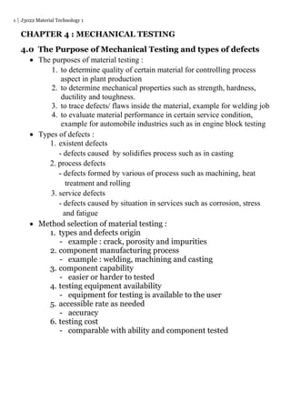
Surface area of indentation with diameter d (mm) indented by
ball indenter D (mm) is given by the following formula :
Brinell Hardness Number (HB) given by :
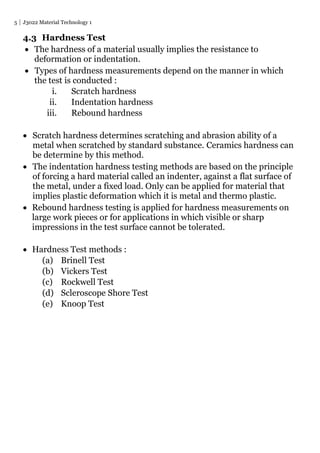
HB = test load
surface area of indentation
= 2 P
D [ D - (D2 – d2) ]
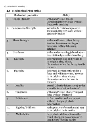
4.3.2 Vickers Hardness Test
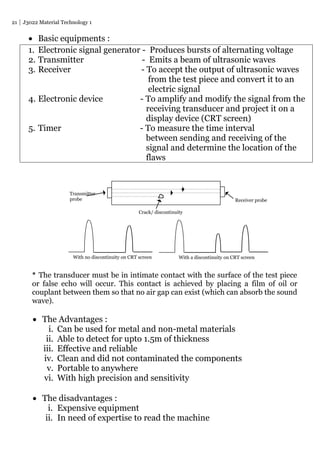
F F
Diamond pyramid (6000 HB) test indentor with an angle of 136,
gives an indentation that appears as a square. Indented with
static loads for 10 to 15 minutes.
Static loads applied for materials used :
Materials Loads (kg)
Steel and cast iron 30
Cuprum alloys 10
Pure cuprum, aluminium alloys 5
Pure aluminium 2.5
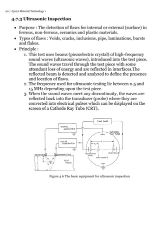
Lead (PB), tin (St) and tin alloys 1
Area = πD [ D - (D2 – d2)] mm2
2](https://image.slidesharecdn.com/chapter4-150322051011-conversion-gate01/85/Material-Technology-7-320.jpg)
![8 J3022 Material Technology 1
The Vickers Hardness Number (HV) given by the formula below :
HV = Test loads
Surface area of the indentation
= F (kg)
d2 / [2 sin / 2] where = 136°
= 2 F sin 68°
d2
d2
= 1.8544 F
d2
F = test load (kg) d1
d = average length of diagonals (mm)
The main advantages of the Vickers hardness testing machine are :
1. Automatically timing
2. Small-sized indentation
3. Accurate method of reading the diagonal of the indentation
4. Constancy of indentation shape produced by the pyramidal
diamond indenting tool
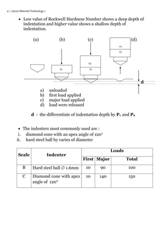
4.3.3 Rockwell Hardness Test
Principle :
Comparing the difference of indenter depth when using 2
difference forces. A minor force is first applied and the scales are
set to read zero, then a major force is applied at the same
indentation. The increased depth of indentation is shown on the
scales of the machine as a direct reading of hardness without the
need for calculation or conversion tables.
The indenter used in this test is either a hardened steel ball or a
carefully ground diamond cone.
d = d1 + d2
2](https://image.slidesharecdn.com/chapter4-150322051011-conversion-gate01/85/Material-Technology-8-320.jpg)

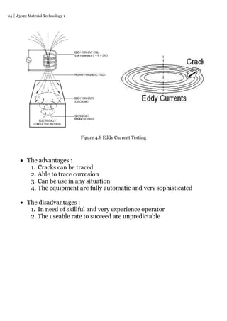

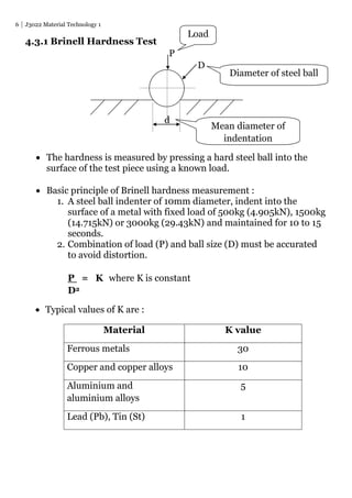
Mechanical testing is used to determine material properties and detect defects. There are destructive and non-destructive tests. Destructive tests like tensile, impact and hardness testing damage samples, while non-destructive tests like dye penetrant, magnetic particle and ultrasonic inspection detect flaws without damage. Selection of test method depends on material, manufacturing process, component capability and cost considerations. Common mechanical properties tested include strength, hardness, ductility and toughness.


