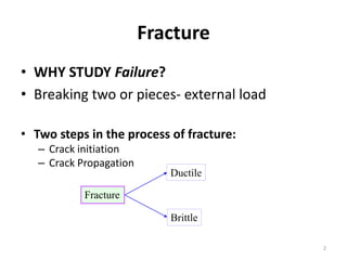
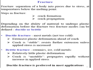
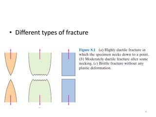
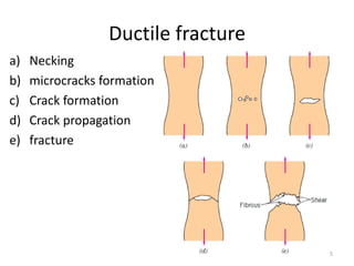
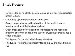
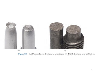
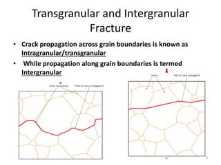
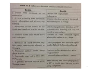
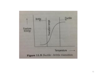
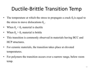
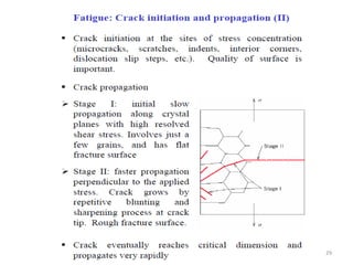
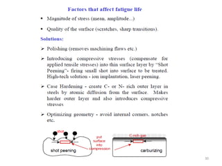
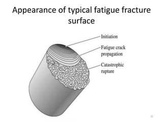
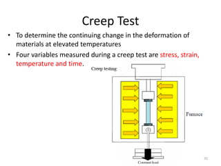
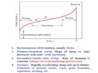
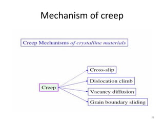
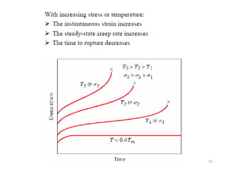
Fracture, Fatigue and Creep
Bessy johny
Asst. Prof.
1
Fracture
• WHY STUDY Failure?
• Breaking two or pieces- external load
• Two steps in the process of fracture:
– Crack initiation
– Crack Propagation
Fracture
Brittle
Ductile
2
3
• Different types of fracture
4
Ductile fracture
a) Necking
b) microcracks formation
c) Crack formation
d) Crack propagation
e) fracture
5
Brittle Fracture
• Exhibits little or no plastic deformation and low energy absorption
before failure.
• Crack propagation spontaneous and rapid
• Occurs perpendicular to the direction of the applied stress,
forming an almost flat fracture surface.
• Crack propagation corresponding to Successive and repeated
breaking of atomic bonds along specific crystallographic planes is
called cleavage
• This type of fracture is called cleavage fracture
• This type of fracture are generally found in BCC and HCP, but not
FCC
6
7
Transgranular and Intergranular
Fracture
• Crack propagation across grain boundaries is known as
Intragranular/transgranular
• While propagation along grain boundaries is termed
Intergranular
8
9
Ductile – Brittle Transition
• Ductile materials fracture abruptly and with little plastic
deformation
• Crack propagation takes precedence over plastic deformation
• Ductile – Brittle transition occurs when
1. Temperature is lowered
2. Rate of straining increased
3. Notch or stress raiser is introduced
10
11
Ductile-Brittle Transition Temp
• The temperature at which the stress to propagate a crack бf is equal to
the stress to move dislocations бy .
• When бy < бf material is ductile
• When бy > бf material is brittle
• This transition is commonly observed in materials having BCC and
HCP structures.
• For ceramic materials, the transition takes place at elevated
temperatures.
• For polymers the transition occurs over a narrow range, below room
temp.
12
Griffith theory of fracture
• Measured fracture strength of most brittle materials are
significantly lower than theoretical strength- what is the
reason?
• Stress concentration
• Brittle materials contains a population of fine cracks which
produce a stress concentration
• Stress amplification is assumed to be at the crack tip
• Magnitude of this amplification depends on the crack
orientation and geometry
13
• It is assumed that the crack is elliptical in shape and is
oriented with major axis perpendicular to the applied stress
14
• Maximum stress at the crack tip
𝜎 𝑚=2𝜎𝑜
𝑐
𝜌
15
• Increase in surface energy is required to generate extra surface
area
• Source of this increased surface energy is the elastic energy
which is released as the crack spreads
• Griffith criterion -A crack will propagate when the decrease
in elastic strain energy is at least equal to the energy required to
create the new crack surface
• The change in surface energy due to the change in crack length
must be just equal to the change in elastic strain energy.
•
𝑑𝑈 𝐸
𝑑𝑐
=
𝑑𝑈 𝑠
𝑑𝑐
16
Protection against fracture
• Introducing compressive stresses
• Polishing surfaces
• Avoiding sharp corners
• Improving purity of the materials
• Grain refinement
• Avoid precipitation of second phase
17
Fracture mechanics
• It is the discipline concerned with the
behavior of materials containing cracks or
small flaws.
• Fracture toughness measures the ability of the
material containing a flaw to withstand an
applied load.
• Stress intensity factor
𝐾 = 𝑓𝜎 𝜋𝑐
Unit is MPa 𝑚
18
Significance
• Used to design and select materials
considering the inevitable presence of flaws
19
Mode of fracture
20
21
22
23
24
25
26
27
28
29
30
Appearance of typical fatigue fracture
surface
31
CREEP
32
• Permanent deformation of materials on the application of
a load can be either plastic deformation or creep.
• The permanent deformation at temperature below
0.4 Tm is called PLASTIC DEFORMATION.
• Amount of deformation occurring after the application of
load is negligible. Rate at which material deformed
determines deformation characteristics
• At temp above 0.4 Tm permanent deformation is a
function of time too. This behaviour is CREEP.
33
• Materials are often placed under steady loads for
longer periods of time
• Without increase in load materials undergoes
deformation
• Creep is predominant at higher temperature, ie.
An elevated temperature effect.
• Creep is a time-dependent and permanent
deformation of materials when subjected to a
constant load at a high temperature over a longer
periods. (> 0.4 Tm).
34
Creep Test
• To determine the continuing change in the deformation of
materials at elevated temperatures
• Four variables measured during a creep test are stress, strain,
temperature and time.
35
Creep curves
• Shows the relationship between creep strain
vs time at a particular temperatures.
36
37
Mechanism of creep
38
Creep resistant materials
• Materials of high melting point like
refractories, superalloys, ceramics etc.
• Alloys with solutes of lower diffusivity
• Coarse grained materials
• Directionally solidified alloys with columnar
grains
• Single grained materials
39
Factors affecting creep
1. Thermal stability and melting point
2. Grain size and shape
3. Precipitation hardening
4. Dispersion hardening
5. Cold working or work hardening
6. Formation of substitutional solid solution
40
Structural changes during creep
1. Deformation by slip
2. Sub-grain formation
3. Grain boundary sliding
41
0000000
42
Superplasticity
• The unusual ability of some metals and alloys to elongate
uniformly thousands of percent at elevated temperatures, much
like hot polymers or glasses.
• Most superplastic alloys are of eutectic or eutectoid
compositions.
43
44
conditions
• The material must possess very fine grain size
• It must be highly strain rate sensitive
• A high loading temperature, greater than 50% of the melting
temperature of the metal
• A low controlled strain rate
• Presence of second phase is also preferred
45
Applications
• Widely made use of in metal forming processes like
thermoforming, blow forming, vacuum forming, deep drawing
etc. for the production of large complex shaped products.
• Deep or complex shapes can be made as one piece, single
operation pressings, rather than multistep conventional
pressings or multi piece assemblies.
• The elevated temperatures required to promote superplasticity
also reduce the flow stress of the material and thereby the
force requirements.
46

Fractue fatigue and creep

  • 1.
    Fracture, Fatigue andCreep Bessy johny Asst. Prof. 1
  • 2.
    Fracture • WHY STUDYFailure? • Breaking two or pieces- external load • Two steps in the process of fracture: – Crack initiation – Crack Propagation Fracture Brittle Ductile 2
  • 3.
  • 4.
    • Different typesof fracture 4
  • 5.
    Ductile fracture a) Necking b)microcracks formation c) Crack formation d) Crack propagation e) fracture 5
  • 6.
    Brittle Fracture • Exhibitslittle or no plastic deformation and low energy absorption before failure. • Crack propagation spontaneous and rapid • Occurs perpendicular to the direction of the applied stress, forming an almost flat fracture surface. • Crack propagation corresponding to Successive and repeated breaking of atomic bonds along specific crystallographic planes is called cleavage • This type of fracture is called cleavage fracture • This type of fracture are generally found in BCC and HCP, but not FCC 6
  • 7.
  • 8.
    Transgranular and Intergranular Fracture •Crack propagation across grain boundaries is known as Intragranular/transgranular • While propagation along grain boundaries is termed Intergranular 8
  • 9.
  • 10.
    Ductile – BrittleTransition • Ductile materials fracture abruptly and with little plastic deformation • Crack propagation takes precedence over plastic deformation • Ductile – Brittle transition occurs when 1. Temperature is lowered 2. Rate of straining increased 3. Notch or stress raiser is introduced 10
  • 11.
  • 12.
    Ductile-Brittle Transition Temp •The temperature at which the stress to propagate a crack бf is equal to the stress to move dislocations бy . • When бy < бf material is ductile • When бy > бf material is brittle • This transition is commonly observed in materials having BCC and HCP structures. • For ceramic materials, the transition takes place at elevated temperatures. • For polymers the transition occurs over a narrow range, below room temp. 12
  • 13.
    Griffith theory offracture • Measured fracture strength of most brittle materials are significantly lower than theoretical strength- what is the reason? • Stress concentration • Brittle materials contains a population of fine cracks which produce a stress concentration • Stress amplification is assumed to be at the crack tip • Magnitude of this amplification depends on the crack orientation and geometry 13
  • 14.
    • It isassumed that the crack is elliptical in shape and is oriented with major axis perpendicular to the applied stress 14
  • 15.
    • Maximum stressat the crack tip 𝜎 𝑚=2𝜎𝑜 𝑐 𝜌 15
  • 16.
    • Increase insurface energy is required to generate extra surface area • Source of this increased surface energy is the elastic energy which is released as the crack spreads • Griffith criterion -A crack will propagate when the decrease in elastic strain energy is at least equal to the energy required to create the new crack surface • The change in surface energy due to the change in crack length must be just equal to the change in elastic strain energy. • 𝑑𝑈 𝐸 𝑑𝑐 = 𝑑𝑈 𝑠 𝑑𝑐 16
  • 17.
    Protection against fracture •Introducing compressive stresses • Polishing surfaces • Avoiding sharp corners • Improving purity of the materials • Grain refinement • Avoid precipitation of second phase 17
  • 18.
    Fracture mechanics • Itis the discipline concerned with the behavior of materials containing cracks or small flaws. • Fracture toughness measures the ability of the material containing a flaw to withstand an applied load. • Stress intensity factor 𝐾 = 𝑓𝜎 𝜋𝑐 Unit is MPa 𝑚 18
  • 19.
    Significance • Used todesign and select materials considering the inevitable presence of flaws 19
  • 20.
  • 21.
  • 22.
  • 23.
  • 24.
  • 25.
  • 26.
  • 27.
  • 28.
  • 29.
  • 30.
  • 31.
    Appearance of typicalfatigue fracture surface 31
  • 32.
  • 33.
    • Permanent deformationof materials on the application of a load can be either plastic deformation or creep. • The permanent deformation at temperature below 0.4 Tm is called PLASTIC DEFORMATION. • Amount of deformation occurring after the application of load is negligible. Rate at which material deformed determines deformation characteristics • At temp above 0.4 Tm permanent deformation is a function of time too. This behaviour is CREEP. 33
  • 34.
    • Materials areoften placed under steady loads for longer periods of time • Without increase in load materials undergoes deformation • Creep is predominant at higher temperature, ie. An elevated temperature effect. • Creep is a time-dependent and permanent deformation of materials when subjected to a constant load at a high temperature over a longer periods. (> 0.4 Tm). 34
  • 35.
    Creep Test • Todetermine the continuing change in the deformation of materials at elevated temperatures • Four variables measured during a creep test are stress, strain, temperature and time. 35
  • 36.
    Creep curves • Showsthe relationship between creep strain vs time at a particular temperatures. 36
  • 37.
  • 38.
  • 39.
    Creep resistant materials •Materials of high melting point like refractories, superalloys, ceramics etc. • Alloys with solutes of lower diffusivity • Coarse grained materials • Directionally solidified alloys with columnar grains • Single grained materials 39
  • 40.
    Factors affecting creep 1.Thermal stability and melting point 2. Grain size and shape 3. Precipitation hardening 4. Dispersion hardening 5. Cold working or work hardening 6. Formation of substitutional solid solution 40
  • 41.
    Structural changes duringcreep 1. Deformation by slip 2. Sub-grain formation 3. Grain boundary sliding 41
  • 42.
  • 43.
    Superplasticity • The unusualability of some metals and alloys to elongate uniformly thousands of percent at elevated temperatures, much like hot polymers or glasses. • Most superplastic alloys are of eutectic or eutectoid compositions. 43
  • 44.
  • 45.
    conditions • The materialmust possess very fine grain size • It must be highly strain rate sensitive • A high loading temperature, greater than 50% of the melting temperature of the metal • A low controlled strain rate • Presence of second phase is also preferred 45
  • 46.
    Applications • Widely madeuse of in metal forming processes like thermoforming, blow forming, vacuum forming, deep drawing etc. for the production of large complex shaped products. • Deep or complex shapes can be made as one piece, single operation pressings, rather than multistep conventional pressings or multi piece assemblies. • The elevated temperatures required to promote superplasticity also reduce the flow stress of the material and thereby the force requirements. 46